Design of Testing Equipment of Ultra Low
Head Hydraulic Turbine Model to Support
Implementation the Laboratory Work of
Machine Performance at Mechanical
Engineering Department
Jorfri Boike Sinaga
a*,
Ahmad Suudi
bM. Aang Khonaifi
c, Milia
Rahman
d, and Sugiman
Mechanical Engineering Department, Faculty of Engineering, University of Lampung, Province of Lampung, Indonesia
a
[email protected],[email protected],[email protected],d [email protected]
Abstract
Mechanical Engineering Department, University of Lampung has been established since 1998 and in the implementation of learning process at this departmen supported by ten laboratories, that is: Laboratory of CNC, Laboratory of Drafting, Laboratory of Materials, Laboratory of Manufactured, Laboratory of Computer, Laboratory of Industry Metrology, Laboratory of Structural Mechanics, Laboratory of Thermodynamics, Laboratory of Fluid Mechanics, and Laboratory of Combustion Engine. These laboratories are used as research means for the lecturers and the students and also for the implementation of the subject of available laboratory work in the curriculum of Mechanical Engineering Department, University of Lampung, One of the subjects of laboratory work is machine performance, where this laboratory work is carried out in three laboratories, that is Laboratory of Thermodynamics, Laboratory of Fluid mechanics, and Laboratory of Combustion Engine. The testing equipments are available until now, namely, vapour compression refrigeration system, Pelton turbine, and combustion engine, and these testing equipments need for the addition to support this laboratory work. However the funding from university is very limited. Therefore addition testing equipment must be made. In this paper design of a testing equipment of ultra low head hydraulic turbine model is presented to be used for laboratory work of machine performance in Mechanical Engineering Department, University of Lampung.
Keywords:
Hydraulic Turbine, Helical Turbine, Ultra Low Head, Laboratory Work, Machine Performance1. Introduction
The Department of Mechanical Engineering is one of the departments located in the
Faculty of Engineering, University of Lampung, and this department was established in
human resources, laboratories, physical buildings and learning process and office
facilities. The goal of establishing of this Mechanical Engineering Department is:
1. To develop graduates who have a reasonable, logical and rational mindset with the
basic knowledge of Mechanical Engineering to be able to analyze and synthesize
machine characteristics.
2. To develop graduates who have the ability to create new solutions, adopt old
solutions, and use the knowledge gained in the science of energy conversion, design
and construction, materials and manufacturing.
3. To develop graduates who can model and predict the behavior of engineering
equipment through the application of scientific and technological principles.
One of the missions to achieve this goal is to carry out an effective and efficient learning
process by improving facilities and infrastructure to support the learning process
including laboratory equipment.
The learning process carry out at the Mechanical Engineering Department of Faculty
of Engineering, University of Lampung is currently supported by 10 laboratories, namely:
Laboratory of CNC, Laboratory of Drafting, Laboratory of Materials, Laboratory of
Manufactured, Laboratory of Computer, Laboratory of Industry Metrology, Laboratory of
Structural Mechanics, Laboratory of Thermodynamics, Laboratory of Fluid Mechanics,
and Laboratory of Combustion Engine. These laboratories are used as research
facilities for lecturers and students and also for the implementation of laboratory work
courses in the curriculum of the Department of Mechanical Engineering, Faculty of
Engineering, University of Lampung. One of the laboratory work courses is the
laboratory work of machine performance. This laboratory work is carried out so that
students are able to determine and measure the performance parameters of energy
conversion machines by applying theories that have been obtained in the courses of
Fluid Mechanics, Thermodynamics, and Energy Conversion Machines. However, the
testing equipment to carry out the laboratory work of machine performance is still
lacking, where the testing equipments are available until now, combustion engine,
Pelton turbine and Air Conditioning (AC). This is caused by the limited funds provided by
the university to supply the testing equipment in the laboratory. So it is necessary to
develop additional testing equipment to support the implementation of this laboratory
work. In this paper is given the design and development of testing equipment of ultra low
head hydraulic turbine model to support implementation the laboratory work of machine
performance in Mechanical Engineering Department, University of Lampung.
1.1.Hydraulic Turbine for Very Low Flow Head
For decades scientists have tried to use conventional turbines for low flow heads.
Highly efficient water turbines for high flow heads are very expensive when applied to
hydropower stations with low or very low heads. The main types of water turbines
currently used to harness hydropower are: Kaplan, Francis, Pelton, and cross flow
turbines. The Kaplan turbine is one of the water turbines which technically can be used
for a two meter head height or a lower water head but the turbine operating unit cost
increases up to about four times when the water heads fall from 5 to 2 meters.
In 1931 Darrieus patented reaction turbine to use low or very low head flow energy
(free flow). This turbine has a drum-like shape with a number of straight or curved
blades of airfoil and a shaft that is perpendicular to the fluid flow. This turbine allows
high torque for slow current flow, and provides a large fluid flow through the turbine
without enlarging the diameter. However, the Darrieus turbine has not been acceptable
for large applications, mainly due to fluctuations during rotation and relatively low
efficiency. Fatigue failure of the blade generally occurs in this turbine due to the nature
of the vibration that occurs. This turbine also has an initial operating problem at low
rotational speed due to a straight blade that changes the angle of attack.
Gorlov [1] explained the helical turbine has the same advantages as the Darrieus
turbine, for example: able to pass a large mass of water for slow flow, kinetic energy
capturing, and the low cost turbine for using a very simple rotor blade. The helical
arrangement of the rotor blades also makes the performance of the helical turbine better
as compare with the Darrieus turbine. It results the characteristics: uniform turbine
rotation at high speed in relatively slow fluid flow, unidirectional rotation in reversible
fluid currents, high efficiency, no fluctuating torque, no cavitation in water for high
rotating speed, self-starting better in slow flow of waters.
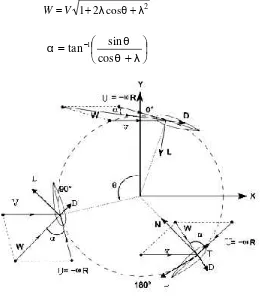
An approximation of the vertical axis turbine is used to calculate the power was
generated by this helical turbine blade, as can be seen in Figure 1. The resultant
velocity vector (W) is the sum of the velocity vector of fluid (V) andthe velocity vector of
the advancing blade(U).
R
V
W
ω
(1)where R is the radius of turbine (m), and ω is the angular velocity of turbine (rad/ s).
From the Figure 1, the resulting offluidvelocity varies, the maximumis found forθ = 0O
and the minimum is found for θ = 180O, where θ is the azimuthal or orbital blade
blade’s chord. From geometrical considerations, the resultant of flow velocity and the
angle of attack are calculated as follows:
2
Figure 1.Forces and velocities acting in avertical axis wind turbinefor various azimuthal
positions.
where λ is tip speed ratio, and can be calculated by using the following equation
U
which these forces can be calculated using the following equation:
A
The force perpendicular to the arm (radius) of turbine, the torque by projecting lift and
drag forces can be calculated using the following equation:
R F
F
T ( l.sinα d.cosα) (7)
where T is the torque (N.m), F is the force perpendicular to the arm (N), and R is the
radius (m). From Equation 7, the shaft power Pb (W) can be calculated using the
equation:
ω
T
P
b
(8)
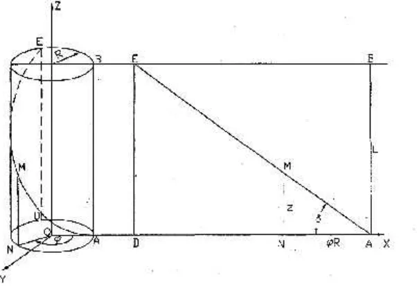
1.2.Mathematical Model for Design of Helical Turbine
In Figure 2 [4], It can be seen helical blades formed AME lines on the surface of a
cylinder having height L and radius R. The helical blade equation is defined by:
ϕ cos R
X Y Rsinϕ Z Rϕcosδ (9)
where x, y and z are the coordinates of the point M of the helix, and δ is the angle of
inclination ofthe blade to the XOY plane.
Figure 2. Projection of the blade line on vertical plane.
As an approximation that the cross section of the blade has the shape of an infinitely
thin rectangle with its length equal to the chord c of the blade’s airfoil. This does not
change the proportion between lifts and drags after resolution of the reaction force F
2 o
A
V
k
=
F
(10)where: ko is a constant, ρ iswater density, A is projection of the frontal area of the blade
on the plane perpendicular to the water flow, and V is velocity of water.
The total starting torque developed by the turbine blades in the water flow can be
expressed by the equation
In dimensionless can be written
ratio of the turbine height to its radius L/R.
Figure 3. The torque relation T1as a function ofangle of blade inclination δandthe ratio
2. Materials and Methods
2.1Determining the Turbine Parameters
The model of designed turbine to be used in the testing equipmentis shown in Figure 4.
The parameters of turbine to be determined: height of turbine L, diameter of turbine R,
shape of blade, number of blades n, andangle of blade inclination δ.
Figure 4. Scheme of helical turbine model
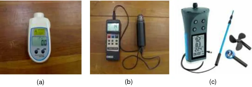
Determining dimensions of the testing equipment system and the parameters of the
helical turbine to be used should consider the Fluid Mechanics Laboratory conditions
and the available measurement instruments. The measurement instruments used to
execute this laboratory experiment are torque meter to measure the torque produced by
shaft turbine (N.cm), with the maximum torque meter of 147 N.cm, tacho meter to
measure the speed of turbine rotation (rpm) and propeller flow meter to measure the
velocity of flow (m/s).
(a) (b) (c)
Figure 5. Photograph ofmeasurement instruments: a. tacho meter, b. torque meter, and
c.propeller flow meter
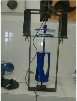
2.2. Construction of Testing Equipment
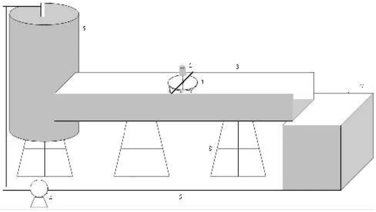
Scheme of the testing equipment design can be seen in Figure 6. This device
transforms kinetic energy derived from flow of low head, to turn a turbine to produces
mechanical energy of rotation and whose primary function is to drive a electric
Figure 6. Schematic of testing equipment system Caption:
1. Helical turbine 2.Torque meter
3. Channel 4. Pump
5. Pipe 6. Tank
7. Reservoir 8. Testing equipment supporting
The efficiency ηtof helical turbine model can be calculated using the equation:
3 t sys
.V ρ.A 0,5 η
Pt (13)
Where Pt is power generated by turbine shaft (W), it can be calculated using the
Equation 7,ρ is water density (kg/m3), V is velocity of water flow (m/s), and At is cross
sectional area of helical turbine(m2).
3. Results and discussion.
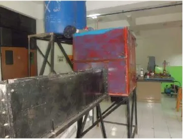
3.1. Model of Testing EquipmentSystem
According to the conditions of space of the Fluid Mechanics Laboratory, dimensions of
thank andcross-sectionalarea of channelwere determined 1 m x 1 m x 1 m and 20 cm
x 30 cm respectively. The available head of flow is 1 m to run the experiment. The
velocity of flow in channel was measured by propeller flow meter and it can be varied to
Figure 5. Systemof testing equipment
3.2.Turbine Design
Generally helical turbine uses blade’s airfoil, due to its high efficiency and produces a large pressure difference between two sides of blade to rotate with a considerable force moment in which the force moment is generated by lift and drag force. The lift and drag forces that occur in the airfoil sections are influenced by the shape of blade and the angle of attack.The symmetry airfoils ofNACA 0030 [3] was used for the turbine blades.
Figure 8. Parameters of NACA airfoil
According to conditions of the channel, helical turbine to be used has 10 cm in diameter
and 20 cm in height.Usingequation 12, for the ratio of height to radius of turbine L/R of
The performance of helical turbine operation is also influenced byrelative solidity. Itcan
be calculated using the equation[4]:
R
where σ is parameter ofrelative solidity,S is solidity of the helical turbine, L isheight of
theturbine, and R is radius of the turbine. solidity ofthehelical turbine can be calculated
using the equation:
respect to the axis of rotation.
Figure 9 [5] is shown the effect of tip speed ratio λ to coefficient of performance Cp
(efficiency) for each relative solidity σ of hydrokinetic turbine (HKT) Darrieus with straight
blade.
Figure 9.Predicted and measured performance of Darrieus HKTs of varying solidity
The tip speed ratio of turbine operation was determined λ = 3 [4], this is to prevent
cavitation during turbine operation. From Figure 10, for tip speed ratio λ = 3, it was
obtained the relative solidity σ ≈ 0.4 as proposed by Shiono et. all.[6|. Based on previous
study [7], operating the helical turbine with tree blades was given the maximum
efficiency, however to see the influence of the number of blades on performance
characteristic of turbine, turbine with two blades also developed. Using Equation of 14
Figure 10. Model of helical turbine with tree blades
3.4. TestingResults and Discussion
Figure11. Testing of the developed testing equipment
0
b. Influence of volume flow rate on the shaft power
0
c. Influence of volume flow rate on the efficiency
0.1
a. Influence of volume flow rate on the torque
0 0.27
0 0.27 0.450.380.240
c. Influence of volume flow rate on the efficiency
Figure13. The testing results of helical turbinemodel with using 3 number of blades
The developed testing equipment of ultra low head hydraulic turbine model can perform the performance characteristics of helical turbine. Using this testing equipment will help the students to understand how the working principle of helical turbine to convert kinetic energy of water flow into mechanical energy. The testing results also show how the number of blades and velocity of flow influence the performance characteristics of helical turbine. Therefore this testing equipment of ultra low head hydraulic turbine model can be used to support implementation the laboratory work of machine performance in Mechanical Engineering Department. This testing equipment will also help the students who interested in studying the performance of this turbine when it is applied in the system of hydro electric power generation to utilize kinetic energy derived from flow of low head or stream of water.
4. Conclusions
Based on the results that have been obtained and described earlier, it can be taken
some conclusions:
1. In this research is given design method of the testing equipment of ultra low head
hydraulic turbine model to support implementation the laboratory work of machine
2. The developed testing equipment of ultra low head hydraulic turbine model can
perform the performance characteristics of helical turbine to utilize the stream flow
energy which has very low head or only kinetic energy.
3. The test results show the number of blades and velocity of flow influence the
performance characteristics of helical turbine whereusing 3 number of blades gives
the maximum of turbine efficiency of 28.03 %.
4.The course of this laboratory work will provide an opportunity for students to develop
their competency in design and execution of laboratory experiments, analysis and
interpretation of data use information from the engineering literature including basic
concepts from the courses have introduced by the lecturer especially fluid
mechanics, energy conversation and fluid machinery subject.
.
Acknowledgment
This research work was supported by Penelitian Produk Terapan Grant 2017. The
authors would like to acknowledge the financial support from Ministry of Research,
Technology, and Higher Education of the Republic of Indonesia.
References
[1]Alexander G 2008 Development of The Helical Reaction Turbine. Final Technical
Report (DE-GO1-96EE15669)
[2] Jorfri B S, Ahmad S, Aang K, Milia R, and Sugiman, 2017 Perancangan Alat
Pengujian Model Turbin Air Ultra Low Head untuk Sistem Pembangkit Listrik
Tenaga Mikro Hidro (PLTMH), Prosiding Seminar Nasional Energi dan Industri
Manufaktur 2017, Universitas Lampung, Bandar Lampung
[3] Andareas W S, Jorfri B S, and Agus S, 2014 Kajian Eksperimental Pengaruh Bentuk
Sudu terhadap Unjuk Kerja Turbin Helik untuk Model Sistem Pembangkit Listrik
Tenaga Mikro Hidro (PLTMH), Jurnal FEMA, Jurusan Teknik Mesin Universitas
Lampung, 2 pp 72–78
[4] Alexander G 2010 Helical Turbine and Fish Safety Available:
www.mainetidalpower.com/files/gorlovrevised.pdf. Accesed on April 22, 2015
[5] B K Kirke, 2011Renewable Energy. 36: 3013-3022
[6] Shiono, M., Kdsuyuki S,and Sezji, K. 2002. Output Characteristics of Darrieus Water
Twelfth (2002) International Offshore and Polar Engineering Conference Kitakyushu,
Japan, May 26 2002
[7] Dwi S 2016 Kajian Eksperimental Pengaruh Jumlah Sudu terhadap Unjuk Kerja
Turbin Helik untuk Sistem Pembangkit Listrik Tenaga Mikro Hidro (PLTMH). Tugas
![Figure 3 [2] shows the torque T, as a function of angle of blade inclination δ and the](https://thumb-ap.123doks.com/thumbv2/123dok/3993974.1937394/6.595.172.474.437.658/figure-shows-torque-t-function-angle-blade-inclination.webp)
![Figure 9 [5] is shown the effect of tip speed ratio λ to coefficient of performance Cp(efficiency) for each relative solidity σ of hydrokinetic turbine (HKT) Darrieus with straight](https://thumb-ap.123doks.com/thumbv2/123dok/3993974.1937394/10.595.229.469.407.586/coefficient-performance-efficiency-relative-solidity-hydrokinetic-darrieus-straight.webp)