Firmware Manual
Firmware Manual
Table of contents
Table of contents
Introduction to the manual
Chapter overview . . . 13
Compatibility . . . 13
Safety instructions . . . 13
Reader . . . 13
Contents . . . 13
Product and service inquiries . . . 14
Product training . . . 14
Providing feedback on ABB Drives manuals . . . 14
Start-up and control through the I/O
Chapter overview . . . 15
How to start-up the drive . . . 15
How to perform the guided start-up (covers all essential settings) . . . 15
How to perform the limited start-up (covers only the basic settings) . . . 17
How to control the drive through the I/O interface . . . 21
How to perform the ID Run . . . 22
ID Run Procedure . . . 22
Control panel
Chapter overview . . . 25
Overview of the panel . . . 25
Panel operation mode keys and displays . . . 26
Status row . . . 26
Drive control with the panel . . . 27
How to start, stop and change direction . . . 27
How to set speed reference . . . 28
Actual signal display mode . . . 29
How to select actual signals to the display . . . 29
How to display the full name of the actual signals . . . 30
How to view and reset the fault history . . . 30
How to display and reset an active fault . . . 31
About the fault history . . . 31
Parameter mode . . . 32
How to select a parameter and change the value . . . 32
How to adjust a source selection (pointer) parameter . . . 33
Function mode . . . 34
How to enter an assistant, browse and exit . . . 35
How to download data from the panel to a drive . . . 37
How to set the contrast of the display . . . 38
Drive selection mode . . . 39
How to select a drive and change its panel link ID number . . . 39
Reading and entering packed boolean values on the display . . . 40
Program features
Chapter overview . . . 41
Start-up Assistant . . . 41
Introduction . . . 41
The default order of the tasks . . . 41
List of tasks and the relevant drive parameters . . . 42
Contents of the assistant displays . . . 43
Local control vs. external control . . . 43
Local control . . . 44
External control . . . 44
Settings . . . 44
Diagnostics . . . 44
Block diagram: start, stop, direction source for EXT1 . . . 45
Block diagram: reference source for EXT1 . . . 45
Reference types and processing . . . 46
Settings . . . 46
Diagnostics . . . 46
Reference trimming . . . 47
Settings . . . 47
Example . . . 48
Programmable analogue inputs . . . 49
Update cycles in the Standard Control Program . . . 49
Settings . . . 49
Diagnostics . . . 49
Programmable analogue outputs . . . 50
Update cycles in the Standard Control Program . . . 50
Settings . . . 50
Diagnostics . . . 50
Programmable digital inputs . . . 51
Update cycles in the Standard Control Program . . . 51
Settings . . . 51
Diagnostics . . . 51
Programmable relay outputs . . . 52
Update cycles in the Standard Control Program . . . 52
Settings . . . 52
Diagnostics . . . 52
Actual signals . . . 53
Settings . . . 53
Diagnostics . . . 53
Motor identification . . . 53
Settings . . . 54
Safe torque off (STO) . . . 55
Diagnostics . . . 55
Prevention of unexpected start-up (POUS) . . . 55
Safely-limited speed (SLS) (AS7R firmware version only) . . . 56
Settings . . . 56
Diagnostics and control . . . 56
DC Magnetising . . . 57
Settings . . . 57
DC Hold . . . 57
Settings . . . 57
Flux Braking . . . 57
Settings . . . 58
Flux Optimisation . . . 58
Settings . . . 58
Acceleration and deceleration ramps . . . 59
Settings . . . 59
Critical speeds . . . 59
Settings . . . 59
Constant speeds . . . 59
Settings . . . 59
Speed controller tuning . . . 60
Settings . . . 60
Diagnostics . . . 60
Speed control performance figures . . . 61
Torque control performance figures . . . 61
Scalar control . . . 62
Settings . . . 62
IR compensation for a scalar controlled drive . . . 62
Settings . . . 62
Hexagonal motor flux . . . 63
Settings . . . 63
Programmable protection functions . . . 63
AI<Min . . . 63
Settings . . . 63
Panel Loss . . . 63
Settings . . . 63
External Fault . . . 63
Settings . . . 63
Motor Thermal Protection . . . 64
Motor temperature thermal model . . . 64
Use of the motor thermistor . . . 64
Settings . . . 64
Stall Protection . . . 65
Settings . . . 65
Underload Protection . . . 65
Settings . . . 65
Motor Phase Loss . . . 65
Settings . . . 65
Settings . . . 66
Communication Fault . . . 66
Settings . . . 66
Supervision of optional IO . . . 66
Settings . . . 66
Preprogrammed faults . . . 66
Overcurrent . . . 66
DC overvoltage . . . 66
DC undervoltage . . . 67
Drive temperature . . . 67
Enhanced drive temperature monitoring for ACS800, frame sizes R7 and R8 . . . 67
Settings . . . 68
Diagnostics . . . 68
Short circuit . . . 68
Input phase loss . . . 68
Control board temperature . . . 68
Overfrequency . . . 68
Internal fault . . . 68
Operation limits . . . 68
Settings . . . 68
Power limit . . . 69
Automatic resets . . . 69
Settings . . . 69
Supervisions . . . 69
Settings . . . 69
Diagnostics . . . 69
Parameter lock . . . 69
Settings . . . 69
Process PID control . . . 70
Block diagrams . . . 70
Settings . . . 71
Diagnostics . . . 71
Sleep function for the process PID control . . . 71
Example . . . 72
Settings . . . 72
Diagnostics . . . 72
Motor temperature measurement through the standard I/O . . . 73
Settings . . . 74
Diagnostics . . . 74
Motor temperature measurement through an analogue I/O extension . . . 75
Settings . . . 76
Diagnostics . . . 76
Adaptive Programming using the function blocks . . . 76
DriveAP . . . 76
Control of a mechanical brake . . . 77
Example . . . 77
Operation time scheme . . . 78
Master/Follower use of several drives . . . 80
Settings and diagnostics . . . 80
Jogging . . . 81
Settings . . . 82
Reduced Run function . . . 82
Settings . . . 82
Diagnostics . . . 82
User load curve . . . 83
Overload . . . 83
Settings . . . 84
Diagnostics . . . 84
Application macros
Chapter overview . . . 85
Overview of macros . . . 85
Note on external power supply . . . 86
Parameter settings . . . 86
Factory macro . . . 87
Default control connections . . . 88
Hand/Auto macro . . . 89
Default control connections . . . 90
PID Control macro . . . 91
Connection example, 24 VDC / 4…20 mA two-wire sensor . . . 91
Default control connections . . . 92
Torque Control macro . . . 93
Default control connections . . . 94
Sequential Control macro . . . 95
Operation diagram . . . 95
Default control connections . . . 96
User macros . . . 97
Actual signals and parameters
Chapter overview . . . 99
Terms and abbreviations . . . 99
01 ACTUAL SIGNALS . . . 100
02 ACTUAL SIGNALS . . . 102
03 ACTUAL SIGNALS . . . 102
04 ACTUAL SIGNALS . . . 103
09 ACTUAL SIGNALS . . . 103
10 START/STOP/DIR . . . 105
11 REFERENCE SELECT . . . 107
12 CONSTANT SPEEDS . . . 113
13 ANALOGUE INPUTS . . . 116
14 RELAY OUTPUTS . . . 119
15 ANALOGUE OUTPUTS . . . 125
16 SYST CTRL INPUTS . . . 127
20 LIMITS . . . 130
22 ACCEL/DECEL . . . 135
23 SPEED CTRL . . . 138
24 TORQUE CTRL . . . 140
25 CRITICAL SPEEDS . . . 140
26 MOTOR CONTROL . . . 141
27 BRAKE CHOPPER . . . 143
30 FAULT FUNCTIONS . . . 144
31 AUTOMATIC RESET . . . 150
32 SUPERVISION . . . 151
33 INFORMATION . . . 152
34 PROCESS VARIABLE . . . 153
35 MOT TEMP MEAS . . . 155
40 PID CONTROL . . . 157
42 BRAKE CONTROL . . . 162
45 ENERGY OPT . . . 164
50 ENCODER MODULE . . . 165
51 COMM MODULE DATA . . . 166
52 STANDARD MODBUS . . . 166
60 MASTER/FOLLOWER . . . 166
70 DDCS CONTROL . . . 168
72 USER LOAD CURVE . . . 169
83 ADAPT PROG CTRL . . . 171
84 ADAPTIVE PROGRAM . . . 172
85 USER CONSTANTS . . . 173
90 D SET REC ADDR . . . 174
92 D SET TR ADDR . . . 175
95 HARDWARE SPECIF . . . 175
96 EXTERNAL AO . . . 178
98 OPTION MODULES . . . 181
99 START-UP DATA . . . 186
Fieldbus control
Chapter overview . . . 191
System overview . . . 191
Redundant fieldbus control . . . 192
Setting up communication through a fieldbus adapter module . . . 193
Setting up communication through the Standard Modbus Link . . . 195
Modbus addressing . . . 196
Setting up communication through Advant controller . . . 197
Drive control parameters . . . 199
The fieldbus control interface . . . 202
The Control Word and the Status Word . . . 203
References . . . 203
Fieldbus reference selection and correction . . . 203
Reference handling . . . 204
Block Diagram: Actual value selection for fieldbus when a type Nxxx fieldbus adapter is used 209
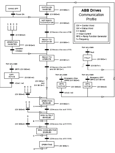
Communication profiles . . . 210
ABB Drives communication profile . . . 210
03.01 MAIN CONTROL WORD . . . 211
03.02 MAIN STATUS WORD . . . 212
Fieldbus reference scaling . . . 214
Generic Drive communication profile . . . 215
Drive commands supported by the Generic Drive communication profile . . . 216
Fieldbus reference scaling . . . 217
CSA 2.8/3.0 communication profile . . . 218
CONTROL WORD for the CSA 2.8/3.0 communication profile . . . 218
STATUS WORD for the CSA 2.8/3.0 communication profile . . . 218
Diverse status, fault, alarm and limit words . . . 219
03.03 AUXILIARY STATUS WORD . . . 219
03.04 LIMIT WORD 1 . . . 220
03.05 FAULT WORD 1 . . . 220
03.06 FAULT WORD 2 . . . 221
03.07 SYSTEM FAULT WORD . . . 222
03.08 ALARM WORD 1 . . . 222
03.09 ALARM WORD 2 . . . 223
03.13 AUXILIARY STATUS WORD 3 . . . 223
03.14 AUXILIARY STATUS WORD 4 . . . 224
03.15 FAULT WORD 4 . . . 224
03.16 ALARM WORD 4 . . . 225
03.17 FAULT WORD 5 . . . 225
03.18 ALARM WORD 5 . . . 226
03.19 INT INIT FAULT . . . 226
03.30 LIMIT WORD INV . . . 227
03.31 ALARM WORD 6 . . . 227
03.32 EXT IO STATUS . . . 228
03.33 FAULT WORD 6 . . . 228
04.01 FAULTED INT INFO . . . 229
04.02 INT SC INFO . . . 230
Fault tracing
Chapter overview . . . 231
Safety . . . 231
Warning and fault indications . . . 231
How to reset . . . 231
Fault history . . . 231
Warning messages generated by the drive . . . 232
Warning messages generated by the control panel . . . 239
Fault messages generated by the drive . . . 240
Analogue Extension Module
Chapter overview . . . 249
Speed control through the analogue extension module . . . 249
Settings of the analogue extension module and the drive . . . 249
Parameter settings: bipolar input in basic speed control . . . 250
Parameter settings: bipolar input in joystick mode . . . 251
Additional data: actual signals and parameters
Chapter overview . . . 253
Terms and abbreviations . . . 253
Fieldbus addresses . . . 253
Rxxx adapter modules (such as RPBA-01, RDNA-01, etc.) . . . 253
Nxxx adapter modules (such as NPBA-12, NDNA-02, etc.) . . . 253
NPBA-12 Profibus Adapter . . . 253
NIBA-01 InterBus-S Adapter . . . 254
NMBP-01 ModbusPlus® Adapter and NMBA-01 Modbus Adapter . . . 254
Actual signals . . . 255
Parameters . . . 258
Control block diagrams
Chapter overview . . . 267
Reference control chain, sheet 1: FACTORY, HAND/AUTO, SEQ CTRL and T CTRL macros
(continued on the next page …) . . . 268
Reference control chain sheet 1: PID CTRL macro (continued on the next page …) . . . 270
Reference control chain sheet 2: All macros (continued on the next page …) . . . 272
Handling of Start, Stop, Run Enable and Start Interlock . . . 274
Handling of Reset and On/Off . . . 275
Introduction to the manual
Chapter overview
The chapter includes a description of the contents of the manual. In addition it
contains information about the compatibility, safety and intended audience.
Compatibility
The manual is compatible with Standard Control Program versions ASXR7360 and
AS7R7363. See parameter
33.01
SOFTWARE VERSION.
Safety instructions
Follow all safety instructions delivered with the drive.
• Read the
complete safety instructions
before you install, commission, or use
the drive. The complete safety instructions are given at the beginning of the
Hardware Manual.
• Read the
software function specific warnings and notes
before changing the
default settings of the function. For each function, the warnings and notes are
given in this manual in the section describing the related user-adjustable
parameters.
Reader
The reader of the manual is expected to know the standard electrical wiring
practices, electronic components, and electrical schematic symbols.
Contents
The manual consists of the following chapters:
•
Start-up and control through the I/O instructs in setting up the application
program, and how to start, stop and regulate the speed of the drive.
•
Control panel gives instructions for using the panel.
•
Program features contains the feature descriptions and the reference lists of the
user settings and diagnostic signals.
•
Application macros contains a short description of each macro together with a
connection diagram.
•
Actual signals and parameters describes the actual signals and parameters of the
drive.
•
Fault tracing lists the warning and fault messages with the possible causes and
remedies.
•
Analogue Extension Module, describes the communication between the drive and
the analogue I/O extension (optional).
•
Additional data: actual signals and parameters contains more information on the
actual signals and parameters.
•
Control block diagrams contains block diagrams concerning reference control
chains and handling of Start, Stop, Run Enable and Start Interlock.
Product and service inquiries
Address any inquiries about the product to your local ABB representative, quoting
the type code and serial number of the unit in question. A listing of ABB sales,
support and service contacts can be found by navigating to
www.abb.com/drives
and
selecting
Sales, Support and Service network
.
Product training
For information on ABB product training, navigate to
www.abb.com/drives
and select
Training courses
.
Providing feedback on ABB Drives manuals
Start-up and control through the I/O
Chapter overview
The chapter instructs how to:
• do the start-up
• start, stop, change the direction of rotation, and adjust the speed of the motor
through the I/O interface
• perform an Identification Run for the drive.
How to start-up the drive
There are two start-up methods between which the user can select: Run the Start-up
Assistant, or perform a limited start-up. The Assistant guides the user through all
essential settings to be done. In the limited start-up, the drive gives no guidance:
The user goes through the very basic settings by following the instructions given in
the manual.
•
If you want to run the Assistant
, follow the instructions given in section How to
perform the guided start-up (covers all essential settings) on page 15.
•
If you want to perform the limited start-up
, follow the instructions given in
section How to perform the limited start-up (covers only the basic settings) on
page 17.
How to perform the guided start-up (covers all essential settings)
Before you start, ensure you have the motor nameplate data on hand.
SAFETY
The start-up may only be carried out by a qualified electrician.
The safety instructions must be followed during the start-up procedure. See the
appropriate hardware manual for safety instructions.
Check the installation. See the installation checklist in the appropriate hardware/installation
manual.
Check that the starting of the motor does not cause any danger.
De-couple the driven machine
if:
- there is a risk of damage in case of incorrect direction of rotation, or
POWER-UP
Apply the main power. The control panel first shows the panel
identification data …
CDP312 PANEL Vx.xx ...
… then the Identification Display of the drive …
ACS800ID NUMBER 1
… then the Actual Signal Display …
1 -> 0.0 rpm OFREQ 0.00 Hz CURRENT 0.00 A POWER 0.00 %
…after which the display suggests starting the Language Selection.
(If no key is pressed for a few seconds, the display starts to alternate between the Actual Signal Display and the suggestion on selecting the language.)
The drive is now ready for the start-up.
1 -> 0.0 rpm O *** INFORMATION *** Press FUNC to start Language Selection
SELECTING THE LANGUAGE
Press the FUNC key.
Language Selection 1/1LANGUAGE ? [ENGLISH]
ENTER:OK ACT:EXIT
Scroll to the desired language by the arrow keys
( or )and
press ENTER to accept.
(The drive loads the selected language into use, shifts back to the Actual Signal Display and starts to alternate between the Actual Signal Display and the suggestion on starting the guided motor set-up.)
1 -> 0.0 rpm O *** INFORMATION *** Press FUNC to start guided Motor Setup
STARTING THE GUIDED MOTOR SET-UP
Press FUNC to start the guided motor set-up.
(The display shows which general command keys to use when stepping through the assistant.)
Motor Setup 1/10 ENTER: Ok/Continue ACT: Exit
FUNC: More Info
Press ENTER to step forward.
Follow the instructions given on the display.
Motor Setup 2/10 MOTOR NAMEPLATE DATA AVAILABLE?
How to perform the limited start-up (covers only the basic settings)
Before you start, ensure you have the motor nameplate data at your hand.
SAFETY
The start-up may only be carried out by a qualified electrician.
The safety instructions must be followed during the start-up procedure. See the
appropriate hardware manual for safety instructions.
Check the installation. See the installation checklist in the appropriate hardware/installation
manual.
Check that the starting of the motor does not cause any danger.
De-couple the driven machine
if:
- there is a risk of damage in case of incorrect direction of rotation, or
- a Standard ID Run needs to be performed during the drive start-up. (ID Run is essential
only in applications which require the ultimate in motor control accuracy.)
POWER-UP
Apply the main power. The control panel first shows the panel
identification data …
CDP312 PANEL Vx.xx ...
… then the Identification Display of the drive …
ACS800ID NUMBER 1
… then the Actual Signal Display …
1 -> 0.0 rpm OFREQ 0.00 Hz CURRENT 0.00 A POWER 0.00 %
…after which the display suggests starting the Language Selection.
(If no key is pressed for a few seconds, the display starts to alternate between the Actual Signal Display and the suggestion on starting the Language Selection.)
1 -> 0.0 rpm O *** INFORMATION *** Press FUNC to start Language Selection
Press ACT to remove the suggestion on starting the language
selection.
The drive is now ready for the limited start-up.
1 -> 0.0 rpm O FREQ 0.00 Hz CURRENT 0.00 A POWER 0.00 %
MANUAL START-UP DATA ENTERING (parameter group 99)
Select the language. The general parameter setting procedure is
described below.
The general parameter setting procedure:
- Press PAR to select the Parameter Mode of the panel.
- Press the double-arrow keys ( or ) to scroll the parameter groups. - Press the arrow keys ( or ) to scroll parameters within a group. - Activate the setting of a new value by ENTER.
- Change the value by the arrow keys ( or ), fast change by the double-arrow keys ( or ).
- Press ENTER to accept the new value (brackets disappear).
Select the Application Macro. The general parameter setting
procedure is given above.
The default value FACTORY is suitable in most cases.
1 -> 0.0 rpm O 99 START-UP DATA 02 APPLICATION MACRO [ ]
Select the motor control mode.
The general parameter setting
procedure is given above.
DTC is suitable in most cases. The SCALAR control mode is recommended - for multimotor drives when the number of the motors connected to the drive is variable
- when the nominal current of the motor is less than 1/6 of the nominal current of the inverter
- when the inverter is used for test purposes with no motor connected.
1 -> 0.0 rpm O 99 START-UP DATA 04 MOTOR CTRL MODE [DTC]
Enter the motor data from the motor nameplate:
Note: Set the motor data to exactly the same value as on the motor nameplate. For example, if the motor nominal speed is 1440 rpm on the nameplate, setting the value of parameter 99.08 MOTOR NOM SPEED to 1500 rpm results in the wrong operation of the drive.- motor nominal voltage
Allowed range: 1/2 · UN
…
2 · UNof ACS800. (UN refers to the highest voltage ineach of the nominal voltage ranges: 415 VAC for 400 VAC units, 500 VAC for 500 VAC units and 690 VAC for 600 VAC units.)
When the motor data has been entered, two displays (warning and
information) start to alternate. Move to next step without pressing
any key.
Note:
If you select STANDARD ID Run, the brake is opened when
the Start command is given from the control panel and the brake
remains open until the STANDARD ID Run is completed. If you
select ID MAGN, the brake is kept closed during the ID Run
sequence.
1 -> 0.0 rpm O ACS800
** WARNING ** ID MAGN REQ
1 -> 0.0 rpm I *** Information *** Press green button to start ID MAGN
Select the motor identification method.
The default value ID MAGN (ID Magnetisation) is suitable for most applications. It is applied
in this basic start-up procedure. If your selection is ID Magnetisation, move to next step
without pressing any key.
The ID Run (STANDARD or REDUCED) should be selected if:
- The operation point is near zero speed constantly, and/or
- Operation at torque range above the motor nominal torque within a wide speed range and
without any measured speed feedback is required.
If your selection is ID Run, continue by following the separate instructions given a few pages
ahead in section How to perform the ID Run on page 22.
IDENTIFICATION MAGNETISATION (with Motor ID Run selection ID MAGN)
Press the
LOC/REM
key to change to local control (L shown on the
first row).
Press
to start the Identification Magnetisation. The motor is
magnetised at zero speed for 20 to 60 s. Three warnings are
displayed:
The first warning is displayed when the magnetisation starts.
The second warning is displayed while the magnetisation is on.
The third warning is displayed after the magnetisation is completed.
1 L -> 1242.0 rpm I ** WARNING **
MOTOR STARTS
1 L-> 0.0 rpm I ** WARNING **
ID MAGN
1 L-> 0.0 rpm O ** WARNING **
DIRECTION OF ROTATION OF THE MOTOR
Check the direction of rotation of the motor.
- Press
ACT
to get the status row visible.
- Increase the speed reference from zero to a small value by
pressing
REF
and then the arrow keys (
,
,
or
).
- Press
to start the motor.
- Check that the motor is running in the desired direction.
- Stop the motor by pressing
.
1 L->[xxx] rpm I FREQ xxx Hz CURRENT xx A POWER xx %
To change the direction of rotation of the motor:
- Disconnect the main power from the drive, and wait 5 minutes for
the intermediate circuit capacitors to discharge. Measure the
voltage between each input terminal (U1, V1 and W1) and earth
with a multimeter to ensure that the frequency converter is
discharged.
- Exchange the position of two motor cable phase conductors at the
motor terminals or at the motor connection box.
- Verify your work by applying the main power and repeating the
check as described above.
SPEED LIMITS AND ACCELERATION/DECELERATION TIMES
Set the minimum speed.
1 L-> 0.0 rpm O20 LIMITS
01 MINIMUM SPEED [ ]
Set the maximum speed.
1 L-> 0.0 rpm O20 LIMITS
02 MAXIMUM SPEED [ ]
Set the acceleration time 1.
Note:
Check also acceleration time 2, if two acceleration times will
be used in the application.
1 L-> 0.0 rpm O 22 ACCEL/DECEL 02 ACCELER TIME 1 [ ]
Set the deceleration time 1.
Note:
Set also deceleration time 2, if two deceleration times will be
used in the application.
1 L-> 0.0 rpm O 22 ACCEL/DECEL 03 DECELER TIME 1 [ ]
The drive is now ready for use.
forward direction
How to control the drive through the I/O interface
The table below instructs how to operate the drive through the digital and analogue
inputs, when:
• the motor start-up is performed, and
• the default (factory) parameter settings are valid.
PRELIMINARY SETTINGS
Ensure the Factory macro is active.
See parameter 99.02.If you need to change the direction of rotation, change the setting of
parameter
10.03
to REQUEST.
Ensure the control connections are wired according to the connection
diagram given for the Factory macro.
See chapter Application macros.
Ensure the drive is in external control mode. Press the
LOC/REM
key to
change between external and local control.
In External control, there is no L visible on the first row of the panel display.
STARTING AND CONTROLLING THE SPEED OF THE MOTOR
Start by switching digital input DI1 on.
1 -> 0.0 rpm IFREQ 0.00 Hz CURRENT 0.00 A POWER 0.00 %
Regulate the speed by adjusting the voltage of analogue input AI1.
1 -> 500.0 rpm I FREQ 16.66 Hz CURRENT 12.66 A POWER 8.33 %CHANGING THE DIRECTION OF ROTATION OF THE MOTOR
Forward direction: Switch digital input DI2 off.
1 -> 500.0 rpm IFREQ 16.66 Hz CURRENT 12.66 A POWER 8.33 %
Reverse direction: Switch digital input DI2 on.
1 <- 500.0 rpm IFREQ 16.66 Hz CURRENT 12.66 A POWER 8.33 %
STOPPING THE MOTOR
Switch off digital input DI1.
1 -> 500.0 rpm OHow to perform the ID Run
The drive performs the ID Magnetisation automatically at the first start. In most
applications there is no need to perform a separate ID Run. The ID Run (Standard or
Reduced) should be selected if:
• The operation point is near zero speed, and/or
• Operation at torque range above the motor nominal torque within a wide speed
range and without any measured speed feedback is required.
The Reduced ID Run is to be performed instead of the Standard if it is not possible to
disengage the driven machine from the motor.
Note:
If you select STANDARD ID Run, the brake is opened when the Start
command is given from the control panel and the brake remains open until the
STANDARD ID Run is completed. If you select ID MAGN, the brake is kept closed
during the ID Run sequence.
ID Run Procedure
Note:
If parameter values (Group 10 to 98) are changed before the ID Run, check
that the new settings meet the following conditions:
• 20.01 MINIMUM SPEED < 0 rpm
• 20.02 MAXIMUM SPEED > 80% of motor rated speed
• 20.03 MAXIMUM CURRENT > 100% ·
I
hd• 20.04 MAXIMUM TORQUE > 50%
• Ensure that the panel is in the local control mode (L displayed on the status row).
Press the
LOC/REM
key to switch between modes.
• Change the ID Run selection to STANDARD or REDUCED.
• Press
ENTER
to verify selection. The following message will be displayed:
99 START-UP DATA 10 MOTOR ID RUN [STANDARD]
1 L ->1242.0 rpm O
1 L ->1242.0 rpm O ACS800
• To start the ID Run, press the
key. The Start Interlock (digital input DI_IL) and
Run Enable signals (parameter
16.01
RUN ENABLE) must be active.
In general it is recommended not to press any control panel keys during the ID run.
However:
• The Motor ID Run can be stopped at any time by pressing the control panel stop
key (
).
• After the ID Run is started with the start key (
), it is possible to monitor the
actual values by first pressing the
ACT
key and then a double-arrow key (
).
Warning when the ID Run isstarted
Warning during the ID Run Warning after a successfully completed ID Run
1 L -> 1242.0 rpm I ACS800
**WARNING** MOTOR STARTS
1 L -> 1242.0 rpm I ACS800
**WARNING** ID RUN
1 L -> 1242.0 rpm I ACS800
Control panel
Chapter overview
The chapter describes how to use the control panel CDP 312R.
The same control panel is used with all ACS800 series drives, so the instructions
given apply to all ACS800 types. The display examples shown are based on the
Standard Control Program; displays produced by other application programs may
differ slightly.
Overview of the panel
1 L -> 1242.0 rpm I FREQ 45.00 Hz CURRENT 80.00 A POWER 75.00 %
ACT PAR FUNC DRIVE
ENTER
LOC RESET REF REM
I
0
1 3 6 7
5 2
4
The LCD type display has 4 lines of 20 characters. The language is selected at start-up (parameter 99.01). The control panel has four operation modes:
- Actual Signal Display Mode (ACT key) - Parameter Mode (PAR key)
- Function Mode (FUNC key) - Drive Selection Mode (DRIVE key)
The use of single arrow keys, double arrow keys and ENTER depend on the operation mode of the panel. The drive control keys are:
No. Use
1 Start
2 Stop
3 Activate reference setting
4 Forward direction of rotation
5 Reverse direction of rotation
6 Fault reset
Panel operation mode keys and displays
The figure below shows the mode selection keys of the panel, and the basic
operations and displays in each mode.
Status row
The figure below describes the status row digits.
Parameter Mode
Function Mode
Drive Selection Mode
Act. signal / Fault history
Enter selection mode Act. signal / Fault message
Drive control with the panel
The user can control the drive with the panel as follows:
• start, stop, and change direction of the motor
• give the motor speed reference or torque reference
• give a process reference (when the process PID control is active)
• reset the fault and warning messages
• change between local and external drive control.
The panel can be used for control of the drive control always when the drive is under
local control and the status row is visible on the display.
How to start, stop and change direction
Step Action Press Key Display
1. To show the status row. 1 ->1242.0 rpm I
FREQ 45.00 Hz CURRENT 80.00 A POWER 75.00 %
2. To switch to local control.
(only if the drive is not under local control, i.e. there is no L on the first row of the display.)
1 L ->1242.0 rpm I FREQ 45.00 Hz CURRENT 80.00 A POWER 75.00 %
3. To stop 1 L ->1242.0 rpm O
FREQ 45.00 Hz CURRENT 80.00 A POWER 75.00 %
4. To start 1 L ->1242.0 rpm I
FREQ 45.00 Hz CURRENT 80.00 A POWER 75.00 %
5. To change the direction to reverse. 1 L <-1242.0 rpm I FREQ 45.00 Hz CURRENT 80.00 A POWER 75.00 %
6. To change the direction to forward. 1 L ->1242.0 rpm I FREQ 45.00 Hz CURRENT 80.00 A POWER 75.00 %
ACT PAR
FUNC
LOC
REM
0
How to set speed reference
Step Action Press Key Display
1. To show the status row. 1 ->1242.0 rpm I
FREQ 45.00 Hz CURRENT 80.00 A POWER 75.00 %
2. To switch to local control.
(Only if the drive is not under local control, i.e. there is no L on the first row of the display.)
1 L ->1242.0 rpm I FREQ 45.00 Hz CURRENT 80.00 A POWER 75.00 %
3. To enter the Reference Setting function. 1 L ->[1242.0 rpm]I FREQ 45.00 Hz CURRENT 80.00 A POWER 75.00 %
4. To change the reference. (slow change)
(fast change)
1 L ->[1325.0 rpm]I FREQ 45.00 Hz CURRENT 80.00 A POWER 75.00 %
5. To save the reference.
(The value is stored in the permanent memory; it is restored automatically after power switch-off.)
1 L -> 1325.0 rpm I FREQ 45.00 Hz CURRENT 80.00 A POWER 75.00 %
ACT PAR
FUNC
LOC
REM
REF
Actual signal display mode
In the Actual Signal Display Mode, the user can:
• show three actual signals on the display at a time
• select the actual signals to display
• view the fault history
• reset the fault history.
The panel enters the Actual Signal Display Mode when the user presses the
ACT
key, or if he does not press any key within one minute.
How to select actual signals to the display
Step Action Press key Display
1. To enter the Actual Signal Display Mode. 1 L -> 1242.0 rpm I FREQ 45.00 Hz CURRENT 80.00 A POWER 75.00 %
2. To select a row (a blinking cursor indicates the selected row).
1 L -> 1242.0 rpm I FREQ 45.00 Hz CURRENT 80.00 A POWER 75.00 %
3. To enter the actual signal selection function. 1 L -> 1242.0 rpm I 1 ACTUAL SIGNALS 04 CURRENT 80.00 A
4. To select an actual signal.
To change the actual signal group.
1 L -> 1242.0 rpm I 1 ACTUAL SIGNALS 05 TORQUE 70.00 %
5.a To accept the selection and to return to the Actual Signal Display Mode.
1 L -> 1242.0 rpm I FREQ 45.00 Hz TORQUE 70.00 % POWER 75.00 %
5.b To cancel the selection and keep the original selection.
The selected keypad mode is entered.
1 L -> 1242.0 rpm I FREQ 45.00 Hz CURRENT 80.00 A POWER 75.00 %
ACT
ENTER
ENTER
ACT
FUNC DRIVE
How to display the full name of the actual signals
How to view and reset the fault history
Note:
The fault history cannot be reset if there are active faults or warnings.
Step Action Press key Display
1. To display the full name of the three actual signals. Hold 1 L -> 1242.0 rpm I FREQUENCY
CURRENT POWER
2. To return to the Actual Signal Display Mode. Release 1 L -> 1242.0 rpm I FREQ 45.00 Hz CURRENT 80.00 A POWER 75.00 %
Step Action Press key Display
1. To enter the Actual Signal Display Mode. 1 L -> 1242.0 rpm I FREQ 45.00 Hz CURRENT 80.00 A POWER 75.00 %
2. To enter the Fault History Display. 1 L -> 1242.0 rpm I 1 LAST FAULT
+OVERCURRENT
6451 H 21 MIN 23 S
3. To select the previous (UP) or the next fault/warning (DOWN).
1 L -> 1242.0 rpm I 2 LAST FAULT
+OVERVOLTAGE
1121 H 1 MIN 23 S
To clear the Fault History. 1 L -> 1242.0 rpm I 2 LAST FAULT H MIN S
4. To return to the Actual Signal Display Mode. 1 L -> 1242.0 rpm I FREQ 45.00 Hz CURRENT 80.00 A POWER 75.00 %
ACT
ACT
ACT
How to display and reset an active fault
WARNING!
If an external source for start command is selected and it is ON, the
drive will start immediately after fault reset. If the cause of the fault has not been
removed, the drive will trip again.
About the fault history
The fault history restores information on the latest events (faults, warnings and
resets) of the drive. The table below shows how the events are stored in the fault
history.
Step Action Press Key Display
1. To display an active fault. 1 L -> 1242.0 rpm
Drive detects a fault and generates a fault message
Sequential number of the event and LAST FAULT text.
Name of the fault and a “+” sign in front of the name.
Total power-on time.
User resets the fault message. Sequential number of the event and LAST FAULT text.
-RESET FAULT text. Total power-on time.
Drive generates a warning message.
Sequential number of the event and LAST WARNING text.
Name of the warning and a “+” sign in front of the name.
Total power-on time.
Drive deactivates the warning message.
Sequential number of the event and LAST WARNING text.
Name of the warning and a “-” sign in front of the name.
Total power-on time. Sequential number
Parameter mode
In the Parameter Mode, the user can:
• view the parameter values
• change the parameter settings.
The panel enters the Parameter Mode when the user presses the
PAR
key.
How to select a parameter and change the value
Step Action Press key Display
1. To enter the Parameter Mode. 1 L -> 1242.0 rpm O 10 START/STOP/DIR 01 EXT1 STRT/STP/DIR DI1,2
2. To select a group. 1 L -> 1242.0 rpm O
11 REFERENCE SELECT 01 KEYPAD REF SEL REF1 (rpm)
3. To select a parameter within a group. 1 L -> 1242.0 rpm O 11 REFERENCE SELECT 03 EXT REF1 SELECT AI1
4. To enter the parameter setting function. 1 L -> 1242.0 rpm O 11 REFERENCE SELECT 03 EXT REF1 SELECT [AI1]
5. To change the parameter value. - (slow change for numbers and text)
- (fast change for numbers only)
1 L -> 1242.0 rpm O 11 REFERENCE SELECT 03 EXT REF1 SELECT [AI2]
6a. To save the new value. 1 L -> 1242.0 rpm O
11 REFERENCE SELECT 03 EXT REF1 SELECT AI2
6b. To cancel the new setting and keep the original value, press any of the mode selection keys.
The selected mode is entered.
1 L -> 1242.0 rpm O 11 REFERENCE SELECT 03 EXT REF1 SELECT AI1
PAR
ENTER
ENTER
ACT
FUNC DRIVE
How to adjust a source selection (pointer) parameter
Most parameters define values that are used directly in the drive application
program. Source selection (pointer) parameters are exceptions: They point to the
value of another parameter. The parameter setting procedure differs somewhat from
that of the other parameters.
1)
Note:
Instead of pointing to another parameter, it is also possible to define a
constant by the source selection parameter. Proceed as follows:
- Change the inversion field to C. The appearance of the row changes. The rest of
the line is now a constant setting field.
- Give the constant value to the constant setting field.
- Press Enter to accept.
Step Action Press Key Display
1. See the table above to - enter the Parameter Mode
- select the correct parameter group and parameter - enter the parameter setting mode
1 L ->1242.0 rpm O 84 ADAPTIVE PROGRAM 06 INPUT1
[±000.000.00]
2. To scroll between the inversion, group, index and bit fields.1)
1 L ->1242.0 rpm O 84 ADAPTIVE PROGRAM 06 INPUT1
[±000.000.00]
3. To adjust the value of a field. 1 L ->1242.0 rpm O 84 ADAPTIVE PROGRAM 06 INPUT1
[±000.018.00]
4. To accept the value.
PAR
ENTER
ENTER
1 L ->1242.0 rpm O 84 ADAPTIVE PROGRAM 06 INPUT1
[±001.018.00] Inversion field
Group field Index field Bit field
Inversion field inverts the selected parameter value. Plus sign (+): no inversion, minus (-) sign: inversion.
Bit field selects the bit number (relevant only if the parameter value is a packed boolean word).
Index field selects the parameter index.
Function mode
In the Function Mode, the user can:
• start a guided procedure for adjusting the drive settings (assistants)
• upload the drive parameter values and motor data from the drive to the panel.
• download group 1 to 97 parameter values from the panel to the drive.
1)• adjust the contrast of the display.
The panel enters the Function Mode when the user presses the
FUNC
key.
How to enter an assistant, browse and exit
The table below shows the operation of the basic keys which lead the user through
an assistant. The Motor Setup task of the Start-up Assistant is used as an example.
The Start-up Assistant is not available in Scalar mode or when the parameter lock is
on. (
99.04
MOTOR CTRL MODE = SCALAR or
16.02
PARAMETER LOCK =
LOCKED or
16.10
ASSIST SEL = OFF)
Step Action Press Key Display
1. To enter the Function Mode. 1 L -> 1242.0 rpm O Motor Setup
Application Macro Speed Control EXT1
2. To select a task or function from the list (a flashing cursor indicates the selection).
Double arrows: To change page to see more assistants/ functions.
6. a. To adjust the requested drive parameter. Motor Setup 3/10 MOTOR NOM VOLTAGE? [415 V]
ENTER:Ok RESET:back
b. To ask for information on the requested value. (To scroll the information displays
and return to the task).
How to upload data from a drive to the panel
Note:
• Upload before downloading.
• Ensure the firmware of the destination drive is the same (e.g. standard firmware).
• Before removing the panel from a drive, ensure the panel is in remote operating
mode (change with the LOC/REM key).
• Stop the drive before downloading.
Before upload, repeat the following steps in each drive:
• Setup the motors.
• Activate the communication to the optional equipment. (See parameter group
98
OPTION MODULES
.)
Before upload, do the following in the drive from which the copies are to be taken:
• Set the parameters in groups 10 to 97 as preferred.
• Proceed to the upload sequence (below).
8. To cancel and exit.
Note: 1 x ACT returns to the first display of the task.
1 L -> 0.0 rpm O FREQ 0.00 Hz CURRENT 0.00 A POWER 0.00 %
Step Action Press Key Display
1. Enter the Function Mode. 1 L -> 1242.0 rpm O
Motor Setup Application Macro Speed Control EXT1
2. Enter the page that contains the upload, download and contrast functions.
1 L -> 1242.0 rpm O UPLOAD <=<= DOWNLOAD =>=> CONTRAST 4
3. Select the upload function (a flashing cursor indicates the selected function).
1 L -> 1242.0 rpm O UPLOAD <=<= DOWNLOAD =>=> CONTRAST 4
4. Enter the upload function. 1 L -> 1242.0 rpm O UPLOAD <=<=
5. Switch to external control.
(No L on the first row of the display.)
1 -> 1242.0 rpm O UPLOAD <=<= DOWNLOAD =>=> CONTRAST 4
Step Action Press Key Display
2 x ACT
FUNC
ENTER
LOC
How to download data from the panel to a drive
Consider the notes in section How to upload data from a drive to the panel on page
36.
6. Disconnect the panel and reconnect it to the drive into which the data will be downloaded.
Step Action Press Key Display
1. Connect the panel containing the uploaded data to the drive.
2. Ensure the drive is in local control (L shown on the first row of the display). If necessary, press the LOC/REM key to change to local control.
1 L -> 1242.0 rpm I FREQ 45.00 Hz CURRENT 80.00 A POWER 75.00 %
3. Enter the Function Mode. 1 L -> 1242.0 rpm O
Motor Setup Application Macro Speed Control EXT1
4. Enter the page that contains the upload, download and contrast functions.
1 L -> 1242.0 rpm O UPLOAD <=<= DOWNLOAD =>=> CONTRAST 4
5. Select the download function (a flashing cursor indicates the selected function).
1 L -> 1242.0 rpm O UPLOAD <=<= DOWNLOAD =>=> CONTRAST 4
6. Start the download. 1 L -> 1242.0 rpm O
DOWNLOAD =>=>
Step Action Press Key Display
LOC
REM
FUNC
How to set the contrast of the display
Step Action Press Key Display
1. Enter the Function Mode. 1 L -> 1242.0 rpm O
Motor Setup Application Macro Speed Control EXT1
2. Enter the page that contains the upload, download and contrast functions.
1 L -> 1242.0 rpm O UPLOAD <=<= DOWNLOAD =>=> CONTRAST 4
3. Select a function (a flashing cursor indicates the selected function).
1 L -> 1242.0 rpm O UPLOAD <=<= DOWNLOAD =>=> CONTRAST 4
4. Enter the contrast setting function. 1 L -> 1242.0 rpm O CONTRAST [4]
5. Adjust the contrast. 1 L -> 1242.0 rpm
CONTRAST [6]
6.a Accept the selected value. 1 L -> 1242.0 rpm O UPLOAD <=<= DOWNLOAD =>=> CONTRAST 6
6.b Cancel the new setting and retain the original value by pressing any of the mode selection keys.
The selected mode is entered.
1 L -> 1242.0 rpm I FREQ 45.00 Hz CURRENT 80.00 A POWER 75.00 %
FUNC
ENTER
ENTER
ACT
FUNC DRIVE
Drive selection mode
In normal use the features available in the Drive Selection Mode are not needed; the
features are reserved for applications where several drives are connected to one
panel link. (For more information, see the
Installation and Start-up Guide for the
Panel Bus Connection Interface Module, NBCI
, [3AFY58919748 (English)].
In the Drive Selection Mode, the user can:
• Select the drive with which the panel communicates through the panel link.
• Change the identification number of a drive connected to the panel link.
• View the status of the drives connected on the panel link.
The panel enters the Drive Selection Mode when the user presses the
DRIVE
key.
Each on-line station must have an individual identification number (ID). By default,
the ID number of the drive is 1.
Note:
The default ID number setting of the drive should not be changed unless the
drive is to be connected to the panel link with other drives on-line.
How to select a drive and change its panel link ID number
Step Action Press key Display
1. To enter the Drive Selection Mode. ACS800
ASAAA5000 xxxxxx ID NUMBER 1
2. To select the next drive/view.
The ID number of the station is changed by first pressing
ENTER (the brackets round the ID number appear) and then adjusting the value with arrow buttons. The new value is accepted with ENTER. The power of the drive must be switched off to validate its new ID number setting.
ACS800
ASAAA5000 xxxxxx
ID NUMBER 1
The status display of all devices connected to the Panel Link is shown after the last individual station. If all stations do not fit on the display at once, press the double-arrow up
to view the rest of them. Status Display Symbols: = Drive stopped, direction forward
= Drive running, direction reverse
F = Drive tripped on a fault
3. To connect to the last displayed drive and to enter another mode, press one of the mode selection keys.
The selected mode is entered.
1 L -> 1242.0 rpm I FREQ 45.00 Hz CURRENT 80.00 A POWER 75.00 %
DRIVE
1o
o
PAR
Reading and entering packed boolean values on the display
Some actual values and parameters are packed boolean, i.e. each individual bit has
a defined meaning (explained at the corresponding signal or parameter). On the
control panel, packed boolean values are read and entered in hexadecimal format.
In this example, bits 1, 3 and 4 of the packed boolean value are ON:
Boolean 0000 0000 0001 1010
Hex 0 0 1 A
Program features
Chapter overview
The chapter describes program features. For each feature, there is a list of related
user settings, actual signals, and fault and warning messages.
Start-up Assistant
Introduction
The assistant guides the user through the start-up procedure, helping the user to
feed the requested data (parameter values) to the drive. The assistant also check
that the entered values are valid, i.e. within the allowed range. At the first start, the
drive suggests entering the first task of the assistant, Language Select,
automatically.
The Start-up Assistant is divided into tasks. The user may activate the tasks either
one after the other as the Start-up Assistant suggests, or independently. The user
may also adjust the drive parameters in the conventional way without using the
assistant at all.
See chapter Control panel on how to start the assistant, browse and exit.
Note:
Option modules assistant is not supported from firmware version AS7R7363
onwards.
The default order of the tasks
Depending on the selection made in the Application task (parameter 99.02), the
Start-up Assistant decide which consequent tasks it suggests. The default tasks are
shown in the table below.
Application Selection
Default Tasks
FACTORY, SEQ CTRL
Language Select, Motor Set-up, Application, Option Modules, Speed Control EXT1, Start/Stop Control, Protections, Output Signals
HAND/AUTO Language Select, Motor Set-up, Application, Option Modules, Speed Control EXT2, Start/Stop Control, Speed Control 1, Protections, Output Signals
T CTRL Language Select, Motor Set-up, Application, Option Modules, Torque Control, Start/Stop Control, Speed Control EXT1, Protections, Output Signals
List of tasks and the relevant drive parameters
Name Description Set parameters
Language Select Selecting the language 99.01
Motor Set-up Setting the motor data
Performing the motor identification. (If the speed limits are not in the allowed range: Setting the limits).
99.05, 99.06, 99.09, 99.07, 99.08, 99.04
99.10 (20.8, 20.07)
Application Selecting the application macro 99.02, parameters associated to the macro
Option Modules Activating the option modules Group 98, 35, 52
Speed Control EXT1
Selecting the source for the speed reference 11.03
(If AI1 is used: Setting analogue input AI1 limits, scale, inversion)
(13.01, 13.02, 13.03, 13.04, 13.05, 30.01)
Setting the reference limits 11.04, 11.05
Setting the speed (frequency) limits 20.02, 20.01, (20.08, 20.07)
Setting acceleration and deceleration times 22.02, 22.03
(Setting up the brake chopper if activated by parameter 27.01) (Group 27, 20.05, 14.01)
(If 99.02 is not SEQ CTRL: Setting constant speeds) (Group 12)
Speed Control EXT2
Setting the source for the speed reference 11.06
(If AI1 is used: Setting analogue input AI1 limits, scale, inversion)
(13.01, 13.02, 13.03, 13.04, 13.05, 30.01)
Setting the reference limits 11.08, 11.07
Torque Control Selecting the source for the torque reference 11.06 (If AI1 is used: Setting analogue input AI1 limits, scale,
inversion)
(13.01, 13.02, 13.03, 13.04, 13.05, 30.01)
Setting the reference limits 11.08, 11.07
Setting the torque ramp up and ramp down times 24.01, 24.02
PID Control Selecting the source for the process reference 11.06 (If AI1 is used: Setting analogue input AI1 limits, scale,
inversion)
(13.01, 13.02, 13.03, 13.04, 13.05, 30.01)
Setting the reference limits 11.08, 11.07
Setting the speed (reference) limits 20.02, 20.01 (20.08, 20.07)
Setting the source and limits for the process actual value 40.07, 40.09, 40.10
Start/Stop Control Selecting the source for start and stop signals of the two external control locations, EXT1 and EXT2
10.01, 10.02
Selecting between EXT1 and EXT2 11.02
Defining the direction control 10.03
Defining the start and stop modes 21.01, 21.02, 21.03
Selecting the use of Run Enable signal 16.01, 21.07
Setting the ramp time for the Run Enable function 22.07
Protections Setting the torque and current limits 20.03, 20.04
Output Signals Selecting the signals indicated through the relay outputs RO1, RO2, RO3 and optional RO’s (if installed)
Group 14
Contents of the assistant displays
There are two types of displays in the Start-up Assistant: The main displays and the
information displays. The main displays prompt the user to feed in information or
answer a question. The assistant steps through the main displays. The information
displays contain help texts for the main displays. The figure below shows a typical
example of both and explanations of the contents.
Local control vs. external control
The drive can receive start, stop and direction commands and reference values from
the control panel or through digital and analogue inputs. An optional fieldbus adapter
enables control over an open fieldbus link. A PC equipped with DriveWindow can
also control the drive.
1 Name of the assistant, step number / total number of steps
Text INFO, index of parameter to be set
2 Request/question Help text …
3 Feed-in field … help text continued
4 Commands: accept value and step forward or cancel and step backwards
Local control
The control commands are given from the control panel keypad when the drive is in
local control. L indicates local control on the panel display.
The control panel always overrides the external control signal sources when used in
local mode.
External control
When the drive is in external control, the commands are given through the standard
I/O terminals (digital and analogue inputs), optional I/O extension modules and/or
the fieldbus interface. In addition, it is also possible to set the control panel as the
source for the external control.
External control is indicated by a blank on the panel display or with an R in those
special cases when the panel is defined as a source for external control.
The user can connect the control signals to two external control locations, EXT1 or
EXT2. Depending on the user selection, either one is active at a time. This function
operates on a 12 ms time level.
Settings
Diagnostics
Panel key Additional information
LOC/REM Selection between local and external control
Parameter
11.02 Selection between EXT1 and EXT2
10.01 Start, stop, direction source for EXT1
11.03 Reference source for EXT1
10.02 Start, stop, direction source for EXT2
11.06 Reference source for EXT2 Group 98 OPTION
MODULES
Activation of the optional I/O and serial communication
Actual signals Additional information
01.11, 01.12 EXT1 reference, EXT2 reference
1 L ->1242 rpm I
External Control through the Input/ Output terminals, or through the fieldbus interfaces
1 R ->1242 rpm I
1 ->1242 rpm I
Block diagram: start, stop, direction source for EXT1
The figure below shows the parameters that select the interface for start, stop, and
direction for external control location EXT1.
Block diagram: reference source for EXT1
The figure below shows the parameters that select the interface for the speed
reference of external control location EXT1.
DI1 / Std IO
DI1 / Std IO = Digital input DI1 on the standard I/O terminal block DI1 / DIO ext 1 = Digital input DI1 on the digital I/O extension module 1
direction
AI1, AI2, AI3, DI3, DI4
Fb. selection See chapter Fieldbus control.
AI5, AI6
DI11, DI12 REF1 (rpm)Reference
AI1 / Std IO = Analogue input AI1 on the standard I/O terminal block AI1 / AIO ext = Analogue input AI1 on the analogue I/O extension module Fieldbus adapter slot 1
Reference types and processing
The drive can accept a variety of references in addition to the conventional analogue
input signal and control panel signals.
• The drive reference can be given with two digital inputs: One digital input
increases the speed, the other decreases it.
• The drive accepts a bipolar analogue speed reference. This feature allows both
the speed and direction to be controlled with a single analogue input. The
minimum signal is full speed reversed and the maximum signal is full speed
forward.
• The drive can form a reference out of two analogue input signals by using
mathematical functions: Addition, subtraction, multiplication, minimum selection,
and maximum selection.
• The drive can form a reference out of an analogue input signal and a signal
received through a serial communication interface by using mathematical
functions: addition and multiplication.
It is possible to scale the external reference so that the signal minimum and
maximum values correspond to a speed other than the minimum and maximum
speed limits.
Settings
Diagnostics
Parameter Additional information
Group 11 REFERENCE SELECT
External reference source, type and scaling
Group 20 LIMITS Operating limits
Group 22 ACCEL/DECEL Speed reference acceleration and deceleration ramps Group 24 TORQUE CTRL Torque reference ramp times
Group 32 SUPERVISION Reference supervision
Actual signal Additional information
01.11, 01.12 Values of external references
Group 02 ACTUAL SIGNALS The reference values in different stages of the reference processing chain.
Parameter
Group 14 RELAY OUTPUTS Active reference / reference loss through a relay output Group 15 ANALOGUE
OUTPUTS
Reference trimming
In reference trimming, the external %-reference (External reference REF2) is
corrected depending on the measured value of a secondary application variable.
The block diagram below illustrates the function.
Settings
Parameter Additional information
40.14…40.18 Trimming function settings
40.01…40.13, 40.19 PID control block settings Group 20 LIMITS Drive operation limits
40.14
%ref= The drive reference before trimming %ref’ = The drive reference after trimming
Example
The drive runs a conveyor line. It is speed-controlled but the line tension also needs
to be taken into account: If the measured tension exceeds the tension setpoint, the
speed will be slightly decreased, and vice versa.
To accomplish the desired speed correction, the user:
• activates the trimming function and connects the tension setpoint and the
measured tension to it
• tunes the trimming to a suitable level.
Drive rollers (pull) Tension measurement
Speed controlled conveyor line
PID
Add
Tension measurement Speed reference
Tension setpoint
Trimmed speed reference