Robust Control for the Motion Five Fingered
Robot Gripper
W. Widhiada, T. G. T. Nindhia, and N. Budiarsa
University of Udayana, Denpasar, IndonesiaEmail: {widhiwyn, nindhia}@yahoo.com, [email protected]
Abstract—The design of multi-fingered robot hands have
been one of the major research topics since grasping an object and are crucial functionalities of several robotic systems, including industrial robots, mobile robots and service robots. The author considers the problem of model-based control for a multi-fingered robot hand. This paper introduces an integrated design process for the design of the five fingered gripper suitable for dexterous motion by using simulation and experiment of prototype. To facilitate an integrated design of gripper finger, the author applied Matlab/Simulink (SimMechanics) and Inventor software packages, respectively. Multi-closed loop with the robust control of PID is applied to control both kinematics and dynamics motions of the five fingered gripper systems. To obtain the optimal trajectory planning approach using motion reference and integration of planning control for virtual actuators at each joint of finger gripper system. The analysis of experiment result shows the trajectory angular position of each finger link moves towards quickly to achieve the trajectory angle target with small error signal and overshoot.
Index Terms—multi fingered robot, kinematics and dynamics motions, robust control of PID.
I. INTRODUCTION
Robot technology has seen development to support both the needs of industry and human life. In human interaction the robot is usually considered to interact with the end user using ‘hands’ whist in industrial activity the ‘hand is usually termed as a ‘gripper’. The robotics programmed to accomplish complex issues that interact with the environment.
Robots designed to interact with humans in a human manner will often require the hands and such robotic systems are referred to as humanoid. There are several published studies into the development of human hand behaviour into humanoid [1]. Other humanoid research has been more focused on applications such as humanoid robot [2]. In each of these cases their hands have been designed to conform to different criteria.
A robot gripper is the physical realization of an electromechanical system to perform physical handling tasks automatically. A robot griper is an essential element of the robotic system and it is designed to suit industrial application to typically grasp, carry, manipulate and assemble the components. Greg Causey has shown that
Manuscript received March 10, 2015; revised June11, 2015.
proper gripper design can simplify the overall assembly, improving overall reliability system, and reduce implementation costs, and grippers have been widely used for automated manufacturing, assembly and packaging, etc. [3].
During the last three decades, the application of robotic grippers has gradually developed for grasping a variety of tasks from using a simple mechanism to multiple degree of freedom of design. Most robotic grippers have been specifically designed only to grasp on certain traditional forms of object. In this study the author has researched into the design, analysis and synthesis of sophisticated of five fingered gripper.
The design of a gripper finger is a difficult task with many considerations such as task requirements, geometry of gripper and the complexity of mechanism[4]. Traditionally, a physical prototype is necessary to truly test a hand’s ability to perform a variety of tasks, but this can be quite costly with potentially many design iterations being required. However to reduce prototyping costs, simulation techniques provides another tool which enables the modern designer to model (simulate) the kinematics and dynamics of physical systems and to quickly investigate the performance of the design. Simulation has been recognized as a powerful tool for supporting the design, planning, and analysis of dynamics performance of robotic grippers [5]. In this work simulation results and visualization of the dynamics of a robotic gripper are presented.
In this research study, the author has focused upon investigating how to develop the modeling and controlling the dexterous of five fingered gripper. The gripper finger can grasp and manipulate the engineering component. In this study, authors will build both a design and a prototype robot gripper five fingers. This gripper design will resemble a human hand. This robot will have 11 rotary joints (revolute joint). PID control is used to control the kinematics and dynamics robot gripper to achieve the best performance include quickly response and high accuracy respectively.
II. METHODOLOGY
A. Research Description
From 1978 to 2011, the work undertaken on gripper design has gradually developed from simple kinematic arrangements into the multi-degree of freedom design. From the evaluation of gripper design, and the functional needs for assembly the author’s has identified that a five-fingered gripper with multi-degree of freedom is the minimum needs for the dexterous assembly of engineering elements.
Computer aided design software package is a powerful tool to design any physical system in 3D solid modelling in a virtual environment. CAD is especially useful for author to design multi-degrees of freedom (DOF) gripper finger. However, the author needed several software tools to design and control the dynamics performance of a five fingered gripper. This research study addresses the integration of two software packages; Inventor and MATLAB/Simulink/SimMechanics.
Using SimMechanics, it becomes possible to model and simulate mechanical systems with a suite of tools to specify bodies and their mass properties, their possible motions, kinematic constraints and coordinates system and to initiate and measure body motions [7]. In this work simulation results and visualization of the dynamics of a robotic gripper are presented.
The design of robot finger is made in Inventor Software as follow the dimension of human finger. The illustration of finger design transfer from 3D to block diagram in MATLAB/Simulink is shown in Fig. 1. The finger design in 3D will be exported in form of xml-file
and it change to diagram block in
MATLAB/SimMechanics. SimMechanics tool provides a reserve to deriving equations and performing them with base blocks. To create a SimMechanic model, the mechanical system should be break down into the building blocks.
Figure 1. The process of design robot gripper
Simulation has been identified as a significant study tool for robotic systems since the early of the 20th century [8] and now simulation methods area powerful tool supporting the design, planning, analysis, and decisions in different areas of research and development. Now, Simulink has developed in many directions: adding more blocks, built-in algebraic loop solving, and a physical modeling of toolboxes.
The author has shown through the demonstration of simulation that it is suitable for the fundamental building
of mechanical systems. A fundamental of this work is the use of Matlab/Simulink Toolboxes to support the simulation and understanding of the various dynamics systems and in particular how the SimMechanics toolbox is used to interface seamlessly with ordinary Simulink block diagrams to enable the mechanical elements and its associated control system elements to be investigated in one common environment.
The design process, simulation and experiment method for the five fingered robot gripper is shown in the flow chart of research in Fig. 2.
Figure 2. Flow chart of research
B. Architecture of Robot Finger
In order to demonstrate the expediency of the described robot hand approach, authors have developed a three fingered hand prototype by developing model in a 3 dimension model with Solid works software [9]. Actuators, position sensors and force sensors have been integrated in the hand structure.
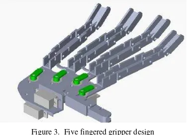
Figure 3. Five fingered gripper design
and thumb. The joints of the finger, the distal interphalangeal (DIP), proximal interphalangeal (PIP) and metacarpophalangeal (MCP) joints each have 1 DOF to provide a rotation movement. The architecture of the five fingers is show in Fig. 3.
The thumb has been designed in order to complete the hand and it has two degrees of freedom. The thumb is both able to flex and extend. The index, middle, forth and little finger prototypes have been designed such that each finger has three degrees of freedom. In order to simulate the finger motions each revolute joint has an associated Servo DC motor attached to it. The extension finger tip is also controlled using a DC motor Servo driving a rack and pinion.
C. Mathematics Model for DC Servo Motor
DC servo motor is used to drive six joints in finger robot. The author presents the mathematics model for DC servo motor as follows.
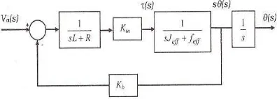
f=Coefficient viscous motor and load, N-/rad/sec The equation 1 is the transfer function of DC servo motor which is used to drive the motor in each finger link. The mathematics model is applied in block simulink and illustrate in Fig. 4.
Figure 4. The transfer function of DC servo motor
D. Trajectory Line
The trajectory planning is necessary to generate the reference inputs to the motion control system, which ensures that the gripper robot executes the planned trajectories. The minimal set of requirement for a gripper robot is to be able to run from an initial position to a final assigned position.
The input of trajectory planning algorithm is the path description, the path constraints and the constraints imposed by a gripper robot dynamics, whereas the outputs are the joint trajectories in terms of a time sequence of the values attained by position, velocity and acceleration.
Position control is used when the robot finger must be moved with or without load along a prescribed trajectory through the mobile robot workspace. The control system of mobile robot is merely a collection of joint controllers
each of which is presented to a single joint to drive it individually. The reference signals for these controllers are supplied by a joint trajectory generator determining the desired joint trajectory from the desired trajectory of the mobile robot.
E. Robust Control Strategy
The control of robot hand is responsible for ensuring that the hand firmly grasps and that corresponding finger in the presence of external forces applied to the object. These forces may require high values of contact force at the fingertip to get the stability response. To solve these problems Kazerooni in 1990 published a control law adopted the relationship between the interaction force and position trajectory [10].
A considerable body of research has been undertaken on robotic hand system with robot force control and planning related to the entire device and the significant developments are as follows,
Okada developed robotic hand to handle objects which is suitable to suppress the rapid change of the grasping condition during a complex finger motion. The finger control consists of a hybrid position/torque servo implemented in hardware. Robot hand Okada has shown to understand and manipulate objects under position control mode [11].
Salisbury had presented control algorithms for achieving the stable force control and involving the relation between position and applied force, stiffness control with feedback of position only and stiffness control with force feedback correction [12]. This force is converted to joint torque commands and the resulting endpoint motions. Force control has been applied to robot hands [13] and [14]. The implementation of a controller and a brief of description of programming language for the Salisbury hand were presented [15]. He introduced the concept of a grasp frame that is calculated as a function of the positions of the finger tips. A summary of issues involved in low level control of the Utah-MIT hand was presented [16].
The impedance control methods are developed for dexterous robot fingers which has relation between velocity and applied force [17]-[18] and [19].
In 1997 DLR’s dexterous four robot hand is designed as a dexterous robot hand with a semi anthropomorphic design. The application of robotics hand systems in unstructured environments required the dexterous manipulation abilities and facilities to perform complex remote operations. Therefore this robot hand has developed both of new design sensors as 6 DOF fingertip force torque sensor and integrated electronics with new communication architecture [20].
The real time control and coordination of the manipulation package (RCCL/RCI) has been adopted in UB robot hand. RCCL/RCI developed for the control of a single robot has been modified in order to cope with peculiar characteristic of the UB hand system [22].
Position control is used when the robot finger must be moved with or without load along a prescribed trajectory through the robot finger workspace. The control system of robot fingers is simply a collection of joint controllers each of which is dedicated to a single joint and drives it individually. The reference signals for these controllers are supplied by a joint trajectory generator determining the desired joint trajectory from the desired trajectory of the gripper.
The joint controller is a feedback controller having two terms respectively proportional to position and velocity errors and introducing proportional and derivative actions (PID control). An advance PID control with auto tuning has been applied to control the kinematics motion in the joint angles of each of the fingers. By tuning suitable values of the three constant gains in the PID controller algorithm, the controller has been found to provide the necessary control action for specific process requirements. The suitable gains of Proportional gain (Kp), Integral (Ki) and Differential gain (Kd) value are determined by auto tuning to achieve a fast response to steady state (setting tune) without excessive overshoot. The error signal is the difference between reference input angle and actual output angle of the system. Parameter Kd works on the change of the error signal, so it can reduce dramatically overshoot effects to reach steady state response.
Figure 5. Robot gripper control
Figure 6. Visualization of griipper finger motion
III. RESULT AND DISCUSSION
A. Simulation Result
The simulation results visualization of gripper five fingers kinematics motion are shown in Fig. 6. In this gripper robot animation, the fingers gripper move to open
and close. In this task there are five position configuration set points of finger which can operate by simulation in Matlab/SimMechanics. Curve signal as input desired is provided in this task to produce the various fingers motion. In this paper, the author’s shows the angular position graph in five fingered gripper robot as shown in Fig. 7.
Figure 7. Simulation of angular position gripper finger control
The various input references are examined into simulation to determine some responses from each actuator in 20 second. The visualization of the motion gripper simulation is show in Fig. 6. The simulation of actual response shows the servo DC motor motion has achieved the steady response at ± 1,301 with minimum overshoot at
±
6,35% .The thumb moves to touch the index finger where an actual angular position in thumb moved from 0o to 70o in 5 seconds. The signal error towards closed less than 1% which it indicates the response dynamic system response is stable.
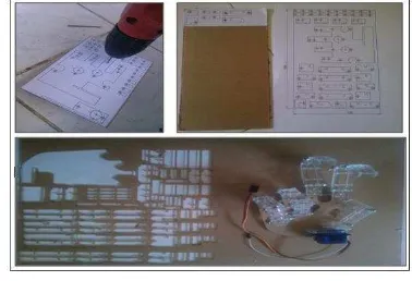
Figure 8. The process of five fingered gripper building
B. Experiment Result
The second method is examination of prototype of the five fingered robot gripper. The process to build of robot gripper prototype can be seen in the Fig. 8.
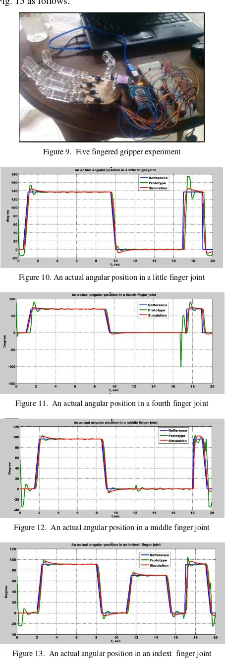
The prototype of five fingered robot gripper is connected to an Arduino Mega AT 2560 as a microcontroller and it shows in Fig. 9 as follows.
experiment process. The actual angular position response into an experiment of robot finger is shown in Fig. 10 to Fig. 15 as follows.
Figure 9. Five fingered gripper experiment
Figure 10. An actual angular position in a little finger joint
Figure 11. An actual angular position in a fourth finger joint
Figure 12. An actual angular position in a middle finger joint
Figure 13. An actual angular position in an indext finger joint
Figure 14. An actual angular position in 1st joint of thumb
Figure 15. An actual angular position in 2nd joint of thumb
The overshoot signal in experiment of prototype is higher than in simulation process because there are many disturbance inputs in experiment process such as torque disturbance, viscous disturbance etc., respectively. When a given reference value is fixed with a long time, small oscillations will occur in prototype testing. While the simulation test looks linear oscillation does not occur. The number of oscillations that occur in the joints of the thumb is due to the weight-bearing joints of the thumb movement. Effects of External mode is used in the initial prototype testing that the motor moves at 90 ° so that the test results is obtained initial chart movements condition is not from zero.
The results of prototype testing showed that the time required to drive the motor is longer than the simulation testing. Prototype testing results are not much different from the simulation test results, that the servo motor takes a few seconds to achieve a given reference angle. The occurrence of oscillations in the prototype test results is caused the sensor to experience disturbances outside the non-linear.
IV. CONCLUSION
The physical model of the five finger robot gripper is built using SimMechanics software and the application Simmechanics has also been verified with identical outputs when compared with Simulink simulations. These studies indicate that each finger of the gripper can be controlled using the robust control of PID formulation. PID control is very effectively used to control the trajectory of the fingers. The simulation results have been demonstrated that the radius of finger movement is achieved in stable response. The signal error towards closed less than 1% which it indicates the response dynamic system response is stable.
error signal in simulation process because there are many disturbance inputs in experiment process such as torque disturbance, viscous disturbance etc., respectively. By using the robust PID control can control the robot gripper with the best performance.
ACKNOWLEDGMENT
We are deeply and invaluable gratitude a Minister Department of Education and Culture Republic of Indonesia for supporting and finding this Decentralizes research (APBN 2015) though Letter of assignment in the contract of implementation of Decentralizes in year 2015:311-160/UN 14.2/PNL.01.03.00/2015
REFERENCES
[1] K. B. Fite, T. J. Withrow, Xiangrongshen, K. W. Wait, J. E. Mitchell, and M. Goldfarb, “A gas actuated anthropomorphic prosthesis for trans humeral amputees,” IEEE Transactions on Robotics, vol. 24, no. 1, pp. 159-169,2008.
[2] K. Kaneko, K. Harada, and F. Kanehiro, “Development of multi-fingered hand for life-size humanoid robots,” in Proc. IEEE International Conference on Robotics and Automation, Roma, Italy, 2007, pp. 913-920.
[3] G. Causey, “Guidelines for the design of robotic gripping systems,”
Assembly Automation, vol. 23, no.1, pp. 18–28, 2003.
[4] A. T. Miller, “A versatile simulator for robotic grasping,” Ph.D. thesis, Department of Computer Science Columbia University, New York, NY 10027, 2001.
[5] L. Zlajpah, “Robot simulation for control design,” Robot Manipulators Trends and Development, Slovenia, 2010, pp. 43-73. [6] K. J. Astrom, PID Controllers: Theory, Design and Tuning, 2nd
edition, Instrument Society of America Research Triangle Park, 2002.
[7] G. D. Wood and D. C. Kennedy, “Simulating mechanical systems in Simulink with SimMechanics,” Technical Report, the Mathworks, Inc, USA, 2003, pp.1-25.
[8] L. Zlajpah, “Simulation in robotics,” Mathematics and Computers in Simulation, Slovenia, vol. 79, no. 4, pp. 879-897, 2008. [9] W. Widhiada, S. S. Douglas, and J. B. Gomm, “Design and
control of three fingers motion for dexterous assembly of compliant elements,” International Journal of Engineering, Science and Technology, vol. 3, no. 6, pp. 18-34, 2011.
[10] H. Kazerooni, B. J. Waibel, and S. Kim, “On the stability of robot compliant motion control,” ASME Journal of Dynamic Systems, Measurements, and Control, vol. 112, no. 3, pp. 417-426, 1990. [11] T. Okada, “Computer control of multi-jointed finger system for
precise object handling,” IEEE Trans. Syst., Man, Cybern, vol. Smc-12, pp.289–299, 1982.
[12] J. K. Salisbury and J. Craig, “Force control and kinematic issues,”
International Root. Res., vol. 1, pp. 4-17, 1982.
[13] Kobayashi, “Control and geometrical considerations for an articulated robot hand,” Int. Journal of Robotics Research, pp. 3– 12, 1985.
[14] T. Yoshikawa and K. Nagai, “Manipulating and grasping forces in manipulation by multi-fingered hands,” in Proc. IEEE International Conference on Robotics and Automation, 1987, pp. 1998–2004.
[15] S. L. Chiu, “Control of redundant manipulators for task compatibility,” in Proc. IEEE International Conference on Robotics and Automation, California, 1987, pp.1718-1724. [16] K. B. Biggers, S. C. Jacobsen, and G. E. Gerpheide, “Low level
control of the utah/M.I.T. dexterous hand,” in Proc. IEEE. Int. Conf. Robotics and Automation, San Francisco, Ca, 1986, pp. 61-66.
[17] R. H. Colbaugh, H. Seraji, and K. Glass, “Impedance control for dexterous space manipulators,” in Proc. 31st Conf. on Decision
and Control, Tucson, Arizona, 1982, pp. 1881–1886.
[18] H. Hanafusa and H. Asada, “A robot hand with elastic fingers and its application to assembly process,” in Proc. Ifacsymp. on
Information and Contr., Problems in Manufacturing Technology, Tokyo, 1977, pp. 127–138.
[19] N. Hogan, “Impedance control, an approach to manipulation,” Int . J. of Robotics Res., vol.107, pp.1–24, 1985.
[20] J. Butterfass, M. Fischer, M. Grebenstein, S. Haidacher, and G. Andhirzinger, “Design and experiences with dlr hand ii,”
Automation Congress, Proceedings, World, vol. 15, pp. 105-110, 2004.
[21] G. Bekey, R. Tomovic, and I. Zeljkovic, Control Architecture for the Belgrade/Usc Hand in Dextrous Robot Hands, New York: Springer-Verlag, 1999, pp. 136-149.
[22] A. C. Eusebi, C. Fantuzzi, and C. Melchiorri, “The U.B. hand ii control system,” IEEE Transactions on Robotics and Automation, pp. 782-787, 1994.
Wayan. Widhiada, ST, MSc, PhD has
worked as a lecturer in Mechanical Engineering Department, Engineering Faculty of Udayana University, Denpasar, Bali, Indonesia since 1996.He was born in Badung, Bali, Indonesia on 19 November 1968.He completed Postgraduate Doctor Program in Mechanical Engineering at School Engineering of Liverpool John Moores University-United Kingdomon November 2012. His study research is about Robotic and control.
He focuses to develop the research in robotic and control research. He was a reviewer paper in IEEE/RSJ International Conference on Intelligent Robots and Systems 2014.
Tjokorda Gde Tirta Nindhia was born in
Denpasar, Bali, Indonesia on January 16th,
1972. Received Doctor Degree in Mechanical Engineering from GadjahMada University (UGM) Yogyakarta, Indonesia on August 2003, with major field of study was Material Engineering. He participated in various international research collaboration such as with Muroran Institute of Technology Japan(2004), Toyohashi University of Technology Japan (2006), Leoben Mining University Austria (2008-2009), Technical University of Vienna Austria (2010) and Recently with Institute Chemical Technology of Prague Czech Republic (2012-now). His current job is as Full Professor in the field of Material Engineering at Department of Mechanical Engineering, Engineering Faculty, Udayana University, Jimbaran, Bali, Indonesia. His research interest covering subjects such as, biomaterial, waste recycle, failure analyses, ceramic, metallurgy, composite, renewable energy, and environmental friendly manufacturing.
Prof. Nindhia is a member of JICA Alumni, ASEA-UNINET alumni, International Association of Computer Science and Information Technology (IACSIT), Asia-Pacific Chemical, Biological & Environmental Engineering Society (APCBEES) and also member of association of Indonesian Nanotechnology. Prof Nindhia received best researcher award in 1997 and in 2013 fromUdayana University the place where he is working and again in 2012 received both Best lecturer award from Engineering Faculty of Udayana University. In the same years 2012, The research center of Udayana university awarded Prof Nindhia as the best senior researcher. In 2013 Prof. Nindhia awarded as 15 best performance Indonesian lecturers from Ministry of Education and Culture The Republic of Indonesia.
Nyoman Budiarsa, MT, Ph.D is an associate
Information Technology), WASET (World Academy of Science Engineering and Technology), ISAET (International Scientific Academy of Engineering & Technology).Active participation in the Scientific Committee and as editor for several International conferences. until now active in teaching and in the organization or association in their fields, especially in the field of Material Characterization, Surface