Analysis of the Application current X2 Interface Handover Process
in LTE Technology
Uke Kurniawan Usman
Department of Electrical and Telecommunication Engineering Telkom University
Jl. Telecommunication No.1 Bojongsoang BANDUNG [email protected]
Abstract - LTE (Long Term Evolution) is a 4G technology which is in the developmental period. In its development we need to know the integrity of LTE networks in providing reliable service of the mobility when service users, so we need to discuss the handover process that occurs in LTE, where this handover process will determine the ability of communication networks in maintining the communication link is going.
Problems arise when we talk handover is how the data transfer process occurs in LTE. X2 is an interface that must be passed whentheprocess of transferring data of time of handover between two eNodeB adjacentpieces in LTE. The capabilities of interface X2 also makes effect to maximization of the function on handover process, so it is necessary to analyze the function of interface X2 when handover happen between eNodeB in LTE. This research can be seen that the LTE quaranteering handover process when through on X2 interface at high speed that is greater than 60 km/hour. The existence makes use of the time required to performs faster handovers, seen from simulation result with TTT = 0,034 ms , Hom = 2,029 dB and TTD = 0,165 ms at speed 200 km/hour and angle direction of movement of user is 00
dan 600 . In addition , the faster movement of the user, the smaller
the time required to perform handovers because the user through the area or areas slices cell or cell handovers
Keywords: Interface X2, TTD, TTT, TP and HOM
I. INTRODUCTION
User mobility affect dynamic changes about network quality sue the continuity of network telecommunication service, therefore a good handover mechanism is needed to maintain network performance. Handover is an important aspect in mobile radio system to ensure the unestablished connection will still connected even the user moves. We have to notice the handover reliability also. Handover speed in LTE is affected by X2 interface. Which is, the X2 Interface is a hanover interface between two close eNodeb in LTE system.
II. LTE ( LONG TERM EVOLUTION ) [1] [2] [3]
Long Term Evolusion (LTE) has radio access and core network used for reduce network latency and improve system performance and provides interoperability with existed 3GPP technology and non-3GPP.
Picture 1. LTE Network Architecture Network architecture of LTE, as you can see above, built more simple than previous networks. Overall LTE architecture consist of several eNodeB that provides access from UE to EUTRAN trough EUTRA. X2 as interface between eNodeB.
MME/SAE gateway provides connection between eNodeB and EPC with S1 interface. X2 and S1 are support UE and SAE gateway. Both also provide dynamic scheduling from UE and data stream. Other important service from eNodeB are header compression dan encryption from user data stream.
III. HANDOVER Proccess [1] [2]
Handover process starts while MS detect pilot signal that significantly strongest among other forward traffic channel addressed to it. The MS will send pilot measurement message to the base station with the strongest signal and instructing to start handover process. The Cell site will send handover direction to MS and direct it to start handover process. After execute handover message MS will send handover completion message on the new traffic reverse channel.
a.Handover between eNodeB trough Interface X2 in LTE [6] [7] Handover system that occur between BTS in 3G have to be trough BSC first. The Handover that occur trough BSC has some weakness, such as big latency, long delay and big chance of loss handover.
While in LTE used a simpler intra handover system. We can see it from handover process between 2 close eNodeB (BTS for GPRS), between two handover that directly connected by an X2 interface.
UE Target LTE eNodeB Source LTE
eNodeB MME / S-GW
1. Provision of area restriction 2. Measurement control 3. Handover decision
4.HO request
5. Resource setup
7. HO command
6. HO request ACK
8. Status Transfer
9. HO complite
10. Path switch Request
11. Path switch request ACK
12. Release Resource
Picture 2. Handover procedures in LTE
IV. INTERFACE X2 [6]
Interface X2 is an interface protocol structure used for mobility function occurs between two close eNodeB, it is handover process included. Transfered data trough eNodeB is a specific data from user. X2 interface has interface control and user plane control function. Interface control uses SCTP (Stream Control Transmission Protocol) between two eNodeB, This SCTP sustain delivering data process. Image about X2 interface showed below:
eNodeB eNodeB eNodeB eNodeB
X2AP X2AP GTP - U GTP - U
SCTP IP L2
SCTP IP L2
SCTP IP L2
SCTP IP L2
L1 L1 L1 L1
Picture 3. X2 interface configuration[6]
Mostly, X2 Interface only used for control plane information while handover connection occur, but nowadays it is used for forwarding user data that handovering. Transmission between eNodeB in control plane using SCTP (Stream Control Transmission Protocol) while transfer data occurs. While UDP (User Datagram Protocol) is data form that planed to be transferred while handover is going to be excecuted. X2 set the signaling, these are X2 interface function :
1. Mobility management Intra-handover
2. Coordination from resource, overload,and traffic status. 3. Setting up and Resetting from Interface X2
4. Errors handling.
For LTE, while handover is going to be occur between two eNodeB, then there will be direct handover between Source eNodeB (SeNodeB) and Destination eNodeb (TeNodeB). Source SeNodeB will directly send handover request and start time calculation, after getting Request handover Acknowledge then handover is occur (if it doesn’t exceed the time allowed) and there will be a grounding handover process (if exceed the time allowed).
V. Modelling System
In this modeling system for handover application simulation trough X2 Interface used coverage cell model with hexagonal shape with amount of observed cell are two close cells of LTE service. System modeling used in this research as seen on picture below :
eNodeB
eNodeB
User Movement
Picture 4. System Model
VI. FLOWCHART SCENARIO SIMULATION To facilitate designing process on simulation requires a flowchart for understanding designing process that was made. This Flowchart contains steps of designing process for knowing several handover process trough X2 Interface in LTE, as seen on picture below:
START
END Sel Sumber (eNodeB
sumber)
HO terjadi ke sel tujuan baru
Sel Tujuan (eNodeB sumber)
Jika 2 Level Daya = HO Jika 1 Level Daya = no HO N
DROP
Pengukuran Level Daya
Perhitungan Delay yang diperbolehkan
Y
Y
Jika HO Margin > Level Daya = no HO Jika HO Margin < Level Daya = HO
N
Y
Picture 5. Flow Simulation
In the beginning of the process, system detecting any power level in this process, then will be a measurement of power level and report from ME to BS, so that the BS detect a power level acceptance. If there are 2 power level in process and differenciate, so the process will proceed to review parameters, if there is only 1 power level the process will terminated right on that spot. Placement of the first parameter TTT, which is this parameter has responsibility to observe delay for 2 signal, if the best condition reached,it wil go to next parameter. If it can’t obtain the best condition it will go back to the process. (Level Power Management). Once completed the first parameter, the system will continue the process to HO parameters, this parameter serve to see the value in HO margin. If the margin is greater than the power level value, HO process will stop and return to the TTT, but if the margin less than or equal to the value of power level, system will display a confirmation report, then the system will display the visualization HO process.
Decision
Measurement
VII. Simulation Parameter Used Distance Parameter MS to BTS
This parameter is used to measure the distance between MS to BTS. The point is knowing the position of user, the shortest distance to BTS, as an input to the received power level.
The distance between MS and BS are currently serving or position of the MS to the BS in the direction of the x axis and y can use the equation as shown in Figure 6 below:
r = (
(
−
) + (
−
)
)
...(1st equation)information: X1 : koordinat x MS X2 : koordinat x BS Y1 : koordinat y MS Y2 : koordinat y BS
Picture 6. Distances Parameter (3.4)
When the MS moves from one point to another it will be measured within the time frame specified, MS is closer to the serving BS or closer to another BS. If the distance between serving MS to BS is minimum, then the call will go on and served by the BS. But if the distance is far and into the area threshold then the handover will be triggered and the nearest BS MS BS will take over the role previously to serve MS.
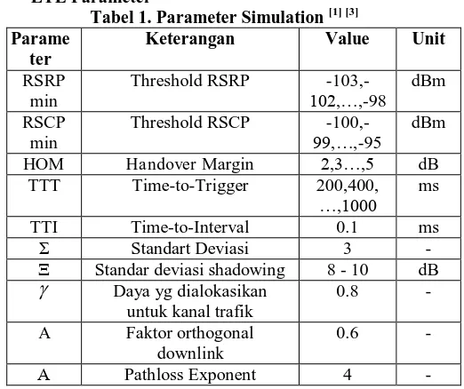
LTE Parameter
Tabel 1. Parameter Simulation [1] [3] Parame
ter
Keterangan Value Unit
RSRP min
Threshold RSRP
-103,-102,…,-98
dBm
RSCP min
Threshold RSCP
-100,-99,…,-95
dBm
HOM Handover Margin 2,3…,5 dB TTT Time-to-Trigger 200,400,
…,1000 ms
TTI Time-to-Interval 0.1 ms
Σ Standart Deviasi 3 -
Ξ Standar deviasi shadowing 8 - 10 dB
Daya yg dialokasikanuntuk kanal trafik
0.8 -
A Faktor orthogonal downlink
0.6 -
Α Pathloss Exponent 4 -
VIII. Simulation Process
a. Simulation Input
This simulation conducted observations of users that move from cell LTE source to LTE destination. Input is a simulation
form the direction and different user’s speed with initial position
of the user is at the center of the cell LTE. Analyzed user speed is 5 km / h, 15 km / h, 30 km / h, 60 km / h, 90 km / h, 120 km / h, 150 km / h and 200 km / h while the angle made by the movement angle of 0 °, 10 °, 20 °, 30 °, 40 °, 50 ° and 60 ° (over or handover overlap area between two cells).
b. Simulation Output
Output in this simulation is to observe the value of the minimum time required for the handover through the X2 interface. Where the results are seen from the relationship between the speed and direction of user’s movement, left or go to a cell. All of it can be seen from the value of TTT (Time To Trigger), TP (Time process) and TTD (Time Data Transfer) and the number of iterations for each speed has been specified. Once established, it will be the selection of the best combination of parameters, so that the handover has a minimum time of handover, where the amount of the value of time was expected to be no delay.
IX. Analysis of the scenario testing systems using X2 interface
When doing communication, user measure RSRP signal strength received from the Node B serving cell and the signal received from the RSRP node B neighbor cells. It is necessary for the system to determine whether the user is still able to be served by the serving cell or should be handover to a neighbor cell. Ongoing communication so that not having dropping, we need a combination of values in both cell RSRPmin, handover margin and Time-to-Trigger is best as a reference to generate the minimum value of the handover when the user moves.
Here is the parameter analysis based on scenario that was explained above :
a. Direction of movement angle 00
Simulations were performed using an angle 00 from user’s movement to the cell during a handover destination with speed 5km/h, 15km/h, 30km/h, 60km/h, 90km/h, 120km/h, 150km/h and 200km/h the distance of 2 km.
Here is the result of simulation as seen in figure 7:
Picture 7 Simulation Result on Direction of the User 00 In figure 7 shows that the magnitude of the minimum time required for the handover occurs through X2 interface of 0.165 ms at a speed of 200 km / h. From the change of pace, the user obtained the higher the user’s speed it will get minimum time required to perform data transfer time of the handover through the X2 interface. This happens because the time required by the user to go through the faster handover area. The faster movement also causes HOM as margin requirements before serving cell neighbor moved into the target cell more quickly, seen with a TTT = 0.034 ms.
b. Direction of Movement Angel 100
Here is the result of simulation as seen in figure 8 with 10°: 0,000
20,000
5 30 90 150
T
T
D
(
m
s)
Speed of User (km/jam)
Direction of Movement
0
0
TTD
TP
Picture 8. Simulation Result on Direction of the User 100 In figure 8 it was clear that the minimum time required for handover in determination and delivery process through the X2 interface user data was at 0.186 ms at a speed of 200 km / h. TTD value that decreases with increasing pace suggests higher user speeds it will get the minimum time required to perform data transfer time of the handover through the X2 interface. This is because the time required by the user to go through the fast handover area. So is the value of TTT that happens, the faster movement also causes HOM as margin requirements before serving cell neighbor moved into the target cell more quickly met, seen with a TTT = 0.036 ms.
c. Direction of Movement Angel 200
Here is the result of simulation as seen in figure 9 with 20°:
Picture 9. Simulation Result on Direction of the User 200 In figure 9 shows that the minimum time for a handover process through X2 interface can happen at a speed of 200 km / h for TTD = 0.202 ms. TTD value that decreases with increasing pace suggests higher user’s speeds, it will get the minimum time required to perform the data transfer time of the handover through the X2 interface. This is because the time required by user to go through the fast handover area. So the value of TTT happens, the faster movement also causes HOM as margin requirements before serving cell neighbor moved into the target cell more quickly met, seen with a TTT = 0.030 ms.
d. Direction of Movement Angel 300
Simulations using 30° angle to the user moving the cell at the time of handover destination with speed 5km/h, 15km/h, 30km/h, 60km/h, 90km/h, 120km/h, 150km/h and 200km/h at a distance Flight 2 km, and RSRP value = -99 dBm
Here are the simulation results shown in figure 10 below:
Picture 10. Simulation Result on Direction of the User 300 In figure 10 shows that the minimum amount of time required for the handover process through X2 interface is 0.206 ms at a speed of 200 km / h. From the change of pace the user obtained, the higher the speed so that the user it will get the minimum time required to perform the data transfer time of the handover through the X2 interface. This happens because the time required by the user to go through the faster handover area. The faster movement also causes HOM as margin requirements before serving cell neighbor moved into the target cell more quickly, seen with a TTT = 0.029 ms
e. Direction of Movement Angel 400
In movement direction 40° can be seen that the minimum time for a handover process through X2 interface can happen at a speed of 200 km / h for TTD = 0.202 ms and the value of TTT = 0.030. A similar ms. The result we saw happening at the direction of the current simulation 20° angle. This happens because when the direction of motion was 20° and 40°, the distance between the source user to the cell nucleus and the nucleus of the cell is the same purpose..
f. Direction of Movement Angel 500
The yield on the current direction of the user’s movement was 50° with the current direction of the user’s movement was 10°, with a value of TTD = 0.186 ms and TTT = 0.036 ms. This value is due to the user within the cell source and destination are the same cells.
g. Direction of Movement Angel 400
The yield on the current direction of the user’s movement was 60° with the current direction of the user’s movement was 0° with the TTD value = 0.165 ms and the value of TTT = 0.034 ms. This happens because the distance of the user from the source cell and the destination cell are the same between 60° and 0° directions
X. Simulation without Interface X2
Simulations are performed using the same parameters when the user speed are 0 km / h, 10 km / h, 20 km / h, 30 km / h, 40 km / h, 50 km / h, 60 km / h and the distance the user movement 2km. The comparison result of the handover without going through the X2 interface and through the X2 interface as shown in figure 11 below:
0,000 20,000
T
T
D
(
m
s)
Speed (km/hour)
Direction of Movement
10
0
TTD
TP
TTT
0,000 5,000 10,000 15,000 20,000
5 15 30 60 90 120150200
T
T
D
(
m
s)
Speed of user (km/jhour)
Direction of Movement 20
0
TTD
TP
TTT
0,000 20,000
T
T
D
(
m
s)
Speed of User (km/hour)
Direction of Movement
30
0
TTD
Picture 11. Comparison of TTD value with or without X2 interface
From Figure 11 shows that the time required to perform handover when without using the X2 interface (0.430 ms) was longer than when using the X2 interface (0.165 ms). Difference is due when the handover without using the X2 interface handover process which will occur longer, in terms of the participation of the MME in the handover process, so it will be more delay occur. Meanwhile, handover occurs through X2 interface, there will be a handover that involves only two directly adjacent eNodeB.
XI. Overall Simulation Results
From the overall results of the simulation has been done analyzing the simulation results obtained are as follows: 1.TTD values (Data Transfer Time) via the X2 interface that
ranged from 0.165 ms - 8.218 ms, and the best times occur when the direction of 0° and 60° angle is equal to 0.165 ms at a speed of 200 km / h.
2. TTD values without through X2 interface ranged from 0.430 ms - ms 16.536, and the best times happen at the speed of 200 km / h and movement angles 0° and 60° is 0.430 ms. This value is passed by value are allowed on LTE
3.Value TTT (Time To Trigger) required to generate a handover was achieved HOM value allowed on LTE (Long Term Evolution) ranging from 0.029 ms - 1.402 ms. TTT best value occurs at the speed of 200 km / h and the direction of the 300 is 0.165 ms.Hal can be caused by the user to move directly from the source cell to the destination cell with the fix angles. Changes of TTT (Time To Trigger) value growing rapidly occurring every this is due to increased speed of analysis calculation time on set 0.1 s, where the simulation program will read every movement of the user at every 0.1 s, but it is also a relevant result which if the user doing the faster movement is automatically time will trigger sooner, as seen in the table. the values that are allowed on LTE.Nilai HOM HOM is stable, while the movement of the user's growing fast.
XI. Conclusion the direction of the velocity are 0° and 60° angle. This is due to the higher speed of the user, the time taken to pass through the area the faster handover.
2.TTD minimum value when the handover occurs without going through the X2 interface at a speed of 200 km / h and the angle 0° and 60° of user’s movements. TTD value through X2 interface faster than the X2 handover without going through the interface. The difference in the value of TTD dues when the handover occurs without going through X2 interface, then the handover will take place through the MME, which means the greater the value of delay that occurred.
3.Value TTT (Time To Trigger) required to generate a handover (HOM values achieved are allowed on LTE) of 0.029 ms at a speed of 200 km / h at an angle of 30°. This is because the angle will affect the movement of the user within the source cell nucleus and the destination cell nucleus.
4.The result of the change in the value of HOM db obtained approximately 2.001 - 2.175 db, this is in accordance with the standard on LTE (2-5 db). The results of this experiment also showed that HOM stable value when the user speeds greater than 60 km / h.
5.LTE guarantee the handover at high speeds are greater than 30 km / h. The handover is initiated when the user handover coverage area, and marked the start computed TTT value in achieving HOM allowed on LTE, and subsequently calculated the value TTD mark the handover process. Handover occurs Handoff Margin (HOM) in Cellular Communication Systems Long Term Evolution ", thesis Telkom IT Telecommunications Engineering 2011.
[3] Holma, Harri, Antti Toskala. LTE for UMTS: OFDMA and SC-FDMA Based Radio Access. John Wiley & Sons. United Kingdom. 2009.
[4] Gunawan, Arief Hamdani. Slide Seminar LTE. 2010. [5] Sesia,Stefania, Issam Toufik dan Matthew baker. LTE :THE
UMTS LONG TERM EVOLUTION. John Wiley & Sons. United Kingdom. 2009