ROBUST VISION-BASED POSE ESTIMATION ALGORITHM FOR AN UAV WITH
KNOWN GRAVITY VECTOR
V. V. Kniaz a*
a
State Res. Institute of Aviation Systems (GosNIIAS), 125319, 7, Victorenko str., Moscow, Russia - [email protected]
Commission V, WG V/1
KEY WORDS: UAV, machine vision, external orientation estimation, motion capture system
ABSTRACT:
Accurate estimation of camera external orientation with respect to a known object is one of the central problems in photogrammetry and computer vision. In recent years this problem is gaining an increasing attention in the field of UAV autonomous flight. Such application requires a real-time performance and robustness of the external orientation estimation algorithm. The accuracy of the solution is strongly dependent on the number of reference points visible on the given image. The problem only has an analytical solution if 3 or more reference points are visible. However, in limited visibility conditions it is often needed to perform external orientation with only 2 visible reference points. In such case the solution could be found if the gravity vector direction in the camera coordinate system is known. A number of algorithms for external orientation estimation for the case of 2 known reference points and a gravity vector were developed to date. Most of these algorithms provide analytical solution in the form of polynomial equation that is subject to large errors in the case of complex reference points configurations. This paper is focused on the development of a new computationally effective and robust algorithm for external orientation based on positions of 2 known reference points and a gravity vector. The algorithm implementation for guidance of a Parrot AR.Drone 2.0 micro-UAV is discussed. The experimental evaluation of the algorithm proved its computational efficiency and robustness against errors in reference points positions and complex configurations.
1. INTRODUCTION
The problem of external orientation estimation is one of the central problems in photogrammetry and computer vision. It could be stated as an estimation of six parameters of the external orientation that define the spatial position and orientation of the camera coordinate system with respect to the global object coordinate system (Luhmann et al., 2014). This problem is commonly known as the problem of camera calibration. In computer vision society this problem is sometimes referenced as Perspective-n-Point (PnP) problem, where n represent the number of available reference points.
1.1 Related work
It was shown by (Fischler and Bolles, 1981) that at least 3 reference points are required to find a solution to pose estimation problem. However direct solution for P3P problem may not be found from weak reference point configurations. A direct solution for P4P problem for arbitrary reference point configuration was proposed in (Abidi and Chandra, 1995). A large number of algorithms were developed for solution of PnP problem with n≥ 4. Such algorithms are more robust against noise in the detected reference points positions but require an iterative approach to solve an overdetermined system of equations. Hence the computational complexity of state-of-the-art PnP algorithms usually has a O(n5) relation with respect to time.
In (Lepetit et al., 2008) a non-iterative robust EPnP algorithm for n ≥ 4 was proposed. Due to the non-iterative approach the computational complexity of EPnP grows linearly with respect
*
Corresponding author
to n. A different approach to the PnP problem utilizing an error metric based on collinearity in object space (as opposed to image) is proposed in (Lu et al., 2000). The LHM iterative algorithm is based on this approach and provide a fast and globally convergent solution for PnP problems with n≥ 3.
All methods presented above perform the pose estimation using only the information about the reference points positions in the object space and their projections in the image space. However even human operator may have problem with an interpretation of a scene on an image that was captured with unnatural camera orientation (i.e. zenith direction or local gravity vector doesn’t coincide with the vertical axis). In contrast, any human usually has no problem with interpretation of the scene that he perceives by his vision. However, human vision system has a hint for estimation of the head rotation because the direction of local gravity vector is provided by the vestibular system.
function of the unknown rotation angle the solution may become unstable when the unknown angle is close to 90°.
Another solution for P2P problem with known gravity vector direction is proposed in (D'Alfonso et al., 2014). In this method it is assumed that both camera and object with reference points are equipped with sensors that provide the orientation of gravity vector. Hence pose estimation with respect to a moving object is possible. The performance of the method is close to the performance of uP2P. However, estimation of the rotation angle is also unstable if the angle is close to 90°.
Pose estimation for an arbitrary configuration of 2 points is often required in practical applications such as initial estimation of parameters for bundle adjustment or UAV autonomous flight. It is obvious that if 2 points are projected into a single point in the image, the pose of the camera couldn’t be estimated. Such weak configuration occurs if the line that connects 2 points is normal to the image plane. Direct solutions of collinearity equations for weak configurations are generally unstable.
However, the robustness of the solution could be improved if the estimation of the rotation angle will be performed using homogenous coordinates on a unit sphere. Such approach is widely used for vanishing point detection and rotation estimation (Barnard, 1983), (Kalantari et al., 2008), (Förstner, 2010). This paper is focused on the development of a new algorithm for Minimal number of points Linear pose estimation with known Zenith direction (MLZ). The MLZ algorithm provide robust P2P pose estimation for weak configurations of reference points2.
1.2 Paper outline
The rest of the paper is organized as follows: in the second part the developed MLZ algorithm is presented. The problem statement is given and unit sphere based rotation angle estimation is discussed. The second part is concluded with the solution of the pose estimation problem and the algorithm pipeline. The third part is dedicated to the experimental evaluation of the algorithm using a computer simulation and a Parrot AR.Drone 2.0 micro-UAV. The paper is concluded with the analysis of the experiments and prospects for further research.
2. MLZ ALGORITHM
2.1 Problem statement
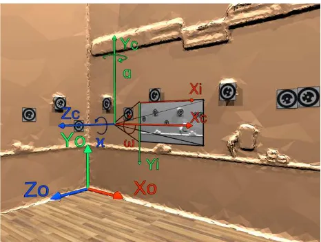
Assume a camera and two reference points in the field of view of the camera. Three coordinate systems are defined. Object coordinate system ОoХoYoZo is related to some object of interest in the observed scene and defined as follows: ОоХоZоplane is normal to gravity vector, the Yоaxis is normal to Хо, Zоaxes. The point of origin is related to some point of the observed scene and is selected appropriately for a given problem (figure 1).
The origin of the image coordinate system ОiХiYiZi is located in the upper left pixel, the Xi is directed to the right, the Yi axis is directed downwards.
The origin of the camera coordinate system ОcХcYcZc is located in the perspective center, the Xc axis is collinear with the Xi axis, the Yc axis is collinear with the Yi axis, the Zc axis is normal to Xc and Yc axes. The rotation of the camera coordinate system
2
The C++ implementation of the algorithm presented in this paper is available online at https://github.com/vlkniaz/MLZ
with respect to object coordinate system is defined using rotation matrix Roc:
�"#= �&∙ �(∙ �), (1)
where Rα– rotation matrix around the axis Y, R⍵– rotation matrix around the axis X,Rϰ– rotation matrix around the axis Z.
Figure 1. Coordinate systems
The developed algorithm should provide an accurate estimation of the camera external orientation for a given pair of reference points X0, X1, with known coordinates in image space x0, x1and known direction of a gravity vector in the camera coordinate system provided as rotation angles � and �. The estimation should be robust against outliers in coordinates of reference points in image space and weak configurations of reference points.
2.2 Unit sphere based rotation estimation
The unit sphere mapping provides a method to avoid singularity during estimation of the position of a vanishing point. In (Barnard, 1983) a method for camera rotation estimation based on pairs of parallel lines in object space is proposed. Each pair of parallel lines is projected onto a unit sphere with a center in the perspective center. Each projection is contained by a plane that intersect the center of a unit sphere. A vector from the center of the sphere to the point of intersection of planes gives a direction vector of parallel lines in the camera coordinate system. Hence the rotation of the camera with respect to a given pair of parallel lines could be found.
� = tan01 023
24, (2)
� = � × �,
� = ��′ × ��′,
� = 0 1 0
,
where n is a cross product between direction vectors x1’, x2’ on the unit sphere, m is a cross product between the unit vector y and the vector n.
Figure 2. MLZ rotation estimation for a case when line L is coplanar to plane ОcХcZc
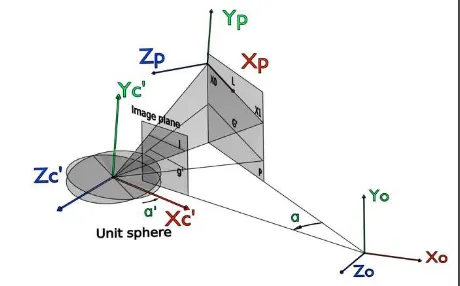
To find the rotation angle for a general case let us introduce ancillary coordinate systems ОpХpYpZp, Оc0Хc0Yc0Zc0 and Оc’Хc’Yc’Zc’ (figure 3). The origin of the point coordinate system ОpХpYpZp is located in the point X0, the Xp axis is parallel to line L, the Yp axis is coplanar with plane P and normal to the axis Xp, the Zp is normal to Xp, Yp axes. Let Rop be the rotation matrix from the object coordinate system to the point coordinate system. Let Roc0 be the rotation matrix from object coordinate system to camera coordinate system in the case when angle α is equal to zero, and angles ω and ϰ are known. Then the coordinate system
Оc0Хc0Yc0Zc0 could be found by rotation of the coordinate system ОoХoYoZo with the matrix Roc0. The coordinate system
Оc’Хc’Yc’Zc’ could be found by rotation of the coordinate system Оc0Хc0Yc0Zc0 with the matrix Rop.
Figure 3. MLZ rotation estimation for a general case
Let a line G’ be the line of intersection between the plane P and the plane Оc’Хc’Zc’. As planes ОpХpZp and Оc’Хc’Zc’ are coplanar the line G’ is parallel to the line L. Let the rotation angle α’ define
the rotation matrix Rc’p with respect to the axis Yc’ from the coordinate system Оc’Хc’Yc’Zc’ to the coordinate system ОpХpYpZp. The the angle α’ to could be found using the projection g’ of the line G and the line l using equation (2).
The final rotation matrix from the object coordinate system to the camera coordinate system could is given by:
�"#01= �"?01∙ �#@?∙ �"?∙ �"#A (3)
2.3 Determination of the perspective center
To find the location of the perspective center O in the object coordinate system, direction vectors x0’, y0’ in the camera coordinate system could be used. Let Xc0, Xc1 be the direction vectors given by rotation of vectors x0’,y0’ with rotation matrix Roc-1:
���= �"#01∙ ��′,
���= �"#01∙ ��′ (4)
The point of intersection of lines l0 and l1 from points X0, X1 defined bydirection vectors Xc0, Xc1 correspondingly will give the location of the perspective center O. In real cases lines l0,l1 will be skew due to measurement errors. Then the position of perspective center O could be defined as:
� = ���F���
G , (5)
where ���, ��� – end points of the perpendicular between lines l0 and l1 (Luhmann et al., 2013):
���= �A+ �
�A
�A
�A
, ���= �1+ �
�1
�1
�1 , (6)
where a0, b0, c0 – direction cosine of the line l0; a1, b1, c1 – direction cosine of the line l1:
�A
�A
�A
= ��� ��� ,
�1
�1
�1
= ���
��� , (7)
� = −
PQ0PR SQ0SR TQ0TR
U V #
UR VR #R UQ VQ #Q UR VR #R
U V #
,
� = −
PQ0PR SQ0SR TQ0TR
U V #
UQ VQ #Q UQ VQ #Q UR VR #R
U V #
, (8)
� = �A �A �1 �1
, � = �A �A �1 �1
, � = ��A �A
1 �1. (9)
X0, X1 except the case when the line l crosses the center of the projection (i.e. except the case when lines l and g’ coincide).
3. ALGORITHM EVALUATION
To evaluate the MLZ algorithm both real experiments and computer simulation were used. Experiments were performed using a Parrot AR.Drone 2.0 micro-UAV and an external motion capture system. The position of the UAV was measured independently by the motion capture system and the MLZ algorithm. Bellow the configuration of the evaluation system is presented.
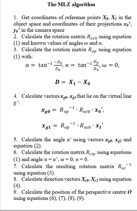
The MLZ algorithm
1. Get coordinates of reference points X0, X1 in the object space and coordinates of their projections x0’,
y0’ in the camera space
2. Calculate the rotation matrix �"#A using equation (1) and known values of angles ω and ϰ.
3. Calculate the rotation matrix �"? using equation (1) with:
6. Calculate the rotation matrix �#@? using equations (1) and angle α = α’, ω = 0, ϰ = 0.
7. Calculate the resulting rotation matrix �"#01
using equation (3).
8. Calculate direction vectors Xc0, Xc1 using equation (4).
9. Calculate the position of the perspective centre O
using equations (6), (7), (8), (9).
Table 1. The MLZ algorithm
3.1 System configuration
The Parrot AR.Drone 2.0 UAV is a quadcopter equipped with two cameras. The first camera is forward looking and provide 720p video at 20 fps. The second camera is directed downwards and provide 320p video at 60 fps. For evaluation of the algorithm the forward looking camera was used. The quadcopter is also equipped with a precise 3 axis gyroscope that provide an accurate measurement of angles ω and ϰ (pitch and roll angles). Technical specifications of the AR.Drone 2.0 UAV are presented in table 2.
3.2 Motion capture system
To record the ground truth position of the UAV with respect to the object coordinate system the ‘Mosca’ motion capture system was used (Knyaz, 2015). The ‘Mosca’ system could provide the information about the UAV position and its rotation with high accuracy and high sample rate.
Unit Parameter Value 3 axis gyroscope Precision 2000°/с
3 axis accelerometer Precision +/-50 mg 3 axis magnetometer Precision 6° Pressure sensor Precision +/- 10 Pa
Ultrasound altimeter - -
WiFi interface Speed b, g, n, up to 54 Mb/s
4x LED lamps Color Red/green
Table 2. Technical specifications of AR.Drone 2.0 UAV
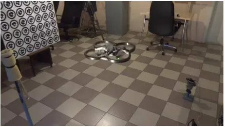
The system includes up to four IEEE 1394 cameras that work in a synchronized mode at a frame rate up to 100 frames per second under the control of a personal computer (PC). The PC provides the possibility for accurate calculation of 3D coordinates of points of interest. The assembled system is shown on figure 4. The system could be extended to more cameras by including an additional PC station in the system. The control commands for the UAV are sent using WiFi interface. The synchronization is established by turning on LED lamps on the UAV at the beginning of the capture session. Technical characteristics of the motion capture system are presented in table 3.
Camera resolution 656 x 491 pixels
Acquisition speed up to 100 fps
Number of tracking points up to 200
Working space 2m x 2m x 2m
3D point coordinate accuracy 0.2 mm
Table 3. Technical characteristics of the motion capture system An original camera calibration and external orientation procedure was used to reach a high accuracy of 3D measurements. The calibration procedure is highly automated due to applying original coded targets (Knyaz, 2010) for identifying and measuring image coordinates of reference points. The system
calibration provides accuracy of 0.01% of working area of the
motion capture system.
The external orientation of the motion capture system is performed after choosing a working space and a camera configuration for motion capture. For an external orientation a special test field is used. It defines the object coordinate system in which 3D coordinates are calculated. For registration of the UAV flight a flat upright standing test field was used.
Figure 4. Assembled motion capture system, the test field and Parrot AR.Drone 2.0 UAV
To register the flight a set of circular targets was located on the bottom side of the UAV. They define the UAV coordinate system
ОuХuYuZu. The targets #1, #2 defines the Zu axis. The origin of
the coordinate system is located between points #1 and #2. The
Xu axis passes through the point #3. The Yu axis is normal to Xu,
Yu. The transformation from the UAV coordinate system to the camera coordinate system was estimated using a calibrated stereo image pair (figure 5).
Figure 5. Orientation of the UAV coordinate system with respect to the UAV frame and circular targets. The UAV lies
upside down, the bottom side is visible
3.3 Algorithm evaluation using an UAV
To evaluate the performance of the UAV the algorithm was implemented in a dedicated software for quadcopter guidance. Two kind of experiments were performed: a hovering flight and a flight along the given trajectory. For both experiments the MLZ algorithm provided the information about UAV position and rotation. A simple feedback control based on the distance between the next waypoint and the estimated UAV position was used.
Two reference points are required as the input for the MLZ algorithm. During the flight experiment reference points were detected automatically at 18 FPS using circular targets detection algorithm. The coordinates of circular targets were calculated with sub-pixel accuracy. To compensate the significant distortion of the frontal camera lens Brown-Conrady distortion model was used (Brown, 1966). Two reference points were chosen from the test field. Hence the object coordinate system of the MLZ algorithm coincided with the motion capture coordinate system. Such approach simplified the processing of the sequences recorded by the motion capture system.
10 hovering flight sessions and 10 flight along a simple trajectory sessions were recorded. The initial position of the UAV for each experiment was 1000 mm from the test field along Zo axis. The
selected trajectory has a form of a rectangle in the plane ОoYoZo with a side of 800 mm. For each session coordinates of the camera estimated by the MLZ algorithm were recorded. The position and the rotation of the UAV were estimated using recorded coordinates. The averaged measurement errors for all sessions are summarized in table 4.
σX (m) σY (m) σZ (m) σα (°) Hovering
flight 0,0121 0,036 0,074 0,85
Trajectory
flight 0,0527 0,061 0,093 1,57
Table 4. Pose and rotation measurement error of the MLZ algorithm
Figure 6 shows two trajectories of the UAV. The first trajectory was recorded by the motion capture system. The second trajectory was estimated by the MLZ algorithm. The analysis of the trajectories proves that the algorithm was accurate enough to guide the quadcopter along the desired trajectory. The distortion of the box trajectory was caused by an insufficient controllability of the UAV with a simple feedback control.
Figure 6. Flight trajectory recorded by the motion capture system and the trajectory estimated by the MLZ algorithm
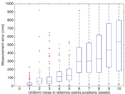
3.4 Computer simulation
To find out the dependency between the accuracy of coordinates of reference points in the image space and the measurement error of the MLZ algorithm a computer simulation was performed. For the simulation two points X0, X1 with random position were chosen. The distance from points to the origin of the object coordinate system was equal to 500 mm. All reference points configurations were used except those that result in the angle α
between line l and the optical axis of the camera smaller than 1 degree. The perspective center of the camera was located at the point � = 0 −1000 4000 ` (coordinates in mm). The parameters of the internal orientation of the camera were equal to the parameters of the camera of the Parrot AR.Drone 2.0 UAV.
The coordinates of the projection x0, y0 of points X0, X1 were found using collinearity equations. Uniform random error vector
Figure 7. Dependency between noise in the position of reference points and the measurement error of the MLZ algorithm
4. CONCLUSIONS
A new algorithm for estimation of an external orientation of a camera with known gravity vector was developed. The MLZ algorithm estimates the pose of a camera with respect to the given object coordinate system. To perform the estimation, the algorithm must be supplied with coordinates of two reference points in the object space, their projections in the image space and the direction of the gravity vector in the camera coordinate system.
The algorithm was implemented in a dedicated software for guidance of the Parrot AR.Drone 2.0 UAV. The evaluation of the algorithm was performed using computer simulation and flight experiments. The assessment of the algorithm proved that it is robust against errors in the image space coordinates of reference points up to 5 pixels. The analysis of the computer simulation has shown that the algorithm is robust against complex configurations of reference points.
The overall performance of the algorithm was accurate enough to perform a guided flight along the desired trajectory and a hovering flight with a quadcopter equipped with a frontal camera. The MLZ algorithm could also be used for a fast and robust estimation of the initial parameters of the external orientation for a bundle adjustment.
In further work it is planned to compare the algorithm performance with the performance of other modern P2P algorithms for cameras with known gravity vector direction such as methods proposed in (Kukelova et al., 2011), (D'Alfonso et al., 2014). To study the dependency between the field of view of the camera and the measurement error of the MLZ algorithm further experiments with different kinds of UAVs and different cameras are required.
ACKNOWLEDGEMENTS
The work was performed with the support by Grant of RF President for Leading Science schools of Russia (НШ -7247.2016.8) and by Grant 16-38-00940 мол_а of Russian Foundation for Basic Research (RFBR).
REFERENCES
Abidi, M.A., Chandra, T., 1995. A New Efficient and Direct Solution for Pose Estimation Using Quadrangular Targets: Algorithm and Evaluation. PAMI 17, pp. 534–538. doi:10.1109/34.391388.
Barnard, S.T., 1983. Interpreting perspective images. Artificial Intelligence 21, pp. 435–462. doi:10.1016/s0004-3702(83)80021-6.
Brown, D.C., 1966. Decentering distortion of lenses. Photometric Engineering. pp. 444-462. doi:10.1234/12345678.
D'Alfonso, L., Garone, E., Muraca, P., Pugliese, P., 2014. On the use of IMUs in the PnP problem. IEEEInternational Conference on Robotics and Automation (ICRA), pp. 914–919. doi:10.1109/ICRA.2014.6906963.
Fischler, M.A., Bolles, R.C., 1981. Random Sample Consensus: a Paradigm for Model Fitting with Applications to Image Analysis and Automated Cartography. CACM 24, pp. 381–395. doi:10.1145/358669.358692.
Förstner, W., 2010. Optimal vanishing point detection and rotation estimation of single images from a legoland scene. IAPRS, Vol. XXXVIII, Part 3A, pp. 157-162.
Kalantari, M., Jung, F., Paparoditis, N., 2008. Robust and automatic vanishing points detection with their uncertainties from a single uncalibrated image, by planes extraction on the unit sphere. The International Archives of the Photogrammetry, Remote Sensing and Spatial Information Sciences. Vol. XXXVII. Part B3a. Beijing 2008, pp. 203-207.
Knyaz V., 2010. Multi-media Projector – Single Camera Photogrammetric System For Fast 3D Reconstruction,” International Archives Photogramm. Remote Sens. Spatial Inf. Sci., Vol XXXVIII, Part 5, Commision V Symposium, pp. 343-348
Knyaz, V. A., 2015. Scalable photogrammetric motion capture system “Mosca”: development and application, Int. Arch. Photogramm. Remote Sens. Spatial Inf. Sci., XL-5/W6, pp. 43-49, doi:10.5194/isprsarchives-XL-5-W6-43-2015, 2015.
Kukelova, Z., Bujnak, M., Pajdla, T., 2011. Closed-Form Solutions to Minimal Absolute Pose Problems with Known Vertical Direction, in: Advances in Visual Computing, Lecture Notes in Computer Science. Springer Berlin Heidelberg, Berlin, Heidelberg, pp. 216–229. doi:10.1007/978-3-642-19309-5_17
Lepetit, V., Moreno-Noguer, F., Fua, P., 2008. EPnP: An Accurate O(n) Solution to the PnP Problem. Int J Comput Vis 81, pp. 155–166. doi:10.1007/s11263-008-0152-6
Lu, C.P., Hager, G.D., Mjolsness, E., 2000. Fast and Globally Convergent Pose Estimation from Video Images. PAMI 22, pp. 610–622. doi:10.1109/34.862199