A QUALITY EVALUATION OF SINGLE AND MULTIPLE CAMERA CALIBRATION
APPROACHES FOR AN INDOOR MULTI CAMERA TRACKING SYSTEM
Michele Adduci∗, Konstantinos Amplianitis∗and Ralf Reulke
Humboldt Universit¨at zu Berlin
Computer Science Department, Computer Vision Group Rudower Chaussee 25, 12489 Berlin, Germany
(michele.adduci, konstantinos.amplianitis, reulke)@informatik.hu-berlin.de
Commission V, WG V/1
KEY WORDS: Calibration, Single Camera Orientation, Multi Camera System, Bundle Block Adjustment, ICP, 3D human tracking
ABSTRACT:
Human detection and tracking has been a prominent research area for several scientists around the globe. State of the art algorithms have been implemented, refined and accelerated to significantly improve the detection rate and eliminate false positives. While 2D ap-proaches are well investigated, 3D human detection and tracking is still an unexplored research field. In both 2D/3D cases, introducing a multi camera system could vastly expand the accuracy and confidence of the tracking process. Within this work, a quality evaluation is performed on a multi RGB-D camera indoor tracking system for examining how camera calibration and pose can affect the quality of human tracks in the scene, independently from the detection and tracking approach used. After performing a calibration step on every Kinect sensor, state of the art single camera pose estimators were evaluated for checking how good the quality of the poses is estimated using planar objects such as an ordinate chessboard. With this information, a bundle block adjustment and ICP were performed for verifying the accuracy of the single pose estimators in a multi camera configuration system. Results have shown that single camera estimators provide high accuracy results of less than half a pixel forcing the bundle to converge after very few iterations. In relation to ICP, relative information between cloud pairs is more or less preserved giving a low score of fitting between concatenated pairs. Finally, sensor calibration proved to be an essential step for achieving maximum accuracy in the generated point clouds, and therefore in the accuracy of the produced 3D trajectories, from each sensor.
1 INTRODUCTION
In recent years, computer vision and machine learning groups started developing algorithms for detecting people in an orga-nized 3D point cloud which can be quite promising considering the metric informations that can be extracted from the detected people. In (Luber et al., 2011) a machine learning technique for detecting people in a point cloud using features trained in RGB and Depth images was developed. Another approach consists in an on-line boosted target models for detection and tracking (Spinello and Arras, 2011). These aforementioned techniques are applied using a single sensor; these approaches might suffer of typical 2D related problems which might occur in some scenar-ios, such as occlusions, fast illumination changes, natural or phys-ical scene constraints. Therefore it is important to investigate and research on techniques applied in a multi camera system, which can enhance the quality of informations retrieved from the envi-ronment and overcome the limitations of single camera systems. In this publication, we evaluate the calibration approaches for sin-gle and multiple camera, which are used in an indoor configura-tion for human detecconfigura-tion and tracking: knowing the absolute and relative position of the cameras, we are able to reconstruct a full 3D scene which can be analysed by tracking algorithms.
1.1 Related Work
In this work, we used a RGB-D sensor, a Microsoft Kinect, a low cost device which disrupted the computer vision’s world, en-abling a new series of studies, techniques and results. One of the most widely used approaches to calibrate a single camera, modeled as a pinhole camera model is the Brown model (Brown, 1971), and also the technique explained in (Zhang and Zhang,
∗These authors contributed equally to this work
1998) which estimate intrinsic camera parameters using a planar pattern. An analysis on the accuracy of data acquired using a Mi-crosoft Kinect was discussed extensively in (Khoshelham, 2011) and, for indoor mapping applications, in (Khoshelham and El-berink, 2012).
Since the RGB and the Infrared sensor must be co-registered, a cross calibration of both sensors must be performed. In (Almazan and Jones, 2013), they proposed an interesting approach to cali-brate Infrared and RGB sensors using normals on a plane is de-scribed.
In a multiple camera system, it is fundamental to know the po-sition of each camera respect to an object; some techniques con-cerning single camera pose estimation and solution to the Per-spective Three Point problem are discussed in (Gao et al., 2003) and (Lepetit et al., 2009). More refined approaches to compute intrinsic and extrinsic camera parameters, pose estimation and scene reconstructions are based on bundle adjustment, as reported in (Hartley and Zisserman, 2004) and (Luhmann, 2011). In gen-eral, the reconstructed 3D scene obtained from bundle adjustment or other techniques might require a better alignment and refine-ment: the best choice is to run the Iterative Closest Point (Besl and McKay, 1992) or one of its variants.
We mentioned above that human detection and tracking is an ac-tive topic: some interesting results are presented in (Luber et al., 2011) and (Spinello and Arras, 2011), which use a trained classi-fier based on RGB and Depth images, using Histograms of Ori-ented Gradients (HOG) and Histograms of OriOri-ented Depths based detectors.
2 THEORETICAL BACKGROUND
This section provides the reader with an overview of theoretical and mathematical disciplines intended for understanding the pro-posed approach.
2.1 Calibration
Calibration involves finding the parameters that will correct the position of an image point due to lens distortions. Within this work, calibration was done by combining the 10-parametric model introduced by (Brown, 1971) and the calibration approach in-troduced by (Zhang and Zhang, 1998). Employing the pinhole camera model, this is an ideal mathematical assumption for cam-eras that often deviate from the ideal perspective imaging model. Also, the pinhole model comes along with lens distortions param-eters which can compensate lens errors and give correct image points. Most important type of distortion is theradial distortion
which causes an inward or outward position of the image point from its ideal position and is expressed by:
∆xrad=x[k1r2+k2r4+k3r6+. . .]
∆yrad=y[k1r2+k2r4+k3r6+. . .]
(1)
wherex, yare the distorted image points,ris the euclidean dis-tance of every point in the image with respect to the principal point (also known asimage radius) andk1, . . . , kn are the ra-dial distortion coefficients used for modelling the rara-dial distortion curve. For most standard types of lenses, going further than the third order parameters could be neglected without any significant loss in the accuracy of the points.
Second form of distortion is thedecentering(or tangential) dis-tortion which is caused by physical elements in a lens not being perfectly aligned to the image plane and it’s existance is mostly due to manufacturing defects and can be compensated by the fol-lowing function:
∆xdec=p1(r2+ 2x2) + 2p2xy
∆ydec=p2(r2+ 2y2) + 2p1xy
(2)
wherep1,p2 are the decentering parameters. This lens
correc-tion part can give large values for low cost cameras (such as surveillance cameras) and smaller quantity distortion values for high quality lenses.
Finally, theaffinityandshearingparameters are used to describe deviations of the image coordinate system with respect to the non orthogonality and uniform scaling of the coordinate axes. This is mathematically expressed as:
∆xaf f=b1x+b1y
∆yaf f= 0
(3)
whereb1,b2express the affinity and shearing parameters
respec-tively. It is noteworthy that in most cameras used in close range application,b1andb2are set to zero.
Overall, these individual terms used to model the imaging errors could be summarized as follow:
∆x′= ∆x
rad+ ∆xdec+ ∆xaf f
∆y′= ∆y
rad+ ∆ydec+ ∆yaf f
(4)
For the calibration method introduced by (Zhang and Zhang, 1998), this is considered a well suited technique for finding the pose (position and rotation) of a camera by observing a planar pattern object (such as a chessboard) shown from at least two different
points of view. It is a close form solution, followed by a non-linear refinement based on a maximum likelihood criterion. For further technical information refer to (Zhang and Zhang, 1998).
2.2 Single camera pose estimation
Single camera pose estimation is a topic extensively investigated for many decades and it has several applications not only in com-puter vision but also in relevant fields such as robotics and aug-mented reality fields. Within this work, a quality evaluation on a recent iterative and non-iterative approach is made by checking the quality of the camera pose through its reprojection error. Sub-sequently, these pose parameters, together with the lens distortion coefficients computed in the calibration step for each camera, are given as initial values to a photogrammetric bundle block adjust-ment algorithm. Relative information between camera pairs is crucial for determining the initial rigid transformation guess re-quired as an input to the ICP algorithm.
As was previously mentioned, two different solutions to theP nP problem are evaluated. The first method is a non-iterative solu-tion proposed by (Lepetit et al., 2009), who tried to express the
n3D points as a weighted sum of four virtual control points. In this way, according to the author, time complexity (which is lin-early growing with n) is significantly reduced to a O(n) time. In the second approach, non linear Levenberg-Marquardt opti-mization algorithm was used for minimizing the sum of square distances between the observed points and calculated projected points. From the2D↔3Dcorrespondences, 3D points are con-sidered to be error-free while 2D points should be compensated for lens distortions. If that was not true, camera pose would be computed based on undistorted points which is not trivial.
2.3 Bundle Block Adjustment
Figure 1: The reprojection error
p= [P1, P2, . . . , Pn, X1, X2, . . . , Xm] (6)
wherePiis the3×4projection camera matrix overnnumber of cameras andXiare the 3D ground control points (chessboard points) which remain invariant throughout all the bundle process. An initial parameter vectorp0 and measurement vectorx
(ob-served image points) are required for finding a vector that best satisfies the functional relation, meaning finding the values of this vector that will locally minimize the objective function. As a stopping criterion, we define the error between the observed and calculated values, which has to be minimized (refer to relation 5). Using theGauss−N ewtonnon linear least square approach, the mathematical model is defined as follows:
JTJδP =−J εp (7)
whereJis the Jacobian matrix defined asJ = ∂ff((pp)),δpis the corrected measurement vector andǫpis the error between the ob-served and calculated measurement vectorsx−ˆx. For further reading refer to (Hartley and Zisserman, 2004) and (Luhmann, 2011).
2.4 Iterative Closest Point (ICP)
The Iterative Closest Point (ICP) algorithm is a widely used al-gorithm for registering two 3D datasets. Within the alal-gorithm, one point cloud acts as the reference cloud (also known as tar-get), while the other one, known as source, is transformed to best match the reference. That involves an iteration process in which the source cloud would undergo a rigid transformation (that im-plies translation and rotation) for minimizing the distance to the reference point cloud. In mathematical notation, ICP could be given in the form of a pseudo code as seen in algorithm 1. For further details of the algorithm refer to (Besl and McKay, 1992). Using the same notation as in the pseudo algorithm for the source dataset(P) and target dataset(M), the rigid relative transforma-tionRM P given as an initial guess for the ICP is defined as:
RP M=RMTRP
TP M=RMT(TP −RM)
(8)
whereRP,RMexpress the rotation matrices that rotate the source and target clouds to the world system andTP,TMexpress the po-sition of the clouds within the world system.
Algorithm 1Iterative Closest Point (ICP) algorithm
Require: P(source) andM(target) datasets Ensure: Transformation(R′,t′), Errorε
1: R′←I,t′←0,ε← ∞
2: while(ε > threshold)do
3: Y ← {m∈ M |p∈ P:m=cp(p)}
4: (R,t, ε)←min R,t
np
P k=1
|yk−Rpk−t|2
5: P ←R· P+t
6: R′←R·R′ 7: t′←R·t′+t
8: end while
2.5 People Detection and Tracking
Detecting people in a point cloud is a current research topic for many scientists. Within this work, detection of people is based on previous work introduced in (Amplianitis et al., 2014), where cur-rent foreground is extracted by detecting the spatial differences between the computed OcTree of the static background and the OcTree of the current cloud.
In the tracking part, Kalman filter was used to predict the next tar-get location of the person. Initialization of the tracking was done by extracting the convex hull of the body silhouette and comput-ing the mean from it. Every person was detected and tracked independently by every sensor.
3 EXPERIMENTAL RESULTS
The experimental part is divided into three sections: First section is a description of the room used for testing and evaluating the detection and tracking algorithm. Second section provides results coming from the internal calibration process of each Kinect sen-sor. In the third section, an evaluation of the bundle adjustment accuracy and the ICP algorithm are given based on the initial camera pose parameters computed by the algorithms explained in section 2.2. Finally in the fourth section, we demonstrate some tracking results of moving people in the scene and discuss the ac-curacies.
For chariness within this section, additional tables and graphs have been appended in an Appendix section.
3.1 Camera configuration and hardware
Our experimental setup consists of four RGB-D Microsoft Kinect sensors mounted on a aluminium construction as depicted in fig-ure 2. The space within the aluminium construction has dimen-sions of approximately4.5×2.2×2.3depth, width and height re-spectively. Data acquisition was done from all cameras in parallel with an acquisition rate of≈19fps. One of the main drawbacks of using multiple structured light sensors is the drastic reduction of the quality of the depth images due to the intersection of their near-infrared light in space. Therefore, all sensors where oriented looking towards the center of the scene and the amount of over-lapping was restricted only in the lower part of the field of view (FOV).
The depth is produced by projecting a known pattern onto the scene by the infrared emitter and then infer depth from the de-formation of that pattern recorded by the infrared image. The resolution of the RGB and depth images is640×480pixels and so the generated point cloud has an organized form of 307200 points. Best working limit without introducing artifacts is within the range of 1.2 and 3.5 meters.
Concerning hardware performance, a computer with an Intel Core i7-3770 processor, 16GB RAM and a Samsung 840 Pro SSD was used. Although good hardware is essential for these kinds of ap-plications, real time detection and tracking would require extra hardware performance and software optimization.
Figure 2: Aluminium construction with mounted Kinects sensors
3.2 Calibration
There are several libraries (eg. OpenNI, FreeKinect) which pro-vide out-of-the-box calibration parameters of the Kinect sensor. Nevertheless, for achieving maximum possible accuracy of the generated point clouds (implying better 3D tracking results), a more precise calibration is required. Main advantage of the Kinect sensor is that it uses low distortion lenses with faintly apparent displacement errors around the corners/edges of the images. The calibration process was conducted in the following manner: as a 3D object, a well defined chessboard pattern was used with a chessboard size of2cmand inner dimensions of5×7rows and columns respectively. Since infrared and RGB sensors can-not work simultaneously, they were switched on and off continu-ously (a switch lasts 0.5 seconds), in order to acquire roughly the same chessboard data, from different perspectives. Detection and acquisition of chessboard points was done in a live mode using OpenCV’s chessboard corner detector, which also provides sub-pixel accuracy. To avoid any disturbances of the speckles com-ing from the infrared emitter in the infrared camera, the emitter was covered with tape and a external light was used for detect-ing the chessboard corners. A total amount of 100 images was acquired and splitted using a random selection algorithm in 10 different sets of 24 images each, in which the calibration was performed independently from other sets. Applying (Zhang and Zhang, 1998) algorithm stated in section 2.1, internal calibration results are given in tables 3 and 4 of Appendix A. The overall RMS for the infrared and RGB camera respectively for each cam-era is given in table 1. As was expected, the RMS is within the range of almost a quarter of a pixel for every sensor significantly outperforming in quality the RMS default results provided by the default Kinect parameters (0.34px for IR and 0.53px for RGB
camera). Figures 6 and 7 from Appendix A show the radial sym-metric curve of the infrared and RGB lenses of every Kinect sen-sor expressed by the principal point. It is clear that the radial distortion almost follows a constant zero effect for most of the distances and starts effecting the points’ displacement only to-wards the edges of the image (less of half a pixel in the extreme regions in both infrared and rgb sensor). Moreover, the decen-tering distortions parameters provided by table 4 in Appendix A have very small values clearly proving the quality and stability of both infrared and RGB lenses.
Sensor Type A B C D
IR 0.1711 0.2171 0.2079 0.3357 RGB 0.2284 0.2409 0.2162 0.2157
Table 1: Calibration RMS error for IR and RGB sensor (in pixels)
3.3 Single camera orientation and bundle adjustment Solving a bundle block adjustment system requires good initial approximated values for internal and external parameters of all sensors. As was mentioned in section 3.1, all four RGB-D sensors are mounted in a way that would be quite complicated for a per-son to empirically provide sufficient initial guess. One solution to the problem was to use the well knownDirect Linear Transfor-mation (DLT)algorithm but for planar objects such as the chess-board, DLT would fail due to its coplanarity constrain. Therefore, approaches such asP nP−LMandEP nPthat are designed to retrieve the pose of a camera from planar objects where consid-ered (refer to section 2.2).
Figure 3: Optimized reprojected image points
ID A B C D
PnP - LM 0.240 0.247 0.255 0.231 EPnP 0.463 0.432 0.389 0.372
Table 2: Kinects reprojection error for initial pose estimation (in pixels)
Full ground control points were generated from the chessboard with their Z value set to zero.
Figure 4: Final result of ICP fusion. Left figures shows two people standing and iteracting whears in the right figure two are sitting and chatting
distribution information and introduce several geometrical con-strains. Acquiring the pattern from all four sensors simultane-ously and running the algorithms discussed in section 2.2 the re-sultant reprojection errors are given in table 2 which can also be seen in figure 3.
The generation of point clouds is performed using Kinects’ depth and RGB image: the depth information is used to produce the 3D points, which are then textured using RGB information. Mathematically this is expressed by finding the rotation and trans-lation parameters (3D rigid transformation) between the two cam-era systems which can be computed through a classical stereo calibration procedure. Knowing the focal length, principal point and radial distortion parameters, every 3D point (expressed now in the RGB camera system) can be projected on the RGB im-age, interpolate the color and assign it to the point (Khoshelham, 2011). Therefore, it is clear that the rest of the working pipeline will be based on point clouds orientated with respect to the RGB camera system rather than the infrared.
Considering all exterior and interior parameters as unknown for each sensor, a bundle block adjustment was applied for refining these parameters so that the condition 5 is met. Setting a con-vergence condition of0.0001mas a minimum distance between observed and calculated points, bothP nP −LM andEP nP converged after 3 iterations and returned aσo of 0.00029and 0.00032respectively. It is clear that both methods provide sim-ilar pose parameters and therefore explains the minimal correc-tions bundle adjustment did on the initial values. Results of point clouds translated and oriented with respect to the world chess-board system are given in figure 4. Left figure shows the complete fused cloud together with the presence of two people interacting with each other. As can be seen, both human are represented as a solid body. Equivalent results are also given by the right figure with two people sitting on a chair.
Given as initial guess the relative transformation between two pair-wise clouds, ABand CD, based on equation 8, ICP was performed only once for the first frames of a scene and remained fixed for the rest. The number of iterations given as a converging conditions were 500, with an epsilon of1×10−8and maximum
correspondences’ distance of5cm. For the first pair,AB, the score of convergence was0.017m, whereas for the second pair, CD, the convergence was0.048m. In both cases, the fusion was done quite fast and with a very good error fit.
3.4 Human detection and tracking
As was stated in section 2.5, moving objects are extracted from all sensors independently and in a parallel process. Knowing the refine relationship between the sensor pairs A−B and C− D(coming from ICP), all foreground points extracted indepen-dently from each sensor are now transformed in the same coordi-nate system. As a result, when a person is currently in the scene, all points corresponding to him will move in the same direction. Pay notice that random error and point density play a significant role in the accuracy of the foreground. The further away a person is from a sensor, the larger the random error is generated from that sensor. Also, the density of a point is inversely proportional to the square distance from the sensor, which also explains the reduction of density resolution in larger depths. Thus, people be-ing closer to a sensor will contain points from that sensor with a higher density and accuracy and vice versa.
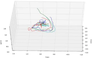
Figure 5: Trajectories of a person as produced by each sensor
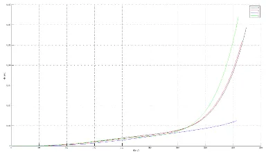
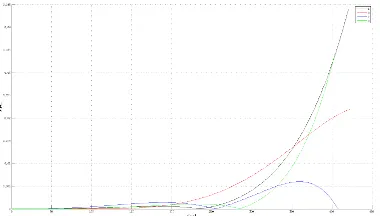
trajectory coordinate elements into three separate planes, an anal-ysis of each dimension is accomplished individually. Figures 8, 9 and 10 from Appendix B show the amount of variation for each coordinate component independently with the larger offsets vis-ible in the Z axis. That clearly shows that the fluctuation in the size of the convex hull mostly effects the Z direction and less the X and Y.
4 CONCLUSIONS
We performed a processing chain for demonstrating how calibra-tion, bundle adjustment and ICP can affect a multiple RGB-D human detection and tracking system. Pre-calibration of every Kinect sensor is an essential step for rectifying the RGB and IR images and producing high quality point clouds. Although the correction of infrared and RGB images is mostly in the extrema regions, this could significantly affect the position of a moving object in the scene, depending on the distance of the object from each sensor. Planar single pose camera estimators have shown that although they have small orientation differences, they don’t lack of accuracy and that was immediately proven by perform-ing a bundle block adjustment. Given as initial values the results coming from the single camera pose estimators and setting all in-ternal and exin-ternal parameters as unknowns to the bundle (except ground control points) the algorithm would converge after very few iterations achieving aσo of less than amm. Giving as ini-tial guess a 3D rigid transformation to ICP for every pair of point clouds, the fitting score for both pairs was withincmaccuracy, clearly proving the necessity of all aforementioned procedures. In the detection and tracking part, generated trajectories of mov-ing people were shifted one another due to the accuracy of the foreground and therefore the tracked center of gravity.
5 DISCUSSIONS
Presented work could serve well as a solid foundation of evaluat-ing multi RGB-D camera systems. Human detection and trackevaluat-ing in a point cloud is still an unexplored area with not much work introduced by the research community. Therefore, improving our current implementation and refining foreground masks could sig-nificantly improve the accuracy of the tracks. Optimal goal in-volves having a unique trajectory for every person in the scene produced by the confidence of the intermediate tracks generated from each sensor.
Time performance is also a very crucial factor for our algorithm. Using GPU programming could significantly improve our algo-rithmic workflow and bring it closer to a more real time appli-cation. On the other hand, RT applications would require hav-ing one computer per sensor, due to the amount of computational power needed to manage all devices simultaneously.
REFERENCES
Almazan, E. J. and Jones, G. A., 2013. Tracking people across multiple non-overlapping rgb-d sensors. In: The IEEE Confer-ence on Computer Vision and Pattern Recognition (CVPR) Work-shops.
Amplianitis, K., Adduci, M. and Reulke, R., 2014. Calibration of a multiple stereo and rgb-d camera system for 3d human tracking. ISPRS - International Archives of the Photogrammetry, Remote Sensing and Spatial Information Sciences XL-3/W1, pp. 7–14.
Besl, P. J. and McKay, N. D., 1992. A method for registration of 3-d shapes. IEEE Trans. Pattern Anal. Mach. Intell. 14(2), pp. 239–256.
Brown, D. C., 1971. Close-range camera calibration. Photogram-metric Engineering 37(8), pp. 855–866.
Gao, X.-S., Hou, X.-R., Tang, J. and Cheng, H.-F., 2003. Com-plete solution classification for the perspective-three-point prob-lem. IEEE Trans. Pattern Anal. Mach. Intell. 25(8), pp. 930–943.
Hartley, R. I. and Zisserman, A., 2004. Multiple View Geometry in Computer Vision. Second edn, Cambridge University Press, ISBN: 0521540518.
Khoshelham, K., 2011. Accuracy analysis of kinect depth data. ISPRS - International Archives of the Photogrammetry, Remote Sensing and Spatial Information Sciences XXXVIII-5/W12, pp. 133–138.
Khoshelham, K. and Elberink, S. O., 2012. Accuracy and reso-lution of kinect depth data for indoor mapping applications. Sen-sors 12(2), pp. 1437–1454.
Lepetit, V., F.Moreno-Noguer and P.Fua, 2009. Epnp: An ac-curate o(n) solution to the pnp problem. International Journal Computer Vision.
Luber, M., Spinello, L. and Arras, K. O., 2011. People tracking in rgb-d data with on-line boosted target models. In: Proc. of The International Conference on Intelligent Robots and Systems (IROS).
Luhmann, T.; Robson, S. S. K. H. I., 2011. Close Range Pho-togrammetry: Principles, Methods and Applications. Second edn, Whittles Publishing of Caithness, Caithness, Scotland, UK.
Spinello, L. and Arras, K. O., 2011. People detection in rgb-d data. In: Proc. of The International Conference on Intelligent Robots and Systems (IROS).
Zhang, Z. and Zhang, Z., 1998. A flexible new technique for camera calibration. IEEE Transactions on Pattern Analysis and Machine Intelligence 22, pp. 1330–1334.
APPENDIX
Appendix A: Calibration results
Figure 7: Radial symmetric distortion curves for all RGB sensors
ID cx cy xo yo
RGB
A 569.833 569.117 335.038 259.227 B 569.220 569.198 323.839 260.600 C 586.786 585.971 327.520 240.808 D 591.379 591.084 330.742 241.404
Infrared
A 511.908 510.640 330.890 259.780 B 497.488 497.568 326.354 267.325 C 516.212 516.059 324.874 246.470 D 521.307 520.709 323.213 242.130
Table 3: Infrared and RGB camera internal parameters (in pixels)
ID k1 k2 p1 p2 k3
Infrared
A -0.1648 0.7673 0.0069 0.0064 -1.3135 B -0.1480 0.6950 0.0079 0.0017 -1.2501 C -0.0992 0.2648 0.0022 -0.0036 -0.2833 D -0.1933 1.1570 0.0002 0.0039 -2.4079
RGB
A 0.0288 -0.1249 0.0070 0.0056 -0.0506 B 0.0093 -0.1718 0.0124 0.0048 0.1517 C 0.0803 -0.4595 0.0072 -0.0008 0.5304 D 0.0187 0.0259 -0.0009 0.003 -0.2990
Table 4: Infrared and RGB camera lens distortion parameters (in pixels)
ID Tx Ty Tz Rx Rx Rx
A -2.16 0.01 0.78 0.9370 0.2804 -0.3862 B -2.68 0.41 -0.63 0.8422 0.0489 0.1004 C -1.84 -0.73 -0.09 0.536 -2.6761 -0.2824 D -2.01 0.11 -0.19 -0.1178 0.4829 0.2939
Table 5: Translation (cm) and rotation (deg) parameters between RGB and IR camera
Appendix B: Detection and tracking
Figure 8: Variation of the trajectories along the X axis
Figure 9: Variation of the trajectories along the Y axis