PHOTOGRAMMETRIC EXPLOITATION OF HDR IMAGES FOR CULTURAL
HERITAGE DOCUMENTATION
A. Ntregkaa, A. Georgopoulosa, M. Santana Quinterob
aLaboratory of Photogrammetry, School of Rural & Surveying Eng.,
National Technical University of Athens
bDepartment of Civil and Environmental Engineering and the Azrieli School of Architecture,
Carleton University of Canada
KEY WORDS: High Dynamic Range Images, Calibration, Orthophotography, Cultural Heritage Documentation
ABSTRACT:
Basic goal of this project is to investigate and therefore highlight the usefulness of High Dynamic Range Images for photogrammetric applications in the field of Cultural Heritage Documentation. Scenes with High Dynamic range - difference between the brightest and the darkest parts - is impossible to be recorded without loss of details and texture in dark areas (due to underexposure) and in bright areas (due to overexposure) because of digital sensor's limitation in high dynamic range recording. In digital recording, the most recent and effective solution is High Dynamic Range Images (HDRI). These images are created by merging multiple images of the same scene, each of which has been taken with different shutter speed and thus providing a better range of images with different exposures. An HDR image alone is overcoming the loss of information caused by unfavorable lighting conditions. In photogrammetric applications, images have to be of high quality and represent faithfully the scene they depict. For applications of Cultural Heritage Documentation, where during image acquisition lighting conditions might be difficult, HDR technology can positively contribute to the acquisition of images of better quality and, consequently, to the creation of orthophotos with no radiometric problems. In this paper, a detailed reference to HDRI technology is made and also the geometric reliability and photogrammetric applicability of HDR images is examined and confirmed. In addition, an example of photogrammetric application in Cultural Heritage Documentation is presented and evaluated.
1. INTRODUCTION
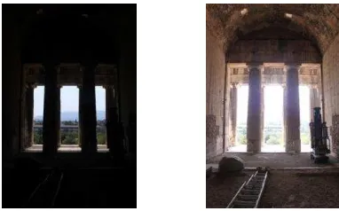
In photogrammetric applications of Cultural Heritage documentation and especially as far as photogrammetric deliverables such as orthophotographs is concerned, the need for qualitative imaging and reliable geometric information is very high and demanding. The metric images used should be as faithful visual representations as possible of the scene they depict. Cultural Heritage documentation professionals usually are faced with difficult lighting conditions, such as underexposed interiors in high contrast with natural light coming from the outside (Figure 1). This is usually attributed to the high dynamic range of the scene.
Figure 1: Example of adverse lighting conditions
In order to overcome these problems and improve the lighting conditions for suitable image acquisition many techniques have been employed, like use of special filters, artificial lighting and other expensive photographic studio equipment. However, as far as monuments are concerned, there are severe limitations in the use of some of such techniques. These limitations include available time and cost, the character of the monument that very
2. HIGH DYNAMIC RANGE IMAGES measured in Exposure Values (EV), or equivalently f-stops, bits or contrast ratio. Exposure Value is the combination of shutter speed and aperture that allows a certain amount of reflected or emitted light to reach the digital sensor and be recorded. In terms of EV the human eye, after pupil's adjustment, is able to perceive a range of 24EV which is more than enough for common, real-world scenes of 10-14EV. Unlike the abilities of the human eye, the digital camera, due to the limited capacity of sensor's photosites, can only record 5-9EV (32:1 – 512:1), while a standard computer monitor is able to display contrast ratio of 500:1 and a typical photographic printer can print images of no more than 300:1 contrast ratio (Nightingale, 2012). In other words, scenes with high dynamic range, i.e. high differences between dark and bright areas, are recorded as images of low dynamic range where dark parts of the scene are underexposed and thus displayed with too dark pixels and bright parts are overexposed and thus displayed with too bright pixels. When the camera is set to auto exposure (0EV), the light meter measures the reflected light and dedicated algorithms, based on the scene's lighting pattern, calculate the suitable combination of shutter speed and aperture (www.cambridgeincolour.com). Usually, scenes of high dynamic range are not recorded satisfactorily. Even when the exposure is adjusted manually it is likely that over- and underexposed parts will be present. This loss of texture and detail reduces dramatically the quality and truthfulness of the final image since light is the significant factor of the quality of an image.
2.2 High Dynamic Range Imaging
High Dynamic Range Imaging (HDRI) in image processing and photography is the method of creation of images that contain a wider dynamic range than the one a single digital image can record. This is possible by merging multiple images of the same scene which have different exposures. This special image acquisition typically requires extended storage memory due to the number of images taken and, preferably, a camera with Auto Bracketing Exposure and Aperture Priority functions, which allow the shooting of a bracketed sequence of exposures with different shutter speed and the selection of exposure spacing (Nightingale, 2012). Furthermore, any means that can be used to minimize movement between images, such as a tripod or a cable release, are necessary in order to ensure that every image depicts exactly the same scene. These multiple exposure images are digitally combined and processed in specialized HDR software or typical image processing software with HDR functions, in order to create the final image of high dynamic range. Those software are also capable to reduce or even eliminate common problems of HDR images such as presence of noise, ghosting effects caused by moving objects in the scene during the taking sequence, halo effect etc.
2.4 Radiance Map
The multiple exposure images are merged and create a 32-bit depth HDR image format also known as radiance map. For achieving radiance mapping, i.e. radiance values attribution to every pixel, the work of Debevec & Malik is usually preferred,
whose algorithm takes into account the reciprocity of values and by using differently exposed photographs recovers the response function of the imaging process, up to a scale factor. After the response curve's recovery and the conversion of pixel values to relative radiance values, all available exposures are used in
The HDR format (.hdr, .pic) contains a short ASCII header and the size and orientation of the image are defined by a resolution string that follows the header. For pixel data two types are used, a 4-byte RGBE encoding and a CIE variant, XYZE (Reinhard et al., 2010). Owing to the fact that 32-bit image files contain a very wide tonal range (4.3×10⁹ tones) which, as explained above cannot be displayed or printed by conventional media, the HDR images are initially displayed according to the monitor's capability in dynamic range display. In other words, one cannot see the whole dynamic range of the image and thus HDR Image of 16-bit or 8-bit depth. Therefore, the term HDR image of the final deliverable does not correspond to reality since the final HDR image is a tone mapped LDR image. In this paper, from this point on and for simplicity, the term HDR image will be used instead of tone mapped LDR image and the term radiance map will be used instead of HDR image. Tone mapping is carried out by a wide selection of operators that are chosen basically according to the result desired. There are two categories of tone mapping operators: global and local. Global operators map each pixel according to its intensity and global image characteristics and values. Consequently, every pixel is mapped in the same way. A tonal curve is a global operator. On the other hand, local operators are more complex and use the values of the surrounding pixels to map a single one. As a result, pixels on bright areas are mapped differently from those on dark areas. This procedure creates final images with greater contrast and thus more detailed (Pratyush, 2009). Generally speaking, global operators create more realistic images while local operators create more artistic images, but this is not always the case since their efficiency depends on the application.
different exposures result in different parts of the scenes recorded sufficiently every time. For instance, the outside area
is recorded very well, with high contrast and details, in low exposures while it is overexposed and thus significantly less detailed in high exposures. On the contrary, in high exposures the inside area has sufficient light and thus satisfactory amount of information. This example is indicative of the limitation in high dynamic range recording from conventional media and with conventional methods. The multiple exposure images of the sequence of the example were inserted in the Photomatix Pro software and two HDR images were created (Figure 3).
Figure 3: HDR images of the sequence of Figure 2, tone mapped with global (left) and local (right) operator
The first HDR image was created with a global operator. The result is quite satisfactory comparing to the original ones, because the light is more balanced all over the image. The other HDR image was created with local tone mapping operator. In this case, the results are even more satisfactory. The contrast is higher, providing the viewer with more details of both dark and bright parts of the scene. Details of the reflectance on the floor, of the wooden roof, of the outside area and of the walls are remarkably highlighted. Especially, the amount of information from walls and the marble floor is dramatically improved compared to the single photos and to the global tone mapped HDR image. This example successfully illustrates the beneficial use of HDR images which contain the whole dynamic range of the scene depicted. In addition, since the scene is typical for a monument, it also highlights the capability of HDR images to provide the user, in Cultural Heritage documentation applications, with images containing high amount of information throughout the scene. This is possible even when the lighting conditions during photo shooting are difficult and the presence of visitors prohibitive for extensive use of technical solutions that improve the shooting.
3. GEOMETRIC PROPERTIES OF HDR IMAGES
3.1 Need for Geometric Investigation
In order for HDR images to be used in rigorous photogrammetric applications, it is necessary to assess their geometric reliability. This investigation will ascertain whether the HDR image creation inserts geometric errors and changes the central projection of the initial images, i.e. their interior orientation parameters. Basic errors that change the geometry of an image are (Samara, 2004):
• Radial lens distortion: caused due to the difference in direction between the incoming and the outgoing beam from the internal perspective center of the lens and causes distortion of points radially from the principal point
• Non symmetrical lens distortion: caused by the not perfect alignment of lens elements and is very small comparing to radial distortion
• Different x- and y- axis scale: caused usually by the non quadratic shape of the pixels
• Non-verticality of axes
For this investigation, the interior orientation of both HDR and normal images were determined through a standard calibration procedure and they were compared. In order for the HDR images to be considered geometrically reliable, the results of their calibration have to be stable and close to the ones of the initial images.
3.2 Calibration of images
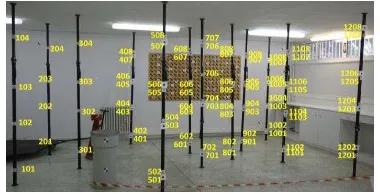
For this task, the Calibration Test Field in the Metrology Center of the School of Rural and Surveying Engineering of National Technical University of Athens (Figure 4) was used. It contains a large number of points with known geodetic coordinates with an accuracy of 0.1mm. A standard self calibration procedure was used (Samara 2004).
Figure 4: The Calibration Test Field of the Metrology Center of the School of Rural and Surveying Engineering of NTUA
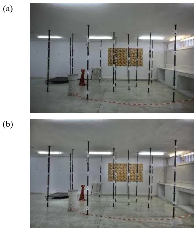
The images of the field were taken with two lenses of focal length 24mm and 50mm respectively. All shootings and procedures were made for both lenses. From every taking position, 2-3 bracketed exposure sequences of images were taken and HDR images was created with Photomatix Pro software (Figure 5) using local tone mapping operator to increase local contrast in order to enable the measurements on the images. Image coordinates of the test field points on 22 images (11 normal and 11 HDR) were measured with the use of AutoCAD software using the add-on tool Toporest of Fotopo Ltd. The self calibration was performed using the Calibration_CCD software (Samara, 2004) where .txt files of geodetic and image coordinates were imported as input data. Figure 2: Bracketed exposure sequence of images from
For every image the calibration software created an output file with the following values:
• xo,yo (in mm): principal point's coordinates • c (in mm): principal distance
• K1, K2: radial distortion coefficients
• P1, P2: non symmetrical distortion coefficients
• Skewness (in grad): deviation from verticality of y-axis from the x-axis
• Scale: scale factor of y-axis
All calculations resulted with an a posteriori error of less than 0.3 pixel; consequently they were all included in the final results and conclusions.
(a)
(b)
Figure 5: (a) Photo of 0EV of the Control Field taken with 24mm lens and (b) corresponding HDR image
3.3 Calibration Results
In Tables 1 and 2, the average values of all calibrations for both normal and HDR images are shown. The differences calculated for both lenses for xo, yo, c, K1, K2, skewness and scale factor values are very small. Hence it can be considered that those elements between normal and HDR images do not change significantly. Significant differences are present for non
symmetrical distortion factors P1 and P2. However, non symmetrical distortion has a negligible effect on image geometry. In conclusion, and after the detailed investigation described, it is safe to assume that interior geometry between initial photos of the bracketed exposure sequence and the final HDR image is practically the same. Thus, HDR images may safely be considered reliable for use in photogrammetric applications.
50mm LENS
calibration results
normal images ΗDR images
differences
xo(mm) 17.7912 17.7875 0.0037
yo(mm) 11.7956 11.8549 -0.0593
c(mm) 51.8443 51.8258 0.0185
K1 -2.78521 * 10-9 -2.71133 * 10-9 -0.07388 * 10-16
K2 0.90193 * 10-16 0.80451 * 10-16 0.09743 * 10-16
P1 0.07990 * 10-8 0.30396 * 10-8 -0.22405 * 10-8
P2 -1.75661 * 10-8 -6.30311 * 10-8 4.54651 * 10-8
skew 0.00153 0.00034 0.00119
scale 0.99992 1.00010 -0.00018
Table 2: Calibration results and comparison between normal and HDR images with 50mm focal length lens
4. PHOTOGRAMMETRIC IMPLEMENTATION
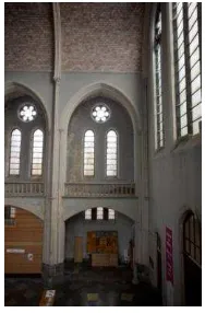
Using HDR imagery orthophotographs were created for the documentation of a Cultural Heritage Monument, namely the north gallery of Saint Francis Xavier Church in Anderlecht, Brussels. It is a neo-gothic church, designed and constructed in 1911 by the architect Leopold Pepermans. Its inauguration took place in 1915. After a long time of gradual decline, in 2008 Brussels Main Regional Authority with an ordinance demanded to protect the Saint Francis Xavier Church as a monument and safeguarding zone (Vandesande et al., 2011). The orthophotomosaics depicted the elevation of part of the north gallery as seen from the interior of the church. This work was part of a greater documentation and restoration study, carried out within the framework of a postgraduate project of RLICC of the Catholic University of Leuven.
4.1 Creation of the Orthophotographs
Taking into account the available equipment and the object itself, for the documentation of part of the gallery, it was decided that one stereo pair would be enough. The 24mm camera lens with a full frame (36x24mm2) Canon MIII camera was used with a 70% overlap, i.e. 2m base for a 15m mean distance from the object. This resulted to an image scale of 1:600 scale and 5mm ground resolution, which were adequate for a 1:50 scale orthophotograph. The images were taken from the south gallery.
Lighting conditions in the church were adverse and demanding. The only source of light was natural light coming in from the windows, while the rest of the church was relatively dark. In other words, the dynamic range and especially in the galleries was very high. The character of the place (a church where masses take place regularly) and its degraded state and pathology were prohibitive for use of photo studio equipment or other time consuming and expensive methods to improve lighting conditions. For this reason, HDR image acquisition was 24mm LENS
calibration results
normal images ΗDR images
differences
xo(mm) 17.9735 17.9638 0.0097
yo(mm) 11.7767 11.7859 -0.0092
c(mm) 24.5794 24.5791 0.0003
K1 -5.57297 * 10-9 -5.48897 * 10-9 -0.08400 * 10-9
K2 4.01247 * 10 -16 3.9612247*10-16 0.05124 * 10-16
P1 0.11668 * 10 -8 -4.76920 * 10-8 4.88588 * 10-8
P2 -0.47498 * 10-8 -2.60734 * 10-8 2.11324 * 10-8
skew -0.00337 0.00252 -0.00589
scale 0.99984 0.99995 -0.00011
preferred in order not only to create an HDR image but also to investigate the possibility of use of different than 0EV exposure. The camera had all the necessary functions for automatic bracketed exposure and also a tripod and a remote release were available. Finally, two bracketed exposure sequences were taken from -3EV to 3EV with 1.5EV spacing. This means 5 images per taking position (Figure 6).
Figure 6: Bracketed exposure sequence of the scene from -3EV to -3EV with 1.5EV spacing
The problem of the dynamic range recording is obvious in this case. The pathology of the windows is only depicted well in low exposure images. On the other hand, in high exposures some parts of the gallery are depicted well, while others like the wall on the gallery are overexposed losing texture and detail. For this problem, HDR imaging were considered the ideal solution.
For the creation of the HDR images (Figure 7) was performed using the open source HDR software Luminance. The tone mapping was done with a local operator.
Figure 7: The HDR image created by the sequence of Figure 6
One can easily note the superiority in information of the HDR image compared to each of the primal ones. The light is balanced throughout the image and there is sufficient
information not only for windows and parts around them but also for parts with less light.
For the creation of a Digital Surface Model (DSM) of the gallery laser scanning took place. The scanning was done with Scan Station 2 of Leica Geosystems and the processing of the point cloud was made with Cyclone software of the same company. Afterwards, the point cloud was processed in Geomagic Studio software of Geomagic and the final DSM was created. From that DSM geodetic coordinates of GCP’s were extracted to be used for the photogrammetric procedures. The orientations and the creation of orthophotographs were carried out with Image Master software by Topcon. A significantly useful conclusion from this part of the project is that the photogrammetric procedure itself and especially the measuring of points on the images remarkably easier when HDR images were used due to their high contrast. Orientations of normal images was twice as time consuming as orientations of HDR images. The deliverables were two orthophotographs which then were merged into a single orthophotomosaic within AutoCAD software by Autodesk. This procedure took place for normal and HDR images respectively. The orthophotomosaics for both types of images were made from the exact same parts of the orthophotographs in order to be compared.
4.2 Comparison and Evaluation
The final orthophotomosaics are those shown in the Figure 8 and after the orthophotographs' merging there was no further digital processing in order for them to be compared objectively. Hatched parts indicate insufficient laser scanning data.
What is observed at first glance on the orthophotomosaics, is that the normal one indispensably needs digital, radiometric post processing in order that the separate orthophotographs are not distinguishable. On the contrary, the HDR orthoimage needs no further processing because the separate images cannot be distinguished. This uniformity in light and lack of shadows and hidden or overexposed parts in HDR image is the result of the recording of the whole dynamic range of the scene whereas in normal images only a narrow part of the dynamic range of the scene was recorded. In addition, due to different taking positions and different angle of light, the low dynamic range recorded was different for each image. This ended up in very different primal images and thus an orthophotomosaic which needs more processing.
(a) (b)
Figure 8: Orthophotomosaics made by (a) normal and (b) HDR images
As far as the information itself is concerned, HDR image has significantly much more information than the normal and the light is balanced all over the image. For instance, one can observe better not only decorative details but also elements of the church pathology like cracks, extensive existence of humidity on the walls and pathology of the windows. This information in the normal image is lost due to underexposure of the wall and the overexposure of the windows. Also, even in the lower right vault where the light is not enough, still in HDR image there is sufficient light and thus information. What is more, linear elements on the HDR image are more distinct than in normal image making the HDR image more reliable for measuring. What should be mentioned is that normal orthophotomosaic can have a better result with effective digital processing. However, this result would be limited by the low amount of information recorded due to camera's limitations in high dynamic range recording as has explained already. Taking into account the geometric reliability of HDR images one can safely come to the conclusion that for this application HDR images turned out to have higher quality than normal images. In other words, with their superiority in information they can be more effective in Cultural Heritage applications like restoration or risk mapping. Assuming that there was no ability for intervention on the lighting conditions of the light of the scene, HDRI was the best solution since it increased the high dynamic range and as a result, improved the quality of the information recorded.
5. CONCLUDING REMARKS
HDR imaging is a relatively new method in digital imaging but has gained the interest of experts due to the solution it provides for the problem of dynamic range recording which has been a demand from the beginning of photography. Taking into account all previously mentioned, one can safely come up to some useful conclusions about HDR images generally and their use in photogrammetry in particular. Apart from the fact that HDR images are indeed able to solve the dynamic range recording problem and improve the quality of digital images as already thoroughly described, HDR images have even more advantages. In photogrammetry and after the confirmation of their geometric reliability, the increase of the dynamic range recorded not only provides the user with more information, but also facilitates the photogrammetric procedure due to the high contrast that highlights points, detail and pre-marked ones, necessary for measuring. In addition, the use of HDR images waives the necessity for digital radiometric post processing of orthophotomosaics. This is an important advantage since digital post processing is often a significantly time consuming work. One more positive aspect of HDR imaging is that it does not exclude the conventional digital photographic methods, since bracketed exposure sequences can include the default exposure image of 0EV. Thus, there is always the choice of rejecting an HDR image if the result is not the desired one and of using a conventional LDR image. One more remarkable advantage of HDRI is that there is wide choice of HDRI software, including commercial ones, free and open source. These software are simple and user friendly and provide the user with a variety of tone mapping methods and image processing functions. In this way, it is possible for the user to create a final image very close to his desire. On the other hand, HDRI is a time consuming
procedure, still less than digital post processing of LDR images, which doesn't always have satisfactory results. The demand for special equipment is not a significant disadvantage because usually, in most professional photo shootings, SLR cameras and tripods are used. Maybe, the most important demand of this method is the strong need for extended memory since for every scene the images taken are more than one. As far as the final quality of the deliverables and problems such as halo effect and ghosting effect are concerned, HDR software can improve the result or even completely eliminate these phenomena. It would be of great importance to note that HDR images are affected by the printing limitations, as the HDR image printed has narrower dynamic range from the one displayed on the monitor. However, even this low dynamic range, is more balanced throughout the image and thus the information is more faithful to the scene. To summarize, it is concluded that HDRI is a method which can be significantly useful in many applications. Images which are faithful representatives of the original scenes, the easy image acquisition, the relatively non demanding equipment, the variety of HDR software and the continuous technological improvement of the method, all make High Dynamic Range Imaging method one of the most effective and useful in digital imaging and especially when Cultural Heritage is documented.
6. REFERENCES
Adams A., 1981. The negative, ISBN 0-8212-1131-5, Little Brown and Company, New York, pp. 272.
Banterle F., Artusi A., Debattista K., Chalmers A., 2011, “Advanced High Dynamic Range Imaging”, ISBN 978-1-56881-719-4, A.K. Peters Inc. Natick, Mass. pp 260.
Debevec P. E., Malik J., “Recovering High Dynamic Range Radiance Maps from Photographs”, SIGGRAPH '97, Proceedingd of the 24th annual conference on Computer graphics and interactive techniques, pages 369-378
Nightingale D., 2012, “Practical HDR”, Lewes, pp.205 Pratyush P., 2009, “High Dynamic Range Imaging”, National Institute of Technology Rourkela, pp.246
Reinhard E., Ward G., Pattanaik S., Debevec P., Heidrich W., Myszkowski K., 2010, “High Dynamic Range Imaging - Acquisition, Display and Image Based Lighting”, Burlington