70 Laboratory Experiments Physics PHYWE Systeme GmbH &Co. KG · D - 37070 Göttingen
Principle:
An ultrasonic wave is subjected to surface reflection from a metal plate. The reflected wave superimposes on the incident wave, coincident in phase and amplitude, to form a standing wave. The intensity of this wave along the direction of propaga-tion is measured using a movable ul-trasonic receiver.
The change in the sound pressure intensity in the direction of propagation as a function of the distance.
Tasks:
1. Determine the intensity of a standing ultrasonic wave by mov-ing an ultrasonic receiver along the direction of propagation. 2. Plot a graph of the measured
val-ues as a function of the distance. 3. Determine the wavelength of the
ultrasonic wave.
Ultrasonic unit 13900.00 1
Power supply f. ultrasonic unit, 5 VDC, 12 W 13900.99 1
Ultrasonic transmitter on stem 13901.00 1
Ultrasonic receiver on stem 13902.00 1
Digital multimeter 07134.00 1
Optical profile-bench, l= 60 cm 08283.00 1 Base f. opt. profile-bench, adjust. 08284.00 2 Slide mount f. opt. profile-bench, h= 80 mm 08286.02 1 Slide mount f. opt. profile-bench, h= 30 mm 08286.01 2
Sliding device, horizontal 08713.00 1
Swinging arm 08256.00 1
Screen metal, 30⫻30 cm 08062.00 1
Connecting cord, l= 50 cm, red 07361.01 1 Connecting cord, l= 50 cm, blue 07361.04 1
What you need:
Complete Equipment Set, Manual on CD-ROM included
Stationary ultrasonic waves, determination
of wavelength
P2151300
What you can learn about …
Longitudinal waves Superposition of waves Reflection of longitudinal
waves
Related topics
Longitudinal waves, superposition of waves, reflection of lon-gitudinal waves, stationary lonlon-gitudinal waves.
Principle
An ultrasonic wave is subjected to surface reflection from a metal plate. The reflected wave superimposes on the incident wave, coincident in phase and amplitude, to form a standing wave. The intensity of this wave along the direction of propa-gation is measured using a movable ultrasonic receiver.
Equipment
Ultrasonic unit 13900.00 1
Power supply f. ultrasonic unit, 5 VDC, 12 W 13900.99 1
Ultrasonic transmitter on stem 13901.00 1
Ultrasonic receiver on stem 13902.00 1
Digital multimeter 07134.00 1
Optical profile-bench, l = 60 cm 08283.00 1
Base f. opt. profile-bench, adjust. 08284.00 2
Slide mount f. opt. profile-bench, h= 80 mm 08286.02 1 Slide mount f. opt. profile-bench, h= 30 mm 08286.01 2
Sliding device, horizontal 08713.00 1
Swinging arm 08256.00 1
Screen metal, 30x30 cm 08062.00 1
Connecting cord, l= 50 cm, red 07361.01 1
Connecting cord, l= 50 cm, blue 07361.04 1
Task
1. Determine the intensity of a standing ultrasonic wave by moving an ultrasonic receiver along the direction of propa-gation.
2. Plot a graph of the measured values as a function of the distance.
3. Determine the wavelength of the ultrasonic wave
Set-up and procedure
Set up the experiment as shown in Fig. 1, referring to Fig. 2 for a clear illustration of the distances between components.
Fig.1: Experimental set-up
Fig.2: Diagram showing the positions of the components (t = transmitter, r = receiver, sc = screen)
21513-00 PHYWE series of publications • Laboratory Experiments • Physics • © PHYWE SYSTEME GMBH & Co. KG • D-37070 Göttingen
2
Mount the ultrasonic transmitter and the ultrasonic receiver at the same height and with their longitudinal axes vertical and parallel to each other. Position the transmitter in alignment with the optical bench and pointing vertically to the reflector screen. Position the receiver parallel to the reflector screen and at a distance of approx. 5 cm from it.
The distance between transmitter and reflector screen should be d= (25-30) cm.
Connect the transmitter to the TR1 diode socket of the ultra-sonic unit and operate it in continuous mode “Con“. Connect the receiver to the left BNC socket (prior to the amplifier). Connect the signal received to the analog output of the digital multimeter to have it displayed subsequent to amplification and rectification. To ensure proportionality between the input signal and the analog output signal, avoid operating the amplifier in the saturation range. Should such a case occur and the “OVL“ diode light up, reduce either the transmitter amplitude or the input amplification. To start with, for control and avoidance of overloading, use the sliding device to bring the screen to the area of the 1st maximum of the measurement curve.
Following this, use the sliding device to move the receiver towards the transmitter in 0.2 mm steps, measuring the appropriate receiver voltage Uat each step.
Note:
As a rule, it is not possible to completely avoid interference to the measurement field by reflected sound. To keep such inter-ference as small as possible, do not carry out the experiment in narrow rooms. Do not set the experiment up in the immedi-ate vicinity of reflecting surfaces (walls, cupboards etc.). Positioning the ultrasonic unit and the multimeter behind the reflector screen at some distance from the measurement area is recommended. In addition, the person carrying out the experiment should not stand too close to the measurement area.
Theory and evaluation
When an ultrasonic wave hits a hard wall, then it is reflected without loss. The incident and reflected waves have the same frequency and amplitude. Superpositioning of the incident sound pressure wave p1 and the reflected sound pressure
wave p2 results in the formation of a standing wave of p =
p1+p2(superpositioning principle).
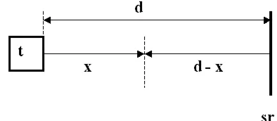
In order to not make the mathematical treatment unnecessar-ily difficult, plane waves are assumed as a first approximation, i.e. the real case of spherical waves whose amplitude de-creases with the reciprocal value of the way is ignored. If dis the distance between transmitter and receiver, then for the behaviour in space and time of the alternating sound pres-sures of incident wave p1(x,t) and reflected wave p2(x,t) (see
Fig. 2) we have:
(1)
The result of the addition of the two waves is a standing wave p(x,t):
(2)
See the Appendix for a detailed calculation of p(x,t).
Standing wave p(x,t) is periodic in space and time. The posi-tion dependent part of the alternating sound pressure is always a maximum when the cos function becomes 1, in other words, when the argument is 0, p, 2p, 3p,..….This is always the case, however, when x= d- 1/2nl(n = 0, 1,2,3...). The
alternating sound pressure amplitude will be in particular max-imal at the reflector (x= d, n = 0), i.e. there is always an oscil-lation or movement node here but a pressure anti-node. It is also clear that the distances between standing wave pressure maxima is l/2.
At the maxima, the pressure amplitude of the standing wave is double that of a single wave. When the argument is a cos function of zero, then the alternating sound pressure ampli-tude is also zero, i.e. there are oscillation anti-nodes or pres-sure nodes at these positions when x= d- 1/4(2n+1)l (n = 0,
1,2,3...).
The distances between neighbouring pressure anti-nodes or pressure nodes amount to ∆x= 1/2l.
Fig. 4 shows an example of a measurement. The values of the distances (d-x) of the pressure anti-nodes and pressure nodes
⫽2p0 · sin2pa
Fig. 3: Back and forth path of the ultrasonic wave (t = transmitter, sr = screen)
of the standing wave from the reflector screen are given in the Table.
Table: The distances of the pressure anti-nodes and pressure nodes from the reflector screen.
The wavelength of the standing wave lst obtained from the mean of the ∆(d-x) values of neighbouring pressure anti-nodes and pressure nodes is lst= (4.27±0.15) mm. From the rela-tionship 2lst = l, we then obtain l = (8.54±0.3) mm for the wavelength of the ultrasonic wave.
In comparison to this, calculating from known values trans-mitter emission frequency f = 40 kHz, and c = f·l (c = 343.4 ms-1 at T = 20°C), a wavelength of l = 8.58 mm
8.6 mm is found.
As a sound pressure is always existent in experimental room because of the operation of the transmitter in it, the measure-ment area is also always influenced by this to a certain extent. This is the reason for the different intensities of the individual pressure nodes and pressure anti-nodes, and also why the amplitudes of the pressure nodes never return to zero.
Appendix:
(3)
(Circular frequency v= 2p/Tand wave number k= 2p/l)
Rearranging equation (3) using addition theory:
21513-00 PHYWE series of publications • Laboratory Experiments • Physics • © PHYWE SYSTEME GMBH & Co. KG • D-37070 Göttingen