1
DDA2322 Hidraul (Hydraulics)
Bab 6 – Pam Empar (Displacement Pumps)
6.1 Pengenalan
Sistem-sistem aliran (flow systems) kadang-kadang mengguna alat mekanikal untuk:
Menambahkan tenaga kepada bendalir (add energy to the fluid)
Mengeluarkan tenaga daripada bendalir (remove energy from the fluid)
Alat yang menambahkan tenaga mengalirkan bendalir untuk menaikkan halaju atau tekanan:
Pam-pam – bendalir dialirkan oleh alat; tenaga dari luar sistem diperlukan (e.g., tenaga elektrik, motor petrol)
Alat yang mengeluarkan tenaga digerakkan oleh bendalir dan menghasilkan tenaga untuk tindakan yang lain:
Motor bendalir (fluid motors)
Turbin (turbine)
Akuator putaran (rotary actuators)
Akuator linear (linear actuators)
Biasanya pam-pam diguna dalam kerja juruteraan, contoh: 1) Sistem sumber air (water-supply systems)
2) Sistem pembetungan (sewerage and sewage disposal systems) 3) Sistem menyejukkan air (water-cooling systems)
4) Sistem penulenan air (water-purification systems)
5) Mengeluarkan air dari tempat pembinaan atau perlombongan (dewatering at construction or mining sites)
Keperluan untuk mengepam air:
1) Mengepam air mentah dari sumber ke tempat penulenan (To pump raw water from a source to a purification plant – raw water pumping)
2) Mengepam air dari bawah ke tangki yang atas (To pump water to an elevated tank or high-level reservoir – pure water pumping)
3) Mengepam air di dalam sistem pengagihan (To pump water directly into the main distribution pipes)
4) Mengepam air dari sumber air bumi ke permukaan tanah (To pump well water into the overhead tanks in one-two stages [i.e., first stage: well to ground level; second stage: ground level to elevated tanks])
5) Mengepam air untuk menaikkan tekanan air di dalam sistem pengagihan (To pump for improving pressure [boosting pressure] in the distribution system at high points)
6.2 Jenis-jenis Pam
Pumps are classified according to the way in which they draw water for discharge. The three categories are:
1) Pam empar (displacement pumps) 2) Pam centrifugal
3) Pam airlift
Pam Empar (Displacement Pumps)
2
Mengguna prinsip/asas positive displacement = tanpa kebocoran; isipadu air di dalam pam tetap; tidak bergantung pada turus (head) di dalam pam (isipadu yang masuk = isipadu yang keluar)
Piston atau plunger menarik air masuk (intake stroke) kemudian menolak air keluar (discharge stroke)
Pam Empar Membalas
Sesuai untuk turus (head) yang tinggi dan beban yang naik-turun
Keefisienan (efficiency) ~90% asalkan head > 30m
Pam Empar Berputar
Sesuai untuk air yang berada pasir atau debu atau batu halus (grit)
Kadar air keluar seragam
Haluan Aliran
Haluan axial
Haluan radial
Haluan campur (mixed)
Asas Bagi Prestasi Pam (3 ciri):
1) Muatan atau keupayaan (capacity) dan kadar keluar 2) Tekanan atau turus (head)
3) Keperluan tenaga (power requirements)
Components of a Centrifugal Pump (See diagrams)
Main components:
Impeller –“flings” (melemparkan) water, does not “cup” the water Cut-water –“pinches” water flow at volute casing
Volute – casing in which the impeller rotates
Suction nozzle – inflow port
Discharge nozzle – outflow port
90° angle = radial flow
5 6.3 Fundamentals of Pump Performance
Pump Characteristics
Head Developed (Fig. 15.5)
H = Hd– Hs =
d = discharge side (outflow)
s = suction side (inflow)
Pump Power Produced (Kuasa Yang Keluar)
Po= ρ g Q H
Typically, we know output power (Po) and need to calculate the input power (Pi):
Pi = =
6 Contoh 6.1
Calculate the specific speed of a pump that is operated by a 1800-rpm electric motor and delivers 0.0031 m3/s against a dynamic head of 13.7-m.
Q = 0.0031 m3/s
Using the same values, but with the other equation gives:
Ns =
upon the English units equation)
Take a look at Fig. 15.11
Using the first number (0.266) along the top x-axis and the second number (727) along the bottom x-axis, we see that the efficiency of this particular pump is ~83% for this particular set of operating characteristics.
6.4 Affinity Laws
i) A pump discharges 0.030 m3/s at a rotation of 3000 rpm. Slowing the rotation to 1500 rpm produces what discharge?
7
iii) If the power in condition 1 was 20-hp (@3000 rpm), how many hp would be produced in condition 2 (@1500 rpm)?
P2 =
=
=
2.5 hpCase 2: Changing the impeller diameter (D) in the pump but keeping the speed (N) constant
Contoh 6.2
A pump delivers 0.032 m3/s at a head of 21.3-m when run at a speed of 3600 rpm. Determine the change in operating characteristics if the pump impeller is changed in diameter from 150-mm to 100-150-mm.
Similarity laws allow us to predict the performance of a prototype (contoh, ulang) pump from testing a scaled model.
Q = KQ N D3 KQ = pekali kadaralir
H = KH N2 D2 KH = pekali turus
P = KP N3 D5 KP = pekali kuasa masukan
yang mana:
N = specific speed (no units) D = impeller diameter (m) Q = kadar alir (m3/s) H = head (m)
10 6.6 Pump Characteristic Curve (PCC)
Pumps each have their own „performance characteristic curve‟ which is typically supplied by
the OEM (original equipment manufacturer).
E.g., Fig 15-7
Q plotted vs. Head (H) and Efficiency (η)
BEP = Best Efficiency Point
The point on the H vs Q curve where efficiency is at a maximum
The normal range of operating efficiency for a pump is 60-80%.
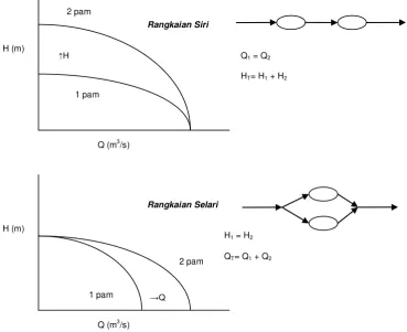
6.7 Pumps Operating in Series and Parallel
Figure 15.16 (d) dan (e)
Pada stesen-stesen mengepam (pumping stations), keperluan Q dan H naik turun bersama masa (fluctuate with time)
Mungkin satu pam tidak cukup
Beberapa pam akan digunakan untuk mengawal semua keperluan
Pilihan: menaiki P (tekanan) ataupun menaiki Q (kadaralir)
Rangkaian siri (series) digunakan untuk menaiki P
Rangkaian selari (parallel) digunakan untuk menaiki Q
Amalannya, pam-pam yang berada ciri-ciri yang sama (saiz dan prestasi) digunakan untuk mendapat efisiensi yang tinggi
11
Dua pam yang seiras (identical characteristics) dalam rangkaian siri berada Q lebih sama dengan satu pam sendiri tetapi pada turus tekanan yang dua kaliganda (2× the the head)
Dua pam yang seiras dalam rangkaian selari berada H lebih sama dengan satu pam sendiri tetapi pada kadaralir yang dua kaliganda (2× the discharge)
12 6.8 Rangkaian Paip (Pipe Networks)
6.8.1 Paip Sendiri (Single Pipe)
Rumusan yang penting:
V =
V = halaju bendalir di dalam paip (m/s) Q = kadaralir (m3/s)
υ = viskositi kinematik (m2
/s)
Kaedah untuk mendapat nilai bagi ʄ dan hf
Lihat E 0-2 Moody‟s Diagram
1) Untuk aliran lamina (laminar flow): ʄ =
2) Untuk aliran turbulen dalam paip yang licin (smooth-pipe): hf = (0.1580)(υ0.25)
bagi julat 3000 ≤ Re ≤ 105
3) Untuk aliran turbulen dalam paip yang kasar penuh (fully-rough):
ʄ = ʄmin =
yang mana ialah kasaran relatif (relative roughness)
atau hf =
6.8.2 Kehilangan Turus Paip Sendiri (Single Pipe Head Losses)
Geseran (friction) – hf kehilangan turus yang paling besar
Kehilangan kecil (minor losses)
Kehilangan masuk (entrance losses)
13
Luahan ke dalam bendalir yang bergerak (discharge into moving fluid)
Penguncupan (contractions)
Pengembangan (expansions)
Kehilangan pada kelengkapan paip (pipe fittings)
Kehilangan pada lengkungan dan liku (bends and elbows)
hL = hf + Σh′
hL ialah jumlah kehilangan turus (total head loss)
Kalau paip sangat panjang dengan sedikit kelengkapan, lengkungan, penguncupan dan
lain-lain, kemudian Σh′ ≈ 0 dan
hL = hf
6.9 Ciri-ciri Sistem dan Lengkung Ciri-ciri Sistem (System Characteristics and System Characteristics Curve, SCC)
Rumusan Tenaga Am (General Energy Equation)
HL = kehilangan turus (head losses); kehilangan tenaga (energy losses)
HA = tenaga mekanikal yang dimasuki ke sistem oleh pam
HR = tenaga mekanikal yang dikeluar dari sistem oleh turbin, mesin, dll
E1 + HA– HR– HL = E2 Pengabadian Tenaga (Conservation of Energy)
E = + Z +
Tenaga Dimiliki oleh Air
+ Z1 +
+
HA– HR– HL=
+ Z2 +Gunakan untuk menjawab soalan
Tutorial 6.3, 6.4, 6.5
E1
E2
15
6.10 Sifat Operasi Pump (Operating Point of a Pump)
The manner is which a pump operates depends upon both the performance characteristics of the pump (PCC: Curve A below) and the pipeline or system characteristics (or requirements, SCC: Curve B below).
The intersection of the two curves (PCC and SCC) indicated the operating point of the pump. The head that the pump must develop is equal to the static lift plus the total head loss (HL) in
the pipe system.
Tutorial 6.6, 6.7, 6.8
H (m)
Q (m3/s)
A, PCC
B, SCC
Operating Point, H vs Q
ΔZ = static lift