Water Level Measurement Altitude Trainer Integrated With
Human Machine Interface
Ade Gafar Abdullah*, Agung Pramudiantoro Putra
Department Pendidikan Tekhnik Elektro, Universitas Pendidikan Indonesia Jl.Dr. Setiabudhi No 229, Bandung, Indonesia
* Correspondence: [email protected]
A B S T R A C T S A R T I C L E I N F O
This research aims to design a trainer simulator wake height of the water level measurement using microcontroller arduino mega integrated with Human Machine Interface (HMI). This tool is designed to describe a working system of water level elevation measurements as a learning medium HMI. By using a microcontroller arduino mega, all processes in both input and output can be integrated to the HMI using a 7-inch LCD screen.
© 2017 Tim Pengembang Journal UPI
Article History:
Received 03 Jul 2017 Revised 18 Aug 2017 Accepted 29 Aug 2017 Available online 01 Sep 2017
____________________ Keywords:
Human Machine Interface, Microcontroller,
Water Level, Simulator, Trainer.
Indonesian Journal of Science & Technology
DOI: http://dx.doi.org/10.17509/ijost.v2i2
p- ISSN 2528-1410 e- ISSN 2527-8045
1. INTRODUCTION
Requirement in automation control systems is increasing and growing, where the role of humans is still very dominating industrial control systems. For example, in response to the magnitude of the process, the system is measured by use of the control system. Indeed, the control system can be obtained by only using settings panel and relevant switchs. Because factors affect the efficiency and productivity of itself (Gumelar et al., 2013), one of them the use of the microcontroller and Human Machine Interface (HMI). Microcontroller with low power consumption can serve as a liaison hardware with software in order to control the logic input and output (Sahin & Olmez, 2010; Evans et al., 2016), while the HMI has functions as the interface where the user interacts with the system on the instrument directly that are realtime (Das et al., 2013). HMI is also used to maintain operational safety. The HMI should be designed from the accurate process control system. Thus, this will not cause an error when the operator makes the value of the state of the process at work.
Arduino Mega microcontroller is used as a controller to regulate the process control system, which processes the data output and input will be displayed on the LCD screen as the HMI. In this HMI, instructional media tools made using the water level elevation measurement plan. The use Arduino as a medium of learning tool for the development of automation system is aimed at training students in microcontrollers, programming C / C ++,
embedded systems, industrial
communications system to the object-oriented C #, .Net, Java and Python (Currás-francos et al., 2014).
LCD screens are used to make the display interface on the HMI. To manufacture GUI for HMI on the LCD screen
Nextion, editor software required. In making the GUI, display on HMI designer must understand the function of the system is a tool in advance, in order to neutralize an error in the reading system by the operator. In making the design of the HMI should be analyzed first, so we know what needs to be used in the tool.
Application of the microcontroller on Automation and SCADA systems have been conducted in 2012 in order to build a project based learning (PBL) in undergraduate program control and automation engineering from the Federal University of Ouro Preto. Since these implementations cause a lot of interest from students to work and to development in the works of their final project. In the next period, the microcontroller used in Automation or SCADA systems in practice at the classroom.
This paper discusses the design trainer water level elevation measurement system with a microcontroller using arduino mega, this tool was made on a plan Automation system with water level elevation measurements are monitored in realtime by using an LCD screen as HMI. With the creation of the media or the tool, in order to help students in learning HMI, system must have the knowledge directly in the manufacture of programming the HMI interface. The purpose of the creation of this tool is to facilitate the use of tool lab facilities Automation engineering industry in the world (Thomas et al., 2004).
2. MATERIAL AND METHODS
The next step is water that will be heated by using heater. Water temperature will be read using a temperature sensor DS1B820. When the temperature is already in a state with a certain temperature value, the mixer will rotate to stir the water and then the process is complete. In order for this tool works automatically, the entire system at the height of the water level tool is integrated with a microcontroller and HMI devices. The first step in the design is the design and identification of equipment and materials to be used. (Bilad, 2016; Mojaveri & Moghimi, 2017; Pebriyanti et al., 2016)
Table 1 shows lists of the equipment and materials used. Research was conducted at the Laboratory of Electronics Industry, Universitas Pendidikan Indonesia. This study focused on the design, the assembly and the testing. The first phase of the design stage, which is conducted by trainers design process using computer software such as Solidwork 2014, Adobe Photoshop and other similar software, then assembling trainers using appropriate tools and materials planning. The second stage is the stage of designing HMI software use Nextion Editor. The third stage is the stage of program design using C Arduino software IDE (Integrated Development Environment) Arduino v.1.6.12. The fourth stage is to conduct performance testing includes testing tools connection with the Arduino mega trainer integrated with the control system HMI on the LCD screen.
3. RESULTS AND DISCUSSION 3.1Design tool
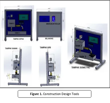
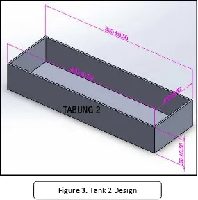
This simulator is designed with a practical concept for use with mobile concept and portable. Thus, users do not have difficulty at the time of the simulation lab practices indoors or elsewhere. Construction design tool can be seen in cuboid with reservoir water volume of 1.152 L which has a size of a mechanic with a length of 120 mm, width of 80 mm and height of 120 mm. Construction of designed tank 1 can be seen in Figure 2. Tank 2 has a function as a water reservoir, where the water before heading to the water tank 1 starting position is located on the tank 2. This tank is rectangular with reservoir water volume of 1.5 L that has a mechanical size with a length of 300 mm, width 100 mm, and height 50 mm. Construction design of tank 2 can be seen in Figure 3.
No Equipments Specification Quantitiy
1 Arduino Microcontrollers Arduino Mega 50 Pin I/O 1
2 LCD Screens HMI 7-inch Enchaded Model 1
3 Sensor Ultrasonic Proximity Sensor 3 – 300cm 1
4 Water Pump Q = 1200 l/h 1
5 Acrilyc 1 m², Heavy 5 mm 1
6 Frame Aluminium Lengthy 2 m 1
DOI: http://dx.doi.org/10.17509/ijost.v2i2
p- ISSN 2528-1410 e- ISSN 2527-8045
Figure 1. Construction Design Tools
This plant adapts to arduino mega microcontroller which has 54 I / O, 16 analog inputs and 4 UARTs (hardwere serial port). Arduino Mega is quite simple and very suitable to be used as a training device is simple in learning Human Machine Interface. Working voltage of 220 V is used for AC source and 12 V 1 A for dc voltage source. This plant designed to train students in programming capability on the basis of input and output of the microcontroller. In this trainer can train logic skills in processing input and output data to be displayed on an LCD screen as Human Machine Interface.
The working principle of measurement of plant height of the water level has centered on an LCD screen measuring 7 inches either the input or output process. To raise the water from the tank 2 into the tank 1 first step to do is turn on the water pump first and then the valve 1 opens automatically or manually to open the waterway leading to the tank 1, the speed of the water flow can be determined by flow sensors, with this we can know the speed of
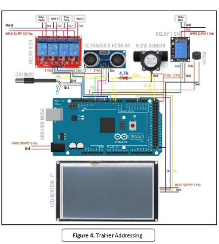
the water flowing in the process. When water is in the tank 1 altitude can be measured using ultrasonic sensors so that the water level can be known, and then after the water has to be at a certain height then the next process is carried out is heating the water using the water heater, the temperature of the water can be determined by reading from the sensor DS18B20 temperature. Furthermore, the water will be mixed using a mixer after the the plant simulator is divided into two parts, the first component of the two component inputs and outputs. Each component has an addressing used in the programming language C arduino.
DOI: http://dx.doi.org/10.17509/ijost.v2i2
p- ISSN 2528-1410 e- ISSN 2527-8045
Input Addressing Output Addressing
Ultrasonic Sensor Trig Pin 9
Echo Pin 8
Relay 1 (Water Heater) Pin 4
Water Temperature Sensor DS18B20
Pin 3 Relay 2 (Valve 1) Pin 5
Flow Meter Sensor Pin 2 Relay 3 (Water Pump) Pin 6
Relay 4 (Valve 2) Pin 7 Relay 5 (Motor Mixer) Pin 10
Buzzer Pin 11
LCD Screen Serial 1 (data
communication)
Tabel 1. Addressing I / O On Trainer
Addressing used affect the wiring on the microcontroller arduino mega trainer simulator mainly on the level gauge water
level. Below in Figure 4 shows the wiring in the draft trainer.
Figure 5. First Appearance.
DOI: http://dx.doi.org/10.17509/ijost.v2i2
p- ISSN 2528-1410 e- ISSN 2527-8045
3.2. HMI design
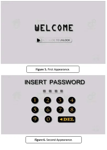
In designing HMI for automation, system is the elevation measurement of water level. The first step is to design the appearance of the HMI in the form of a picture or symbol - a common symbol that is easily understood by the operator, the display HMI must be made in accordance with the needs of the appliance and is shown for ease of operator in understand and be able to operate it with ease. HMI display design made in this trainer are 6 parts of the display. First, as shown in Figure 5, the start before going is to see the password entry on the HMI system.
For a second display, there is a display the password input that has been programmed on the HMI system before entering the third is to see home display. Detailed the second display can be seen in
Figure 6.
After entering the password correctly, the next step is to get into the third display which display the home. this is a display function as a display center where all functions of the system is located. The system can be seen in Figure 7.
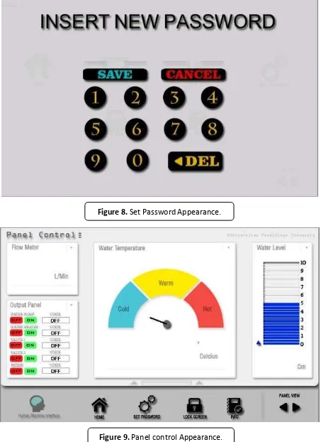
Figure 8. Set Password Appearance.
DOI: http://dx.doi.org/10.17509/ijost.v2i2
p- ISSN 2528-1410 e- ISSN 2527-8045
The third view has a display with various systems with different functions, including home display, control panel, set a password, lock screen and display information. To view home and to see the display on the lock screen, the display shows the first-time view with a set password display. menu in setting the new password is shown. Display set password can be seen in Figure 8.
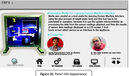
On the control panel display, the function of the display or menu is as the main view of the work process tool system either input or output work processes. Control panel display can be seen in Figure 9.
In this view, all systems work in process inputs and outputs. The device is
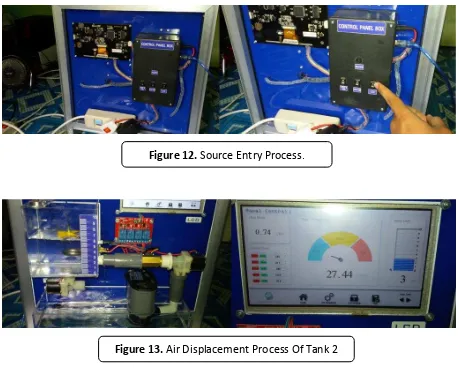
operated by the operator. The image push button on/off function of the work process can input for activating a relay on a microcontroller arduino mega, while the display meter temperature, water level, and text writing. The value is shown in reading the existing sensor the tool as the output process in the HMI system. Later, the info view serves as a menu to display information about the tool. To see the info, Figure 10 is shown.
All views and menus on the LCD screen as HMI created using software Nextion Editor. This software can create HMI into a beautiful and user frendly display.
3.3. Program design
Arduino programming language in use is a C language Arduino. Arduino programming language in a very easy to use for instructional media microcontroller systems. The first step to do is by knowing programming in any port that is used by the
microcontroller on each input and output, such sensor installed on arduino mega, then start typing the program and command in the software application IDE (Integrated Development Environment) in Arduino v.1.6.12. Sample programming can be seen in Figure 11.
DOI: http://dx.doi.org/10.17509/ijost.v2i2
p- ISSN 2528-1410 e- ISSN 2527-8045
3.4. Testing tools
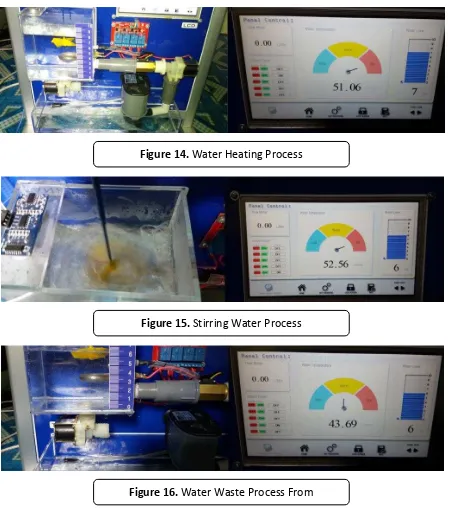
On testing tool first step to do is connect the appliance to 220 V AC voltage source. Then, we can turn on the switch sources for microcontroller system, AC 220 V and supply LCD on the device, this process can be seen in Figure 12.
Then, we go to the main menu on the HMI control panel. In the control panel, we activate pump water first and then turn the valve 1 and then see the water running from the tank 2 toward the tank 1. This process can be seen in Figure 13.
When the water has to be at a certain height and then the next step is to activate
the water heater by turning on the water heater on the LCD screen, which is on the water temperature. The temperature can be seen directly on the display HMI, which is shown in Figure 14.
When the water is heated, the next step is turning mixer to mix the water by pressing the push button on the mixer. Then, the motor will start. The process is completed already in the tank 1. The detailed process can be seen in Figure 15.
Then turn on the second valve to lower the water that is in the tank 1 toward the tank 2, this process can be seen in Figure 16.
Figure 12. Source Entry Process.
4. CONCLUSION
The process of the tool has been completed then the water in the tank 1 back to the starting position By using a microcontroller arduino mega on this trainer, work processes input and output goes well, arduino mega highly suitable for use as training students in learning microcontroller with integrated HMI, as it is considered quite capable in running order preprogrammed. Human Machine Interface with a clear view in realtime
very useful for operators in the reading of all the processes performed on the appliance.
With a budget that is more efficient, can make a useful learning media in industrial automation systems.which is located on the tank 2.
5. ACKNOWLEDGEMENTS
Authors thank to Universitas Pendidikan Indonesia.
Figure 14. Water Heating Process
Figure 15. Stirring Water Process
DOI: http://dx.doi.org/10.17509/ijost.v2i2
p- ISSN 2528-1410 e- ISSN 2527-8045
6. AUTHORS’ NOTE
The author(s) declare(s) that there is no conflict of interest regarding the publication
of this article. Authors confirmed that the data and the paper are free of plagiarism.
7. REFERENCES
Bilad, M. R. (2016). Module-Scale Simulation of Forward Osmosis Module-Part A: Plate-and-Frame. Indonesian journal of science and technology, 1(2), 249-261.
Curras-Francos, M. D. C., Diz-Bugarin, J., Garcia-Vila, J. R., & Orte-Caballero, A. (2014). Cooperative development of an arduino-compatible building automation system for the practical teaching of electronics. Tecnologias del Aprendizaje, IEEE Revista Iberoamericana de, 9(3), 91-97.
Das, R., Dutta, S., Sarkar, A., & Samanta, K. (2013). Automation of Tank Level Using Plc and Establishment of Hmi by Scada. IOSR Journal of Electrical and Electronics Engineering (IOSR-JEEE), 7(2), 61-67.
Evans, A., Ortega, C. U., Marinis, K., Costenaro, E., Laroussi, H., Obbe, K. V., & Ferlet-Cavrois, V. (2017). Heavy-Ion Micro Beam and Simulation Study of a Flash-Based FPGA Microcontroller Implementation. IEEE Transactions on Nuclear Science, 64(1), 504-511.
Gumelar, R., Abdullah, A.G. & Somantri, M., 2013. Simulator Sistem Pencampur Warna Otomatis Berbasis PLC Terintegrasi Human Machine Interface. Electrans, 12(2), 115– 126.
Mojaveri, H. S., & Moghimi, V. (2017). Determination of Economic Order Quantity in a fuzzy EOQ Model using of GMIR Deffuzification. Indonesian Journal of Science and Technology, 2(1), 76-80.
Pebriyanti, G., Zhu, R., & Rehiara, A. B. (2016). Sludge Dewatering Process Control Using Principal Component Analysis (PCA) and Partial Least Square (PLS). Indonesian Journal of Science and Technology, 1(1), 61-73.
Sahin, S., Olmez, M., & Isler, Y. (2010). Microcontroller-based experimental setup and experiments for SCADA education. IEEE Transactions on Education, 53(3), 437-444. Thomas, M. S., Kumar, P., & Chandna, V. K. (2004). Design, development, and