Based on Haptics
February 2014
A thesis submitted in partial fulfilment of the requirements for the degree of
Doctor of Philosophy in Engineering
Keio University
Graduate School of Science and Technology
School of Integrated Design Engineering
This dissertation is the summary of my research from April 2009 to February 2014 as a member of Ohnishi laboratory in Keio University. I have been a member of Ohnishi laboratory, Faculty of Science and Technology, Keio University, since April 2009. My research activity started when I enrolled in Professor Ohnishi’s research group five years ago. It has never been completed without time and helps of many people.
First of all, I would like to express my sincere gratitude to my supervisor Professor Dr. Kouhei Ohnishi in Keio University. His dedicated teaching has grown me and has provided numberless precious things. The most impressive point, which I have learned from him is confidence on our own research activities. It has really inspired me to seek confident results which are second to none. In addition, he has provided valuable chances to feel worldwide research movements. I would like to pledge that I will be a high-quality and worldwide researcher. Without his help, I could not have accomplished this dissertation.
I greatly appreciate to the members of my Ph. D. dissertation committee, Professor Dr. Hideo Saito in Keio University, Professor Dr. Toshiyuki Murakami in Keio University, and Associate Professor Dr. Toru Namerikawa in Keio University. Their comments and advices greatly helped to improve the thesis. I gratefully acknowledge to the all of current and past SUM members including colleagues in Ohnishi laboratory, who gave me discussion, assistance and comments for my works. My deepest appreci-ation goes to Professor Dr. Kiyoshi Ohishi, Nagaoka University of Technology, Associate Professor Dr. Hiroaki Nishi, Keio University, Associate Professor Dr. Takahiro Yakoh, Keio University, Associate Professor
Dr. Seiichiro Katsura, Keio University, Associate Professor Dr. Toshiaki Tsuji, Saitama University, Asso-ciate Professor Dr. Tomoyuki Shimono, Yokohama National University, Assistant Professor Dr. Kenji Natori, Chiba University, Assistant Professor Dr. Motoi Naoki, Yokohama National Univer-sity, Assistant Professor Dr. Ryogo Kubo, Keio UniverUniver-sity, Assistant Professor Dr. Sho Sakaino, Saitama University, and Assistant Professor Dr. Daisuke Yashiro, Mie University.
Dr. Hiroyuki Tanaka, and Dr. Tomoya Sato polished up my research. Support of Dr. Mariko Mizuochi, Hitachi, Ltd. and Dr. Atsushi Suzuki, TOSHIBA MITSUBISHI-ELECTRIC INDUSTRIAL SYSTEMS CORPORATION, deeply helped me advance my own research. Their kind support and guidance have
To keep a project on schedule, I have had tremendous support and practical advice of Mr. Kazuki Tanida. Special thanks to Mr. Yu Nakajima, Mr. Yuki Saito, and Mr. Tomohiro Nakano, who are co-authors. Useful comments given by members of Ohnishi laboratory has been a great help in grow as a researcher. Kind and warm comments and suggestions given in SUM meeting inspired and improved my research. Appropriate feedback obtained from colleagues guided me in a right and new direction.
I would like to thank Japan Society for the Promotion of Science (JSPS), which supported me in many ways including financially support.
I am grateful to my parents for bringing me up and supporting me. They are my great supporters. I cannot imagine my research life without them.
There are a lot of people who helped me although I could not mentioned here. I would like to express my sincere gratitude again to all people who have supported me.
February, 2014 Takahiro Nozaki
Acknowledgements i
Table of Contents ii
List of Figures v
List of Tables xi
1 Introduction 1
1.1 Background of This Dissertation . . . . 1
1.2 Objective . . . . 4
1.3 Approach. . . . 6
1.4 Chapter Organization. . . . 7
2 Fundamental Technologies of Motion Control 15 2.1 Introduction . . . . 15
2.2 Modeling of Actuator . . . . 15
2.3 Disturbance Observer . . . . 18
2.4 Reaction Force Observer . . . . 21
2.5 Motion Control System . . . . 22
2.5.1 Position Control . . . . 22
2.5.2 Force Control . . . . 25
2.6 Summary. . . . 26
3 Real-World Haptics Based on Decoupled Control 27 3.1 Introduction . . . . 27
3.1.1 Progress of Real-World Haptics . . . . 29
3.1.2 Acceleration-Based Bilateral Control . . . . 33
3.2.1 Robust Controller Based on Disturbance Observer in Work Space . . . . 42
3.2.2 Oblique Coordinate Control . . . . 47
3.2.3 Modal Space Disturbance Observer . . . . 50
3.2.4 Analyses . . . . 53
3.2.5 Experiments on Decoupling . . . . 60
3.3 Summary. . . . 66
4 Extraction of Human Motion 67 4.1 Introduction . . . . 68
4.2 Acquisition of Haptic Data . . . . 72
4.2.1 Master-Slave Robot Hands Using Tendon-Driven Mechanisms . . . . 72
4.2.2 Biletarel Control System for Tendon-Driven Robots . . . . 74
4.2.3 Experiments . . . . 78
4.3 Compensation of Tendon Expansion . . . . 87
4.3.1 Modeling . . . . 87
4.3.2 Compensation of Wire Elongation Based on Modal Decomposition . . . . 89
4.3.3 Experiments . . . . 95
4.4 Extraction of Motion Feature . . . . 99
4.4.1 Master-Slave Systems . . . . 99
4.4.2 Principal Component Analysis . . . . 100
4.4.3 Bilateral Control System for Different Configurations . . . . 103
4.4.4 Experiments . . . . 106
4.5 Summary. . . . 111
5 Processing and Recognition 112 5.1 Introduction . . . . 113
5.2 Recognition of Combined Motion . . . . 119
5.2.1 Bilateral Control System for Acquisition of Haptic Information . . . . 119
5.2.2 Structure of Robot Hand . . . . 121
5.2.3 Classification of Element Motion by Cosine Similarity . . . . 122
5.2.4 Recognition of Combination Motion by Dynamic Programing Matching . . . . 124
5.2.5 Experiments . . . . 126
5.3 Recognition and Real-Time Assist . . . . 132
5.3.4 Experiments . . . . 140
5.4 Summary. . . . 147
6 Analysis and Decomposition 148 6.1 Introduction . . . . 149
6.2 Stiffness Analysis of Motion . . . . 153
6.2.1 Conventional Motion-Reproducing System . . . . 153
6.2.2 Proposed Motion-Reproducing System . . . . 158
6.2.3 Experiments . . . . 164
6.3 Separation into Elements . . . . 173
6.3.1 Motion Control . . . . 173
6.3.2 Bilateral Control for Extraction of Haptic Information . . . . 175
6.3.3 Proposed Estimation Algorithm . . . . 177
6.3.4 Simulation . . . . 180
6.3.5 Experiments . . . . 184
6.4 Summary. . . . 189
7 Artificial Realization of Adaptive Human Manipulation 191 7.1 Introduction . . . . 192
7.2 Time-Scaled Reconstruction . . . . 197
7.2.1 Motion Extraction . . . . 197
7.2.2 Conventional Method to Reproduce Human Motion . . . . 199
7.2.3 Motion Reproduction with Time-Scaling. . . . 202
7.2.4 Experiments . . . . 204 7.3 Force-Based Reconstruction . . . . 211 7.3.1 Robot Hand . . . . 211 7.3.2 Controller Design . . . . 212 7.3.3 Experiments . . . . 219 7.4 Summary. . . . 221 8 Conclusions 222 References 227 Achievements 241
1-1 Emerging roles of robots. . . . . 2
1-2 Physical interaction between human, robot, and environment. . . . . 2
1-3 Decomposition of electric system. . . . . 5
1-4 Decomposition of robotic system. . . . . 6
1-5 Expected future that lies ahead of this dissertation. . . . . 7
1-6 Chapter organization.. . . . 8
2-1 Dynamics of linear motor. . . . . 16
2-2 Dynamics of linear motor using nominal mass value. . . . . 17
2-3 Disturbance calculation based on velocity response. . . . . 18
2-4 Disturbance estimation in consideration of measurement noise. . . . . 18
2-5 Disturbance calculation using integrator. . . . . 19
2-6 Disturbance feedback. . . . . 20
2-7 Equivalent block diagram of Fig. 2-5. . . . . 21
2-8 Equivalent acceleration disturbance. . . . . 21
2-9 Reaction force observer. . . . . 22
2-10 Position control system. . . . . 23
2-11 Position control system with feedforward. . . . . 23
2-12 Relationship between feedforward and disturbance observer.. . . . 24
2-13 Force controller with DOB. . . . . 25
3-1 Concept of functionality. . . . . 31
3-2 Application examples. . . . . 32
3-3 Directional properties of human sensations. . . . . 33
3-4 Sensory substitution by ABC. . . . . 34
3-5 Overall block diagram of ABC system. . . . . 34
3-6 Object transportation by GMC.. . . . 35
3-10 Position response (ABC). . . . . 38
3-11 Force response (ABC). . . . . 38
3-12 Position response (GMC). . . . . 39
3-13 Force response (GMC). . . . . 39
3-14 Model of actuator and mechanical manipulator. . . . . 43
3-15 Block diagram of oblique coordinate control. (conventional method) . . . . 47
3-16 Block diagram of diagonalization method. (proposed method) . . . . 50
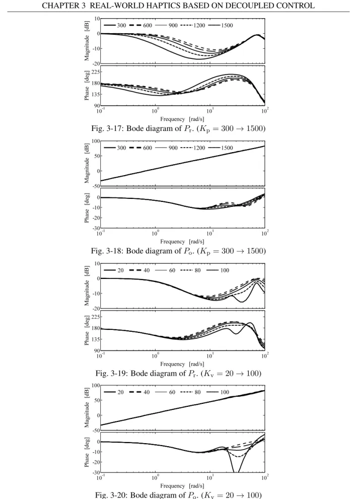
3-17 Bode diagram ofPr. (Kp= 300→1500) . . . . 56 3-18 Bode diagram ofPo. (Kp = 300→1500) . . . . 56 3-19 Bode diagram ofPr. (Kv= 20→100) . . . . 56 3-20 Bode diagram ofPo. (Kv = 20→100) . . . . 56 3-21 Bode diagram ofPr. (Kf = 0.3→1.5) . . . . 57 3-22 Bode diagram ofPo. (Kf = 0.3→1.5) . . . . 57 3-23 Bode diagram ofPr. (gX= 1→40) . . . . 57 3-24 Bode diagram ofPo. (gX= 1→40) . . . . 57
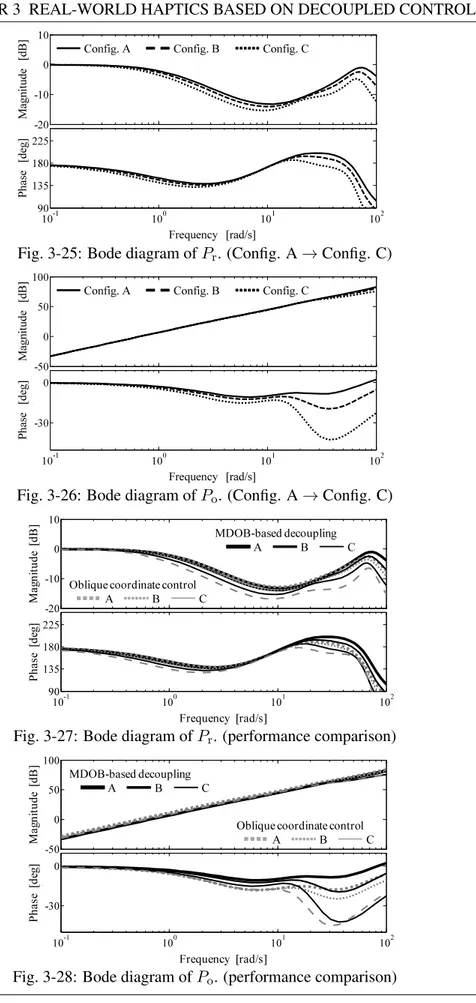
3-25 Bode diagram ofPr. (Config. A→Config. C) . . . . 58
3-26 Bode diagram ofPo. (Config. A→Config. C). . . . 58
3-27 Bode diagram ofPr. (performance comparison) . . . . 58
3-28 Bode diagram ofPo. (performance comparison) . . . . 58
3-29 Pole map of oblique coordinate control. (mM= 2.0→0.1) . . . . 59
3-30 Pole map of MDOB-based decoupling. (mM= 2.0→0.1) . . . . 59
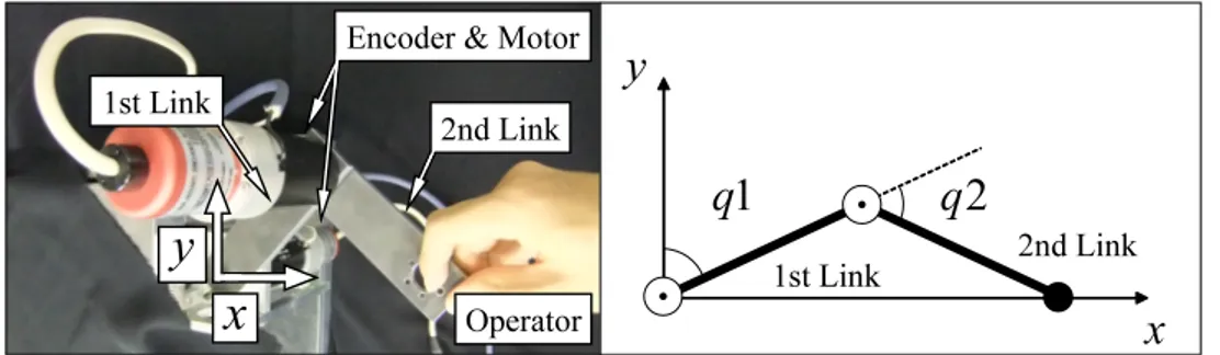
3-31 Experimental setup on master side. (two-link manipulator) . . . . 62
3-32 Experimental setup on slave side. (linear forceps robot) . . . . 62
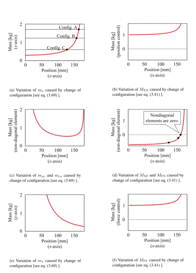
3-33 Relationship between configuration of manipulator and elements of equivalent mass ma-trices.. . . . 63
3-34 Experimental result of oblique coordinate control. (Config. A) . . . . 64
3-35 Experimental result of oblique coordinate control. (Config. B) . . . . 64
3-36 Experimental result of oblique coordinate control. (Config. C) . . . . 64
3-37 Experimental result of MDOB-based decoupling. (Config. A) . . . . 65
3-38 Experimental result of MDOB-based decoupling. (Config. B) . . . . 65
3-39 Experimental result of MDOB-based decoupling. (Config. C) . . . . 65
3-40 Comparison of control performances. . . . . 66
4-4 Setup of tendon-driven bilateral control system. . . . . 74
4-5 Concept of tendon-driven bilateral control system. . . . . 75
4-6 Block diagram of tendon-driven bilateral control system. . . . . 75
4-7 Free motion. . . . . 78
4-8 Contact motion. . . . . 78
4-9 Lifting a roll of Scotch tape such that it becomes vertical. . . . . 79
4-10 MP joint. . . . . 80
4-11 PIP joint. . . . . 81
4-12 DIP joint.. . . . 82
4-13 Force response when clicking a motion. . . . . 83
4-14 Response when a Scotch tape is removed. . . . . 84
4-15 Block diagram of force control. . . . . 85
4-16 Force response.. . . . 86
4-17 Model of tendon-driven mechanism. . . . . 87
4-18 Overview of the proposed method. . . . . 89
4-19 Block diagram of tendon-driven robotic system with DOB and RFOB. . . . . 91
4-20 Block diagram of bilateral controller.. . . . 93
4-21 Experimental setup (linear motor side). . . . . 95
4-22 Experimental setup (pulley side).. . . . 95
4-23 Experimental result (without elongation compensation). . . . . 97
4-24 Experimental result (with elongation compensation).. . . . 98
4-25 Wearable master robot hand. . . . . 99
4-26 Setup of the thrust wire. . . . . 99
4-27 Slave forceps robot. . . . . 100
4-28 Block diagram. . . . . 103
4-29 Experimental setup. . . . . 106
4-30 Extraction of grasping motion. . . . . 107
4-31 Result of principal component analysis. . . . . 107
4-32 Position response in modal space. . . . . 110
4-33 Force response in modal space.. . . . 110
4-34 Enlarged view of response (aluminum). . . . . 110
5-1 Flow of proposed method. . . . . 114
5-5 Master and slave robots. . . . . 121 5-6 Structure of finger. . . . . 121 5-7 Flexible actuator. . . . . 122 5-8 Motion classification. . . . . 123 5-9 Classification results. . . . . 127 5-10 Classification performance. . . . . 131
5-11 Model of the handling robot. . . . . 132
5-12 Entire block diagram. . . . . 137
5-13 Slope constraint. . . . . 139
5-14 Example of optimum path. . . . . 140
5-15 Experimental setup. . . . . 141
5-16 Reference patterns acquired from grasping action component. (a) Position reference pattern. (b) Force reference pattern. . . . . 141
5-17 Effects of change in force. (a) Position response. (b) Force response. (c) DP value. . . . 142
5-18 Effects of change in position. (a) Position response. (b) Force response. (c) DP value.. . 143
5-19 Effects of change in speed. (a) Position response. (b) Force response. (c) DP value. . . . 143
5-20 Experimental results of the difference in the number of motion. (a) Position response. (b) Force response. (c) DP value.. . . . 144
5-21 Effects of modal transformation. (a) Position response in the actuator space. (b) Position response in the component modal space. (c) Force response in the actuator space. (d) Force response in the component modal space. (e) DP values. . . . . 145
5-22 Application to power-assist system. (a) Position response. (b) Force response. (c) DP value.. . . . 146
6-1 Motion data collection system using bilateral control system. . . . . 154
6-2 Conventional motion data reproduction system. . . . . 157
6-3 Flowchart. . . . . 158
6-4 Proposed motion data reproduction system. . . . . 162
6-5 Experimental setup of 2-DOF forceps robot which can perform translational motion and grasping motion. . . . . 164
6-6 Validation of effectiveness of DP in stiffness estimation. . . . . 165
6-7 Experimental results of bilateral control. . . . . 166
6-8 Experimental results of scaled bilateral control. . . . . 167
position as that in the recording phase). . . . . 170
6-12 Experimental results of motion-reproducing system (phantom was located far from its position in the recording phase). . . . . 171
6-13 Experimental results of motion-reproducing system (phantom was located near from its position in the recording phase). . . . . 172
6-14 Research outline . . . . 173
6-15 Block diagram of teleoperation. . . . . 174
6-16 Experimental setup. . . . . 176
6-17 Example of estimation results. . . . . 178
6-18 Results of simulation and estimated stiffness. . . . . 182
6-19 Basic parameters estimated in simulation. . . . . 182
6-20 Experimental results using robotic operator and estimated stiffness. . . . . 185
6-21 Basic parameters estimated using robotic operator. . . . . 185
6-22 Experimental results for human operator and estimated stiffness. . . . . 187
6-23 Estimated basic parameters for experiment by human operator. . . . . 187
7-1 Outline of proposed system. . . . . 195
7-2 Outline of this approach. . . . . 196
7-3 Signal-flow diagram of bilateral control system. . . . . 197
7-4 Signal-flow diagram of motion-reproducing system proposed in [1]. . . . . 199
7-5 Signal-flow diagram of motion-reproducing system proposed in [2]. . . . . 200
7-6 Signal-flow diagram of conventional compensation method. . . . . 201
7-7 Signal-flow diagram of proposed time-scaling method.. . . . 202
7-8 Process of linearly-interpolation for slow loading speed. . . . . 203
7-9 Process of thinning out and skipping for fast loading speed. . . . . 203
7-10 Result of bilateral control. (a) Position response. (b) Force response. . . . . 204
7-11 Reproduction using [1] without difference in environmental location. (a) Position re-sponse. (b) Force rere-sponse.. . . . 206
7-12 Reproduction using [2] without difference in environmental location. (a) Position re-sponse. (b) Force rere-sponse.. . . . 206
7-13 Reproduction by conventional compensation method. (a) Position response. (b) Force response. . . . . 207 7-14 Reproduction by proposed time-scaling method. (a) Position response. (b) Force response.207
7-16 Reproduction using [2] with difference in environmental location. (a) Position response.
(b) Force response. . . . . 209
7-17 Reproduction by conventional compensation method with difference in environmental location. (a) Position response (b) Force response. . . . . 210
7-18 Reproduction by proposed time-scaling method with difference in environmental loca-tion. (a) Position response (b) Force response. . . . . 210
7-19 Structure of finger. . . . . 211
7-20 Overview of robot hand. (a) wire arrangement of master hand. (b) wire arrangement of slave hand. . . . . 211
7-21 Block diagram of whole control system. . . . . 214
7-22 Block diagram of action realization. . . . . 218
7-23 Snapshot of experiments concerning motion extraction. . . . . 220
7-24 Snapshot of experiments concerning motion reproduction. . . . . 220
3.1 Configuration of ABC. . . . . 34
3.2 Configuration of GMC.. . . . 35
3.3 Experimental parameters. . . . . 37
3.4 Parameters.. . . . 53
3.5 Configurations of master manipulator. . . . . 61
4.1 Four tasks that tendon-driven bilateral control system perform. . . . . 74
4.2 Parameters in experiment. . . . . 77
4.3 Remove the Scotch tape. . . . . 84
4.4 Experimental parameters. . . . . 96
4.5 Results of principal component analysis. . . . . 108
4.6 Experimental parameters. . . . . 108
4.7 Parameters for transformation matrix. . . . . 109
5.1 Parameters in experiments. . . . . 126
5.2 Classification rate. . . . . 128
5.3 Cosine similarity between reference vectors. . . . . 128
5.4 Combination motions. . . . . 129
5.5 Recognition rate. . . . . 129
5.6 Recognition rate using ideal reference. . . . . 130
5.7 Difference between each motion and the reference pattern.. . . . 142
6.1 Experimental parameters. . . . . 163
6.2 Hybrid angle and control impedance.. . . . 175
6.3 Parameter setup of human motion. . . . . 180
6.4 Parameters used in this study. . . . . 181
7.1 Parameters used in this chapter. . . . . 204
Introduction
Chapter 1 presents the background and the objective of this dissertation. This chapter also presents previous studies related to the subject of this dissertation.
1.1
Background of This Dissertation
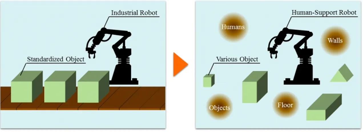
In recent years, the use of robots for factory automation has led to improved productivity, which leads to an increased standard of living. Robotics has shown rapid progress around the industrial field until now. In contrast, robots are expected to improve our quality of life by supporting human motions in the future for the urgent problem of aging societies with falling birthrates and labor shortages [3–6] as shown in Fig. 1-1. This urgent problem requires fundamental innovation. If a breakthrough in the solution is not brought immediately, the aging societies with falling birthrates and labor shortages cause the following serious problems:
(1) Reduction in the number of skilled person. (2) Increase in care burden.
(3) Decline in young labor force.
One of the great possibility is robotic human assistance. To support human motions and to act as physical agent, robots are required to operate in human environments. Here, “environment” refers to the objects with which robots make contact in their range of movement. Specifically, the environment includes
Fig. 1-1: Emerging roles of robots.
Fig. 1-2: Physical interaction between human, robot, and environment.
target objects, obstacles, floors, and walls. The term “human environment” refers to an environment that includes humans in the robot’s range of movement. In many cases, the human environment is the space in which we spend daily lives (e.g., kitchens, living rooms, and bedrooms). The study of robots working in the human environment includes indoor robots [7], physiotherapy robots [8], electric bicycles [9] and electric wheelchairs [10]. Indoor robots have a three-fingered robot hand and open doors like humans do [7]. Physical therapy robots display human joint torque and muscle force during exercise to improve rehabilitation performance [8]. Electric bicycles and electric wheelchairs reduce the force necessary to drive [9, 10]. Thus, a variety of robots has been actively researched for use in daily lives. However, the working area of robots still does not go beyond the bounds of the conventional numerically-controlled machine tools, which can treat only standardized objects. The problem standing in the way of development of robotics is “adaptability.”
Recent robots have been developed from numerical control aimed at precise positioning. Control stiff-ness has been increased as much as possible to be unaffected by external disturbance. However, what
is critically-needed now is adaptive force control. Humans are living in a world of physical interaction. Robots are also held by physical interaction. Humans, robots, and environment have to be in physical contact with each other as shown in Fig. 1-2. In human environment, everything is unstructured ob-ject. Even if there is a manufactured object, the size includes product tolerance. Hence knowing the precise position/size of the target object is definitely impossible. Position control and force control have following characteristics:
• Position control
– This is quite exclusive control and actively makes a plant move to a desired position regard-less of the status of the target environment.
• Force control
– This is highly adaptive control. The position of a plant is not defined and is determined by the character of environment.
If contact motion is performed by using only position control scheme, the target object is going to be broken. Humans achieve their own motions by changing composition of the position control and the force control with every moment. In order to artificially realize adaptive human motion, the composition of the position control and the force control must be designed. One of the effective approach is based on “functionality” [11, 12]. This approach has been used in a field of robotic control. Concept of the functionality in this dissertation is as explained below. To make the concept of functionality clear, Fig. 1-3 and Fig. 1-4 shows the equivalence between electric system and robotic system. For example, in electric systems, personal computer system consists of many units such as print unit and display unit. The units also consists of a lot of circuits. Furthermore, the circuits are composed of a combination of many circuit elements. In this way, electric systems have hierarchy of components. A roles of total system are decomposed into functions, and the functions are assigned to the lower components. Here, “System role” and “Function” are defined as follows:
Definition 1 “System role” is a description of the requirement from a user to a robot control system. Definition 2 “Function” is a required role of units, circuits, and elements.
Actual circuits are made to satisfy required objective. The circuits are provided to achieve functions by combining physical characteristics of circuit elements. To design a circuit possessing desired function,
designer only have to know what and how circuit element should be connected. In other word, necessary informations are as follows:
• Structure of the connected branches.
• Physical characteristic of branch constructing circuit.
The former is expressed by incidence matrix or topological matrix. The latter is determined by circuit constant and controlled electrical source. As mentioned above, functionality is a way to design total system by decoupling the system into simplified components.
As in the case of electric systems, robotic systems can be decomposed into simple components. For example, hand-over system requires pick and place motion. The pick and place motion consists of precise manipulation and adaptive grasping. Furthermore, the manipulation/grasping are composed of a combination of elements. In this way, robotic systems also have hierarchy of components. as with the electric system, a roles of total system are decomposed into functions, and the functions are assigned to the lower components.
Motions are generated to satisfy required objective. In case requiring stiff motion such as cutting operation, position control is used. In contrast, in case requiring adaptive motion such as grasping, force control is utilized. To achieve desired function, designer only have to know what and how motion element should be connected. In other word, necessary informations are as follows:
• Structure of required motion.
• Desired physical quantity such as movement distance and grasping force.
The former is expressed by modal transformation matrix. The latter is determined by human impedance, environmental impedance, controlled position source, and controlled force source. As mentioned above, the concept of functionality is also useful to design motion control system, as a designer easily get a grip on the system and modify the components. This approach have much better prospects than designing the entire system all together, as a designer have only to design the minimum components separately. The detail is described in Section 3.
1.2
Objective
The objective of this dissertation is clarifying when and how humans integrate position control and force control. Structure and physical quantity such as force of human motion are changing from moment
Fig. 1-3: Decomposition of electric system.
to moment. If the structure and physical quantity are clarified, the obtained results make it possible to artificially realize adaptive human motion.
Analyzing and understanding human motions have other two important implications. •Understanding target
•Improving ability of robots
Since the support target is nothing less than human, understanding human is important. If human motions are precisely measured and extracted, the supported persons can know failure of their body and motion. Furthermore, by using the processing results of the extracted information, robots can understand the state of target person, and can recognize what he/she wants to do. It makes it possible for robots to provide service appropriate for the situation.
In addition, from the analytical results, the implicit knowledge included in the human motions can be clarified. The obtained knowledge can be a key technology to make robots acquire human-like ability. Consequently, human-like dexterous and adaptable motions can be artificially realized by the robots. In other words, understanding of how humans work may enable the development of robots that can work like a human [13–16]
Fig. 1-4: Decomposition of robotic system.
1.3
Approach
This dissertation proposes a quite novel concept and approach for artificial realization of adaptive human manipulation. This dissertation expresses and treats human motions on the basis of functionality. In accordance with the abovementioned strategy, this study accomplishes artificial realization of adaptive human manipulation by dividing into four parts as follows:
•Extraction of Human Motion •Processing and Recognition •Analysis and Decomposition
•Artificial Realization of Adaptive Human Manipulation
Through this approach, this dissertation realizes adaptive human motion. The realized motion has high adaptability and performs removal operation of nuts in practice.
Fig. 1-5 shows the expected future that lies ahead of this dissertation. The innovations provided by this technology are as follows:
(1) Robotic systems can extract and preserve skillful human techniques. The recorded motion data is useful for education and training. Therefore, the reduction in skilled person is stopped.
Fig. 1-5: Expected future that lies ahead of this dissertation.
(2) Robotic systems can recognize and understand the situation from motion data. The robotic systems can provide support adequate to what he/she wants to do. Therefore, the caregiver burden is decreased.
(3) Robotic systems can realize human motions. As the reconstructed human motions are both precise and adaptable, robotic systems can perform various tasks. Therefore, they are able to act as an agent of young labors.
1.4
Chapter Organization
Fig. 1-6 shows the chapter organization. Chapter 2 describes fundamental technologies of motion control. Chapter 3 explains the research field of real-world haptics: it reviews the progress of research on real-world haptics. The following chapters are on the basis of the real-world haptics. In addition, chapter 3 shows a decoupling strategy for position and force control on the basis of modal space disturbance observers. This chapter also shows analytical results of the performance and the stability. The utility of
Proposal:
Reverse Engineering of Human Motion
Chapter 1 Introduction
Chapter 3
Real-World Haptics Based on Decoupled Control
Chapter 8 Conclusions
Chapter 2
Fundamental Technologies of Motion Control
Chapter 7
Artificial Realization of Adaptive Human Manipulation - Time-Scaled Reconstruction
- Force-Based Reconstruction Chapter 4
Extraction of Human Motion - Acquisition of Haptic Data - Extraction of Motion Feature
Chapter 5 Processing and Recognition - Recognition of Combined Motion - Recognition and Real-Time Assist
Chapter 6
Analysis and Decomposition - Stiffness Analysis of Motion - Elemental Separation
Fig. 1-6: Chapter organization.
the proposed method is experimentally verified by using a multi-degrees-of-freedom (DOF) manipula-tor. Chapter 4 describes a developed 11-DOF master-slave robot hands using tendon-driven mechanisms. Furthermore, a bilateral control system for tendon-driven robots is proposed. The transmission perfor-mance of the proposed system is experimentally verified. Chapter 4 also explains compensation of joint angle error caused by tendon elongation. This proposal is applied to a bilateral control system, and the validity is confirmed by experiments. In addition, Chapter 4 shows a bilateral control technique facilitat-ing intuitive operation. The technique is based on motion features of an operator expressed by principal component analysis. Chapter 5 presents a recognition method of human motions using dynamic program-ming pattern-matching algorithm. The validity of this recognition method is experimentally verified by using a 5-DOF master-slave robot hands. This chapter also describes an application of above-mentioned recognition method to modal space. In the experiments, the proposed method is applied to grasping motions. Chapter 5 confirms that the proposed method can trigger scaled bilateral control and assists
grasping force of the operator in real-time. Chapter 6 explains a proposed stiffness estimation system using scaled bilateral control. The utility of the proposed method is experimentally verified by using a haptic forceps robot. This chapter also shows a method to clarify the features of human motions by elementally separating haptic information on the basis of the principle of motion control. Chapter 7 presents a time-scaling technology to adapt to different location of target objects. This proposal shows usefulness especially in duration of the contact and amplitude of force. Furthermore, chapter 7 describes reproduction method of human actions. The utility of the proposed method is experimentally verified by applying to a removal operation of a nut. Chapter 7 confirms that the realized motion can remove the nut regardless of the size and shape. Chapter 8 summarizes and concludes this dissertation.
Nomenclature
DOB Disturbance observer DOF Degree-of-freedom RFOB Reaction force observer
WOB Work space disturbance observer MDOB Modal space disturbance observer RMSE Root mean square error
HDARH Haptic data acquisition robot hand TDBC Tendon-driven bilateral control system MP Metacarpophalangeal
PIP Proximal interphalangeal DIP Distal interphalangeal
ABC Acceleration-based bilateral control GMC Grasping and manipulating control PCA Principal component analysis CM Combination motion
DP Dynamic programing
PPV Positive predictive value NPV Negative predictive value
x,X Position
f,F Force
fl Load force
fmotor Generative force
fg(x) Gravity force
fb(x,x˙) Sum of inertial force, Coriolis force, and friction force
m,M Mass
Mt Equivalent mass
g Cutoff frequency
p Equivalent acceleration disturbance
s Laplace operator
ke Environmental stiffness
de Environmental viscosity
Ze Environmental impedance
d(i, j),d(i, j, t) Local distance, partial distance kc Control impedance
Kc Control stiffness
Dc Control viscosity
Po Operationality
Pr Reproducibility
τint Interactive torque vector
τext Reaction torque vector in force task
D Viscosity coefficient matrix
q Joint angle vector ˙
q Angular velocity vector
τc Coulomb friction vector
I(q) Joint inertia matrix
diagI(q) Diagonal matrix whose diagonal elements have the diagonal elements ofI(q)
In Nominal joint inertia matrix
Kt,Kt Torque coefficient, torque coefficient matrix
Ktn,Ktn Nominal torque coefficient, nominal torque coefficient matrix
H Hybrid matrix
Ia,Ia Torque current, torque current vector
I Unit matrix
x Position vector in work space
J(q) Jacobian matrix
Jt Modal transformation matrix, task Jacobian
f Force vector in the work space
τ Torque vector in the joint space
mn Equivalent mass matrix in the work space
Cp Position controller
Cf Force controller
K1, K2 Feedback gain
Kp Position feedback gain
Kv Velocity feedback gain
Kf Force feedback gain
Gt Coordinate transformation matrix
T Transformation matrix k1 Start time of motion
k2 End time of motion
V Covariance matrix
M Input combined motion pattern R Reference combined motion pattern
GP Position input pattern
RP Position reference pattern
RF Force reference pattern
DP Recorded position data
DF Recorded force data
α, β Scaling ratio α(in chapter 5) Mismatch penalty g(i, j),g(i, j, t) Cumulative distance D(in chapter 5) DP value
I Lengths of the input combined motion pattern J Lengths of the reference combined motion pattern p[d,k] Position transformed into modal space
q[d,k] Force transformed into modal space
k[d,k] Estimated stiffness
c[d,k] Estimated force offset
Rh(θh) Rotation matrix
Rh(θh) Rotation matrix
ktip Unintended stiffness
ˆ
kc Controlled and conscious stiffness
e Error signal
V Loading speed
r Radius of joint pulleys
N Matrix for null space calculation
u[k] Eigenvector ε[k] Eigenvalue
ˆ
η[d,k] Estimated parameter vector
ξ[d,k] Observation vector λ[d,k] Trace gain Γ,Λ Selection matrix λ1, λ2 Eigenvalue ∆ Modeling error ϕ Hybrid angle ¯ Average ˜ Deviation ˆ Estimation Superscript ref Reference res Response cmd Command dis Disturbance
trans Translational motion gras, grasp Grasping motion
ext External
th Thumb finger
in Index finger
mi Middle finger
save Saved motion data
Subscript record Recorded motion data dob Disturbance observer rfob, reac Reaction force observer ten Tension control
joi Joint control tor Torque control ang Angle control
work Work space
n Nominal value
dis Disturbance
dif, D Differential mode
com, C Common mode
int Interactive ext Reaction c Coulomb friction m, M Master system s, S Slave system r Right side l Left side b Bilateral control h Human
hpf High pass filter
int Internal
cmd Command
mode Modal space
This dissertation is written in time domain unless otherwise stated.
Fundamental Technologies of Motion
Control
2.1
Introduction
In this chapter, fundamental technologies for motion control of robotic systems are described. The main objective of the motion control is to control position and force. Acceleration control plays a critical role to deal with position and force. Acceleration derived from force divided by inertia and second order differential of position. Because of this, the acceleration control makes it possible to handle position control and force control in unified framework. The acceleration-based motion control has a significant meaning in this dissertation, as this dissertation employs robotic system with acceleration-based control to extract and reconstruct human motion. Section 2.2 shows a model of actuators and explains a concept of disturbance. Section 2.3 introduces a disturbance observer, which is a helpful technique to achieve acceleration control. Section 2.4 presents a technique to estimate external force on the basis of the disturbance observer. Section 2.5 shows specific configurations of acceleration control. Section 2.5.1 and Section 2.5.2 describe a position control system and a force control system, respectively. This chapter is finally concluded in section 2.6.
2.2
Modeling of Actuator
This chapter shows a modeling of linear actuators. The motion equation is obtained as
+
−
motorf
ref aI
lf
resx
&
&
x
&
resx
resMotor
tK
m
1
s
1
s
1
Fig. 2-1: Dynamics of linear motor.
where them, thex, thefl, and thefmotor denote the motor mass, the position, the load force, and the force generated by an actuator, respectively. The load forceflis expressed as
fl=fext+fg(x) +fb(x,x˙). (2.2) Thefext and thefg(x)denote the external force and the gravity force, respectively. Thefb(x,x˙)is the sum of the inertial force, Coriolis force, and friction force.
The generated force is obtained by multiplication of the armature current and the thrust coefficient. This dissertation assumes that the armature current is exactly the same as the current reference,
fmotor =KtIa=KtIaref. (2.3)
The motion equation is restated as
mx¨=KtIaref − {
fext+fg(x) +fb(x,x˙)
}
. (2.4)
Fig. 2-1 shows the block diagram of the motor dynamics. The parameters of eq. (2.4) (i.e. the massm and the thrust coefficientKt) vary according to the state of the robot and the distribution of the magnetic
flux. When the differences between the nominal values and the real values are expressed by∆m and ∆Kt, the following equations are obtained,
m = mn+ ∆m, (2.5)
Kt = Ktn+ ∆Kt, (2.6)
where the subscriptndenotes the nominal values. Since the disturbance is the sum of the load forcefl and the effect of the parameter variations, the disturbance is presented as
fdis = fl+ ∆mx¨−∆KtIaref
+
−
motorf
ref aI
disf
resx
&
&
x
&
resx
resMotor
tnK
n1
m
s
1
s
1
Fig. 2-2: Dynamics of linear motor using nominal mass value.
When the parameter variations are considered, the motion equation of eq. (2.1) is rewritten as
(mn+ ∆m)¨x= (Ktn+ ∆Kt)Iaref −fl. (2.8)
By subtracting eq. (2.7) into eq. (2.8),
mnx¨ = KtnIaref −(fl+ ∆mx¨−∆KtIaref)
= KtnIaref −fdis (2.9)
+ − motor f ref a I l f res x&
& x&res xres
t K m 1 s 1 s 1 + − tn K mns dis ˆf
Fig. 2-3: Disturbance calculation based on velocity response.
+ − motor f ref a I l f res x&
& x&res xres
t K m 1 s 1 s 1 + − tn K mns dis ˆf dis dis g g + s
DOB
Fig. 2-4: Disturbance estimation in consideration of measurement noise.
2.3
Disturbance Observer
From eq. (2.9),
fdis=KtnIaref−mnx ¨ (2.10)
is obtained. Equation (2.10) shows that the disturbance can be derived by the current reference and the velocity. Fig. 2-3 presents the block diagram of the disturbance calculation. By using the calculated disturbance, suppression of the disturbance becomes possible in feedforward manner. Since the derivation enhances the noise effect especially in the high frequency domain, a low pass filter (LPF) is employed.
+
−
motorf
ref aI
lf
resx
&
&
x
&
resx
rest
K
m
1
s
1
s
1
+
+
tnK
g
dism
n disˆf
dis disg
g
+
s
DOB
g
dism
n−
+
Fig. 2-5: Disturbance calculation using integrator.
Fig. 2-4 shows the disturbance estimation with first-order LPF. The disturbance is estimated as fˆdis(s) = gdis
s+gdis
fdis(s). (2.11) Fig. 2-5 shows a equivalent block diagram of Fig. 2-4. In Fig. 2-5, an integrator is utilized instead of the differentiator. The inside of the dashed line is referred to as disturbance observer (DOB). The compensation current for the disturbance suppression is derived from the disturbance estimated in the structure of Fig. 2-3. When the compensation current is fed back into the system, the disturbance is canceled as shown in Fig. 2-6. If the sampling period is short enough, this structure can be regarded as feedforward equivalently.
+
−
motorf
ref aI
lf
resx
&
&
x
&
resx
rest
K
m
1
s
1
s
1
+
+
tnK
g
dism
n disˆf
dis disg
g
+
s
DOB
g
dism
n−
+
tn1
K
tn nK
m
cmpI
refI
++
refx
&
&
Fig. 2-6: Disturbance feedback.
In the low frequency domain, which is lower than the cutoff frequency gdis, the disturbance is
sup-pressed by DOB. In contrast, in the high frequency domain, the disturbance affects the system. Therefore, Fig. 2-6 is transformed as Fig. 2-7 equivalently. In Fig. 2-7, the disturbance passes through the high pass filter (HPF) and input into the system. The HPFGs(s)is expressed as
Gs(s) = s s+gdis . (2.12) Here,pis defined as p(s) = s2xref(s)−s2xres(s) = m−n1Gs(s)fdis(s). (2.13)
pdenotes the difference between the acceleration reference and the actual acceleration. By usingp, ro-bust control system is shown as Fig. 2-8. pis error of the robust control system. This error is treated in acceleration dimension and is referred to as equivalent acceleration disturbance. The equivalent accel-eration disturbancep depends on the abovementioned HPFGs(s). Although the cutoff frequencygdis
+
−
motorf
ref aI
disf
resx
&
&
x
&
resx
restn
K
n1
m
s
1
s
1
tn nK
m
refx
&
&
disg
+
s
s
Fig. 2-7: Equivalent block diagram of Fig. 2-5.
+ −
p
res
x
&
&
x
&
resx
ress
1
s
1
refx
&
&
Fig. 2-8: Equivalent acceleration disturbance.
2.4
Reaction Force Observer
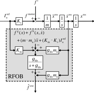
Reaction force observer (RFOB) is a structure, which estimates the external force by using DOB. Fig. 2-9 shows the RFOB. RFOB extracts the external force by subtracting thefg(x), thefb(x,x˙), and
the parameter errors from the estimated disturbance, although the subtracted values should be identified in advance.
+
−
motorf
ref aI
lf
resx
&
&
x
&
resx
rest
K
m
1
s
1
s
1
+
+
tnK
g
dism
n extˆf
dis disg
g
+
s
RFOB
g
dism
n−
+
ref a t tn n b g)
(
)
(
)
,
(
)
(
I
K
K
x
m
m
x
x
f
x
f
‐
‐
+
+
+
&
&
&
−
Fig. 2-9: Reaction force observer.
2.5
Motion Control System
To discuss about the references, a second order system with DOB is considered.
2.5.1 Position Control
In the ideal position control, following two characteristics should be achieved: •Characteristic of command-tracking.
•Characteristic of disturbance rejection.
The first characteristic means: position response should track the desired position, and the second one means: the disturbance should be rejected. In a system shown in Fig. 2-10, the transfer functions are derived as xres(s) xref(s) = K1K2 s2+K 1s+K1K2 , (2.14) x res(s) fdis(s) = p(s) s2+K 1s+K1K2 . (2.15)
+ −
p
res
x
&
&
x
&
resx
ress
1
s
1
refx
&
&
1K
2K
refx
&
refx
Velocity
Feedback
Position
Feedback
Disturbance
Observer
+
−
+
−
Fig. 2-10: Position control system.
+−
p
res
x
&
&
x
&
resx
ress
1
s
1
1K
2K
cmdx
+
−
+
−
+
+
+
cmdx
&
cmdx
&
&
Fig. 2-11: Position control system with feedforward.
eq. (2.14) to1, the feedforward of the velocity and the acceleration is added as presented in Fig. 2-11. By this feedforward the transfer function becomes
xres(s) =xcmd(s)−(s2+K1s+K1K2)−1p(s). (2.16)
Since DOB suppresses almost all the disturbance, a little error existing in the high frequency domain is attenuated by the control poles, which are determined by the gainsK1andK2.
p
resx
cmdx
−
cmdx
&
cmdx
&
&
Plant
disˆf
+
+
+
Command
Following
Disturbance
Rejection
Controller
Fig. 2-12: Relationship between feedforward and disturbance observer.
As shown in Fig. 2-12, roughly speaking, DOB takes a role of the disturbance rejection and the feedforward is in charge of the command-following. This structure makes it possible to design these characteristics independently.
+−
p
res
x
&
&
x
&
resx
ress
1
s
1
cmdf
+
−
extf
fC
refx
&
&
Fig. 2-13: Force controller with DOB.
2.5.2 Force Control
The aim of force control is to control the environmental reaction force to the desired value. From the law of action and reaction, the environmental reaction force is the same as the force, which the end effector applies to the environment. Note that, the applying force is different from the generated force, as the applying force includes not only the applying force but also the gravity force, the friction force, and so on. The acceleration reference of the force controlx¨ref is calculated as
x¨ref =Cf(fcmd−fext), (2.17)
where thefcmd, thefext, and theCf denote the force command, the external force, and the force
con-troller. Fig. 2-13 shows the block diagram of the force control system using the disturbance observer. Here, the force controllerCf is assumed as a proportional controller
Cf =Kf, (2.18)
whereKf denotes the feedback gain. The relationship between the force command and the external force
is described as fcmd−fext= 1 Kf ¨ xres− 1 Kf p. (2.19)
Equation (2.19) shows that if the feedback gain is large the error becomes small. The dimension ofKf
is1/kg. When the environment is assumed to be parallel connection of the spring element ke and the
damping elementde, the environment is expressed as
fext(s) = (des+ke)xres(s). (2.20)
From eq. (2.19) and eq. (2.20), the transfer function from the force command to the position response is obtained as xres(s) fcmd(s) = 1 1 Kfs 2+d es+ke . (2.21)
2.6
Summary
This chapter explained the fundamental technologies of motion control on the basis of acceleration control. Plants are always affected by disturbances such as load force and modeling error. Therefore, handling of the disturbances is a key issue. This chapter introduced the disturbance observer. Since the disturbance observer can derive and compensate the effect of the disturbance in acceleration dimension, this technique is quite helpful and important for motion control. This observer also makes it possible to adjust two characteristics separately. One is the characteristic of command-tracking. The other is the characteristic of disturbance rejection. In addition, this chapter described the structure of the reaction force observer, which can estimate the external force. This chapter also showed the concrete examples of the position control system and the force control system. The above-mentioned technologies make it possible to adjust the effect of the disturbance. While the disturbance observer possess the effect of disturbance suppression, the reaction force observer possess the effect of disturbance acceptance. As these technologies are utilized in the following chapters concerning the extraction, the analysis, and the reconstruction of human motion, the technologies explained in this chapter are quite important in this dissertation.
Real-World Haptics Based on Decoupled
Control
3.1
Introduction
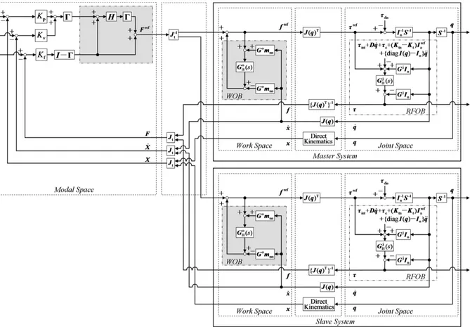
The first half of this chapter introduces the research field of real-world haptics that acts on real-world objects. This part also reviews recent technical advances in real-world haptics, such as functionality and oblique coordinate control. As a catalyst for real-world haptics, a principle of this research area is explained through two simple examples: acceleration-based bilateral control and grasping/manipulating control. These two examples and the cited papers offer the view that a wide variety of system roles can be realized by combining pure position control and pure force control with an appropriate coordinate transformation. Real-world haptics has the capability of contributing toward supporting human activities. The second half of this chapter extends the diagonalization method on the basis of the modal space disturbance observer (MDOB) for application to a multi-degree of freedom (DOF) system. The aim of this method is to suppress the interference between the position and force control systems, and to realize a bilateral control system. The utility of the proposed method is experimentally verified by using a multi-DOF manipulator. Higher performance of the MDOB-based decoupling method compared with oblique coordinate control is confirmed. Conventional oblique coordinate control causes oscillation in cases where the modeling error is large and the cutoff frequency of an observer is not high enough to change the system dynamics. On the other hand, the MDOB-based decoupling method becomes unstable when the difference in mass is large.
important technologies are introduced. Section 3.1.2 and 3.1.3 show two simple examples to generate concrete descriptions: Section 3.1.2 presents an acceleration-based bilateral control system, and Sec-tion 3.1.3 explains a grasping/manipulating control system. In both examples, contact with real-world objects is required. The experimental results are presented in Section 3.1.4. Section 3.2.1 presents an approach to realize a robust controller. Section 3.2.2 describes oblique coordinate control. Section 3.2.3 explains the use of MDOB with multi-DOF systems. Section 3.2.4 shows the analytical results of the performance and the stability. The experimental results are shown in section 3.2.5. This chapter is finally concluded in section 3.3.
3.1.1 Progress of Real-World Haptics
Haptics
Haptics is a research field that deals with information of physical interaction between humans and objects. Haptic information, unlike auditory and visual information, directly presents the size, shape, collision, and location of the objects [17]. For example, a haptic interface has been developed for med-ical simulations of palpation, which is a physmed-ical examination technique devised to check the state of health [18]. However, conventional studies on haptics generally consider only virtual environments [19]. In contrast, real-world haptics is a research field that deals with unstructured objects in the real world [20, 21]. Real-world haptics is expected to make breakthroughs with conventional numerical con-trol, which is not always suitable for adaptation to unknown environments.
Duality
In real-world haptics, controlling the stiffness of a manipulator end effector is important [22]. The control stiffnessκis expressed as
κ= ∂f
∂x, (3.1)
wherexandf denote the position and force, respectively. The control stiffness must be infinity under pure position control and zero under pure force control. Therefore, pure position control and pure force control cannot be achieved in the same direction at the same time.
Compliance Control and Hybrid Control
Two control methods that consider this duality are compliance control and hybrid control. Compli-ance control achieves intermediate control stiffness between infinity and zero [23, 24]. Hybrid control uses a directionally decoupled motion controller in the operational space [25, 26]. To improve hybrid control, a task description method has been proposed that is based on the construction of generalized task specification matrices to unify references to position control and force control [27].
Motion Control
To improve control systems such as compliance and hybrid control, an acceleration control [28] was developed to realize a robust motion controller. Disturbance observers (DOBs) [29] and sliding mode controls [30, 31] contribute to realizing high robustness.
Disturbance Observer
The DOB, in particular, makes it possible to realize a robust motion controller by estimating and suppressing disturbances that are input into a system: it facilitates decoupling of two kinds of charac-teristics: disturbance suppression and command following. The structure is a two-degrees-of-freedom (DOF) controller structure [32].
The DOB has another important feature: the estimated disturbance includes a reaction force from the environment. The reaction force observer (RFOB) extracts the reaction force from the disturbance [33]. One study on DOB and RFOB used a decoupling motion control strategy [34]. This strategy decouples motion controllers by determining the equivalent mass matrix in operational space.
Modal Transformation
To break down the overall information–including the position, velocity, and reaction force–into several components, the concept of modes has been introduced to motion control [35]. For example, modes were applied to a biped robot: environmental information measured from the bottom of the foot was decoupled into four modes: heaving, rolling, pitching, and twisting [36]. This decoupling also makes it possible to design controllers for each motion separately. In the study using a biped robot, the Hadamard matrix was utilized for modal transformation. However, the Hadamard matrix can only form modes with2n order (n ∈ R). Therefore, the modal transformation method was extended to deal with odd [37] or arbitrary numbers of modes [38, 39].
Fig. 3-1: Concept of functionality. Functionality
Proposed design methods for decentralized control include subsumption architecture [40] and multi-scale robot systems [41]: decentralized control is a promising method to realize complicated and large systems [42]. A decomposition transformation that reduces the total system into a form that can be con-trolled in blocks has been proposed [43]. The principle of superposition, which implies that a skilled motion can be resolved into elementary motions, was demonstrated [44]. A reduction method that de-composes an entire motion on the basis of a singular value [45] was developed.
Based on the demand for simplification of large-scale system design, the concept of modes was ex-tended, and “functionality” was proposed [46]. In this method, an entire complicated control system for realizing system roles is decoupled into simplified independent components that are defined as functions. In other words, the roles of the entire control system are represented as a superposition of these functions under the assumption that the functions are independent of each other. This property is referred to as functionality [11]. Functions are abstracted and expressed by the function mode. A DOB is applied to cancel the dynamic interference and ensure the independence of each function mode [47]. This design method was applied to a three-dimensional 18-DOF cooperative grasping manipulator, and the detailed design procedure was presented [12]. Fig. 3-1 shows motion realization based on the concept of func-tionality. Functionality has been used for reconfigurable robots [48], multibody mechanical systems [49], and bilateral control [50].
Fig. 3-2: Application examples. Oblique Coordinate Control
A more general theory was developed, named oblique coordinate control [51, 52]. This theory regards the control of tasks as problems of position/force hybrid control in oblique coordinates and shows that tasks can be realized by appropriate coordinate transformations [53, 54]. This method simply requires the design of a coordinate transformation matrix, which is a task Jacobian.
Application examples
These studies showed that diverse roles and tasks can be completed by combining pure position con-trol and pure force concon-trol with appropriate coordinate transformation. Furthermore, artificially designed coordinates make it possible to simultaneously realize both position and force control even if they are on the same axis. Typical applications (Fig. 3-2) include object tracking with different DOF manipu-lators using visual information [55], an 11-DOF tendon-driven robot hand [56], a two-link manipulator equipped with a biarticular muscle mechanism [57], a telerobotic-assisted bone-drilling system [58], and medical robots [59] such as a 16-DOF telesurgical forceps robot with haptics [60].
Fig. 3-3: Directional properties of human sensations.
3.1.2 Acceleration-Based Bilateral Control
Fig. 3-3 shows the directional properties of acoustic, visual, and haptic information. Today, methods already exist for acquiring auditory and visual information. Auditory information is extracted by using microphones and reproduced by using speakers. Similarly, visual information is recorded by cameras and then displayed on monitors. On the other hand, haptic sensations have a bilateral property because they are governed by Newton’s law of action and reaction in the real world. This bilateral property makes it difficult to realize a system role that involves contact with an unstructured environment.
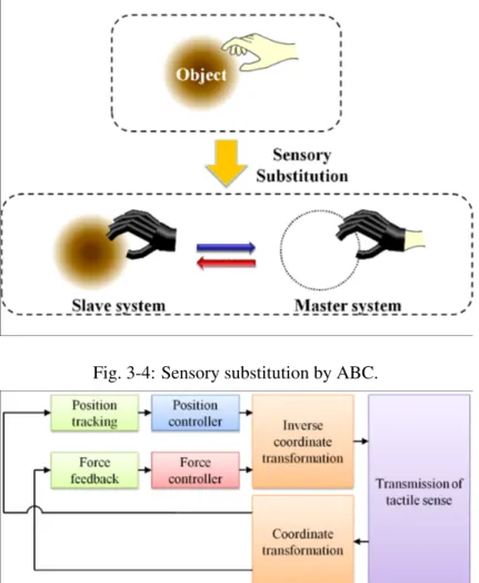
Bilateral control [61–63] is the most prominent example that requires a system role involving contact motion. In general, a bilateral control system consists of a master system operated by a human and a slave system that makes contact with an object [64], as shown in Fig. 3-4. The aim of the bilateral control system is tactile sense transmission to enable perception of the mechanical impedance of an object existing in a remote place.
Fig. 3-4: Sensory substitution by ABC.
Fig. 3-5: Overall block diagram of ABC system. Table 3.1: Configuration of ABC.
Function Modal space Control system
position tracking differential mode position control force feedback common mode force control
Acceleration-based bilateral control (ABC) is based on the concept of modes [65–67]. Fig. 3-5 shows the overall block diagram of ABC. To perform tactile sense transmission, position tracking and force feedback functions are required. In this method, the position tracking function is satisfied in the differen-tial mode, and force feedback function is fulfilled in the common mode. Table 3.1 lists the modal spaces and control systems corresponding to each function. The merit of this approach is not only the explicit controller design but also the high level of performance [68].
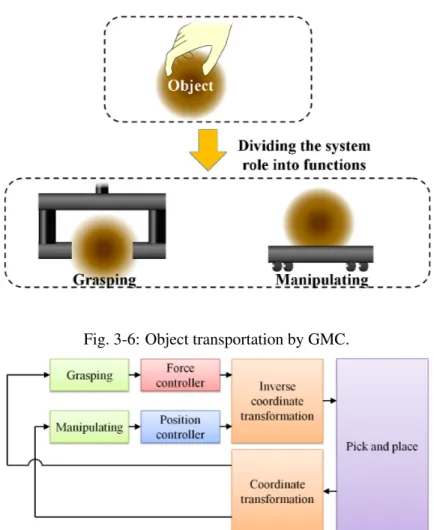
Fig. 3-6: Object transportation by GMC.
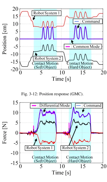
Fig. 3-7: Overall block diagram of GMC system. Table 3.2: Configuration of GMC.
Function Modal space Control system
adaptive grasping differential mode force control precise manipulating common mode position control
3.1.3 Grasping and Manipulating Control
Grasping and manipulating control (GMC) [12] is the most prominent example of a system role in-volving contact motion. The robot has to grip the target object softly enough to not break it. Furthermore, it needs to carry the target object to the desired position. Therefore, the roles of the system can be divided into the functions shown in Fig. 3-6. To perform the role of pick and place, adaptive grasping and precise
Fig. 3-8: Experimental setup (ABC).
manipulating functions are required [48]. In this method, the adaptive grasping and precise manipulat-ing functions are fulfilled in differential mode and common mode [39], respectively. Fig. 3-7 shows the overall block diagram of the GMC system. Table 3.2 lists the modal spaces and control systems corresponding to each function. While ABC uses a position controller in differential mode and force controller in common mode, GMC needs a force controller in differential mode and position controller in common mode.
3.1.4 Experiments
Experiments were conducted to verify the validity of the functionality-based approach. This section presents two kinds of experiments using the ABC system and using the GMC system. The position was measured by optical encoders, each set on a linear motor. The reaction force from the object was observed using RFOB without force sensors.
Experimental Setups
Fig. 3-8 shows the experimental setup of the ABC system. In this experiment, two linear motors were utilized, as the master system and slave system. An operator moved the master system, which is on the right side. The slave system pushed the object fixed on the left side.