CCNP Self-Study CCNP Practical Studies: Switching By Justin Menga
... Publisher: Cisco Press
Pub Date: October 08, 2003 ISBN: 1-58720-060-0
Pages: 984
Table of Contents | Index
Gain necessary hands-on experience implementing CCNP BCMSN concepts with this practical lab guide.
Lab configurations include explanations of equipment set-up and execution
Valuable reference tool for Catalyst switches, including shortcuts, caveats, and application of the most advanced features
Real-world scenarios represent the whole range of CCNP BCMSN 642-811 exam topics
CCNP Practical Studies: Switching (CCNP Self-Study) provides CCNP candidates with an in-depth, hands-on experience in configuring Cisco Catalyst switches. This practical guide shows intermediate level networkers how to apply the theoretical knowledge they have gained through CCNP coursework and exam preparation. Configuration labs performed within this book will cover all technologies tested on the BCMSN 642-811 exam, as well as a number of real world scenarios that will test users' overall understanding of multilayer switching. The labs come complete with full explanations, highlighting why the chosen commands and techniques are recommended.
In addition to applicable labs, this book also provides general information on various switching technologies, as well as tips, tricks, shortcuts, and caveats for deploying Cisco switching gear in production environments. This book also includes exercises (similar to traditional mathematics exercises) that will help readers internalize, practice, and memorize certain concepts and thought processes necessary to successfully deploy a switched network.
Part of the Practical Studies series from the Cisco Press, CCNP Practical Studies: Switching
CCNP Self-Study CCNP Practical Studies: Switching By Justin Menga
... Publisher: Cisco Press
Pub Date: October 08, 2003 ISBN: 1-58720-060-0
Pages: 984
Table of Contents | Index
Copyright
About the Author
About the Technical Reviewers
Introduction
Goals of this Book
Audience
Chapter Organization
How Best to Use This Book
Equipment Required for Practical Experience
Obtaining Equipment
How To Use This Book if You Do Not Have Access to This Equipment
Cisco Systems Networking Icon Legend
Command Syntax Conventions
Chapter 1. Switching Connectivity
Introduction to Cisco Catalyst Switches
Scenario 1-1: Installing a Cisco Catalyst Switch onto the Network
Scenario 1-2: Configuring Network Management Access to the Switch
Scenario 1-3: Configuring Ethernet Device Connectivity
Scenario 1-4: Configuring System Time
Scenario 1-5: Monitoring and Troubleshooting Device Connectivity
Summary
Chapter 2. VLAN Operations
Introduction
Scenario 2-1: Understanding Transparent Bridging
Scenario 2-3: Configuring VLANs
Scenario 2-4: Configuring the Management VLAN
Scenario 2-5: Configuring Extended-Range VLANs
Summary
Chapter 3. Trunking and Bandwidth Aggregation
Introduction
Scenario 3-1: Configuring VLAN Trunking Protocol
Scenario 3-2: Configuring Trunking Between Switches
Scenario 3-3: VTP Pruning
Scenario 3-4: Configuring EtherChannel
Summary
Scenario 4-4: Configuring Spanning Tree PortFast
Scenario 4-5: Configuring PortFast BPDU Guard
Scenario 4-6: Configuring PortFast BPDU Filter
Scenario 4-7: Configuring UplinkFast
Scenario 4-8: Configuring BackboneFast
Scenario 4-9: Improving Convergence and Load Sharing by Using a MultilayerTopology Scenario 4-10: Troubleshooting Spanning Tree
Summary
Chapter 5. Inter-VLAN Routing
Inter-VLAN Routing Architectures
Multilayer LAN Design
Scenario 5-1: Configuring Basic IP Routing
Scenario 5-2: Configuring Layer 3 Switching
Scenario Prerequisites
Summary
Chapter 6. Layer 3 Switching
Introduction to Layer 3 Switching
Cisco Catalyst 6000/6500 Switch Architecture
Scenario 6-1: Configuring MLS on the Catalyst 6000
6000/6500 Operating in Hybrid Mode
Scenario 6-3: Upgrading from Hybrid Mode to Native Mode on the Catalyst6000/6500
Scenario 6-4: Configuring CEF-Based Layer 3 Switching on the Catalyst6000/6500 Operating in Native Mode Summary
Chapter 7. Multicast Routing and Switching
Introduction
Scenario 7-1: Configuring PIM Dense Mode Multicast Routing
Scenario 7-2: Configuring PIM Sparse Mode and PIM Sparse-Dense ModeMulticast Routing Scenario 7-3: Multicast Traffic Control on the LAN
Scenario 7-4: Configuring IGMP Snooping
Scenario 7-5: Configuring Cisco Group Management Protocol (CGMP)
Summary
Chapter 8. Traffic Filtering and Security
Securing Management Access
Securing Network Access
Traffic Filtering
Scenario 8-1: Securing the Management Interface
Scenario 8-2: Enhancing Security by Using AAA
Implementing Quality of Service on Cisco Switches
Scenario 9-1: Configuring QoS Features
Summary
Chapter 10. Maintenance, Monitoring, and Troubleshooting
Scenario 10-1: Using IP and LAN Connectivity Tools
Scenario 10-2: Troubleshooting Workstation Startup Problems
Scenario 10-3: Troubleshooting the errDisable Status
Scenario 10-4: Password Recovery
Scenario 10-5: File Management on Cisco Catalyst Switches
Scenario 10-6: Capturing Traffic Using SPAN, RSPAN, and VACLs
Summary
Chapter 11. Comprehensive Switching Self-Study Lab
Part I: Configuring a Layer 2 Switching Infrastructure
Part II: Multilayer Configuration
Appendix A. Comprehensive Switching Self-Study Lab Part I Solution
Configuring a Layer 2 Switching Infrastructure Solution
Complete Configurations for Self-Study Lab Part I
Appendix B. Comprehensive Switching Self-Study Lab Part II Solution
Multilayer Configuration Solution
Complete Configurations for Self-Study Lab Part II
Copyright
Copyright© 2004 Cisco Systems, Inc.
Published by: Cisco Press
800 East 96th Street, 3rd Floor Indianapolis, IN 46240 USA
All rights reserved. No part of this book may be reproduced or transmitted in any form or by any means, electronic or
mechanical, including photocopying, recording, or by any information storage and retrieval system, without written
permission from the publisher, except for the inclusion of brief quotations in a review.
Printed in the United States of America 1 2 3 4 5 6 7 8 9 0
First Printing October 2003
Library of Congress Cataloging-in-Publication Number: 2001099911
Warning and Disclaimer
This book is designed to provide information about switching. Every effort has been made to make this book as complete and as accurate as possible, but no warranty or fitness is implied.
The information is provided on an "as is" basis. The authors, Cisco Press, and Cisco Systems, Inc., shall have neither liability nor responsibility to any person or entity with respect to any loss or damages arising from the information contained in this book or from the use of the discs or programs that may
The opinions expressed in this book belong to the author and are not necessarily those of Cisco Systems, Inc.
Feedback Information
At Cisco Press, our goal is to create in-depth technical books of the highest quality and value. Each book is crafted with care and precision, undergoing rigorous development that involves the unique expertise of members from the professional
technical community.
Readers' feedback is a natural continuation of this process. If you have any comments regarding how we could improve the quality of this book, or otherwise alter it to better suit your needs, you can contact us through e-mail at
[email protected]. Please make sure to include the book title and ISBN in your message.
We greatly appreciate your assistance.
Trademark Acknowledgments
All terms mentioned in this book that are known to be trademarks or service marks have been appropriately
capitalized. Cisco Press or Cisco Systems, Inc., cannot attest to the accuracy of this information. Use of a term in this book should not be regarded as affecting the validity of any
trademark or service mark.
Credits
Publisher John Wait
Executive Editor Brett Bartow
Cisco Representative Anthony Wolfenden Cisco Press Program Manager Sonia Torres Chavez Manager, Marketing Communications, Cisco Systems Scott Miller
Cisco Marketing Program Manager Edie Quiroz
Managing Editor Patrick Kanouse
Acquisitions Editor Michelle Grandin
Development Editor Andrew Cupp
Project Editor Marc Fowler
Copy Editor Kevin Kent
Technical Editors Andy Barkl
Henry Benjamin Steve Daleo Drew Rosen Jeff Saxe Peter Welcher
Team Coordinator Tammi Barnett
Book Designer Gina Rexrode
Cover Designer Louisa Adair
Compositor Mark Shirar
Corporate Headquarters
Cisco Systems, Inc. 170 West Tasman Drive San Jose, CA 95134-1706 USA
www.cisco.com
Tel: 408 526-4000
800 553-NETS (6387) Fax: 408 526-4100
European Headquarters
Cisco Systems International BV Haarlerbergpark
Haarlerbergweg 13-19 1101 CH Amsterdam The Netherlands
www-europe.cisco.com
Tel: 31 0 20 357 1000 Fax: 31 0 20 357 1100
Americas Headquarters
Cisco Systems, Inc. 170 West Tasman Drive San Jose, CA 95134-1706 USA
www.cisco.com
Tel: 408 526-7660 Fax: 408 527-0883
Asia Pacific Headquarters
Capital Tower
Cisco Systems has more than 200 offices in the following countries and regions. Addresses, phone numbers, and fax numbers are listed on the Cisco.com Web site at
www.cisco.com/go/offices.
Argentina • Australia • Austria • Belgium • Brazil • Bulgaria • Canada • Chile • China PRC • Colombia • Costa Rica • Croatia • Czech Republic Denmark • Dubai, UAE • Finland • France •
Germany • Greece • Hong Kong SAR • Hungary • India •
Indonesia • Ireland • Israel • Italy Japan • Korea • Luxembourg • Malaysia • Mexico • The Netherlands • New Zealand • Norway • Peru • Philippines • Poland • Portugal Puerto Rico • Romania • Russia • Saudi Arabia • Scotland • Singapore • Slovakia •
Slovenia • South Africa • Spain • Sweden Switzerland • Taiwan • Thailand • Turkey • Ukraine • United Kingdom • United States • Venezuela • Vietnam • Zimbabwe
Copyright © 2003 Cisco Systems, Inc. All rights reserved. CCIP, CCSP, the Cisco Arrow logo, the Cisco Powered Network mark, the Cisco Systems Verified logo, Cisco Unity, Follow Me
Browsing, FormShare, iQ Net Readiness Scorecard, Networking Academy, and ScriptShare are trademarks of Cisco Systems, Inc.; Changing the Way We Work, Live, Play, and Learn, The Fastest Way to Increase Your Internet Quotient, and iQuick Study are service marks of Cisco Systems, Inc.; and Aironet, ASIST, BPX, Catalyst, CCDA, CCDP, CCIE, CCNA, CCNP, Cisco, the Cisco Certified Internetwork Expert logo, Cisco IOS, the Cisco IOS logo, Cisco Press, Cisco Systems, Cisco Systems Capital, the Cisco Systems logo, Empowering the Internet
Step, GigaStack, Internet Quotient, IOS, IP/TV, iQ Expertise, the iQ logo, LightStream, MGX, MICA, the Networkers logo, Network Registrar, Packet, PIX, Post-Routing, Pre-Routing, RateMUX, Registrar, SlideCast, SMARTnet, StrataView Plus, Stratm, SwitchProbe, TeleRouter, TransPath, and VCO are registered trademarks of Cisco Systems, Inc. and/or its affiliates in the U.S. and certain other countries.
All other trademarks mentioned in this document or Web site are the property of their respective owners. The use of the word partner does not imply a partnership relationship between Cisco and any other company. (0303R)
Printed in the USA
Dedication
About the Author
Justin Menga is a dual-certified Cisco Certified Internetwork Expert (CCIE No. 6640) in the Routing and Switching and Security tracks. He has eight years of networking experience, working with many products from major vendors. Justin holds the premier qualifications for Cisco, Microsoft, and Check Point, demonstrating his understanding of both networks and
applications and the underlying security required for both.
He is employed as a network design consultant for Logical CSI in New Zealand, a global network integration company with offices in more than 40 countries worldwide. Previously, he was employed by Compaq Global Services in a similar role. He is responsible for the pre-sales support, design, and proof-of-concept testing for complex networks that require a broad mix of technologies. These technologies include routing, switching, network, and wireless security and Voice over IP. Recently, Justin became CCIE certified in the Security track,
demonstrating his diverse range of skills.
About the Technical Reviewers
Andy Barkl, CCNP, CCDP, has over 19 years of experience in the IT field. He's the owner of MCT & Associates LLC, a technical training and consulting firm in Phoenix, Arizona.
Henry Benjamin, CCIE No. 4695, is triple-CCIE-certified,
having attained Routing and Switching in May 1999, ISP Dial in June 2001, and Communications and Services in May 2002. He has more than 10 years experience with Cisco networks
including planning, designing, and implementing large IP
networks running IGRP, EIGRP, BGP, and OSPF. Recently, Henry previously worked for a large IT organization based in Sydney, Australia, as a key Network Designer, designing and
implementing networks all over Australia and Asia.
In the past two years, Henry has been a key member of the CCIE global team based in Sydney, Australia. As a senior and core member of the team, his tasks include writing new
laboratory examinations and questions for the coveted CCIE R/S, CCIE Security, and CCIE C/S tracks, as well as the CCIE-written Recertification Examinations. Henry has authored three other titlesCCIE Security Exam Certification Guide and CCNP Practical Studies: Routing from Cisco Press and CCIE Routing and Switching Exam Cram. Henry holds a Bachelor of
Aeronautical Engineering degree from Sydney University (1991).
Stephen A. Daleo, president of Golden Networking
Consultants, Inc., is a network consultant whose clients include the University of South FloridaSt. Petersburg and North Broward Hospital District (Fort Lauderdale, Florida). Steve was one of the course developers for Cisco Internet Learning Solutions
BCRAN, CIPT, CIT, BSCI, and ICND Cisco courses.
Drew Rosen, CCIE No. 4365, is a Product Marketing Manager in Cisco's Internet Learning Solutions Group. In his present role, Drew manages a team of technical consultants focusing on
educational products for enterprise and service provider
markets. Previously, Drew spent 4 years as a systems engineer for Cisco, working on large named accounts in the enterprise space. He has been involved in the production and launch of numerous ILSG products including Building Scalable Cisco Internetworks (BSCI), Configuring BGP on Cisco Routers
(CBCR), Configuring Cisco Routers for IS-IS (CCRI), Advanced MPLS VPN Solutions (AMVS), Building Metro Optical Networks (BCMON), and Implementing Quality of Service (QoS). Drew lives in Florida with his wife, Meredith, and daughter, Chelsea.
Jeff Saxe, CCIE No. 9376, is Network Engineer and a proud member of the IT Systems Group at Crutchfield Corporation, a mail-order/Web retailer of car stereo and home theater
equipment founded in 1974. He has managed the company's LAN and WAN for a few years, including both Voice over Frame Relay and Voice over IP equipment for a remote call center. Jeff previously worked in computer support for the newspaper
publishing and educational software industries. He graduated from the University of Virginia with a distinguished major in mathematics and a minor in chemistry. Jeff lives in
Charlottesville, Virginia, with his wife, Laura, and their son, Nathan.
Dr. Peter J. Welcher, CCIE No. 1773, CCIP, has authored several advanced courses. He has written over 90 articles for
Introduction
There are two fundamental components of modern networks todayrouting and switching. The Cisco Certified Network Professional (CCNP) certification is a popular networking
Goals of this Book
The primary goal of this book is to provide a practical
understanding of how to configure and support Cisco Catalyst switches. The CCNP certification provides you with the
theoretical knowledge required to implement local-area
networks (LAN) networks; however, it is important that when it comes to the crunch and you need to configure or troubleshoot a real-life network, you have the practical experience,
Audience
This book is targeted at networking professionals who possess a theoretical understanding of the concepts and principles of LAN switching but want to apply this knowledge to real-world
scenarios. You need to possess at least CCNA-level knowledge of routing and switching if you want to use this book to its full extent. The value of practical experience in any type of work cannot be overstated, and this book gives you the practical experience and confidence to implement real-life switched networks. After reading this book, you should also possess a much deeper understanding of LAN switching theory and operation. It is amazing how a theoretical concept that might confuse you in reading becomes clearer after actually putting the concept into practice.
If you are purchasing this book for certification reasons, the primary certification audience of this book is obviously the prospective CCNP candidate. This book covers the material
Chapter Organization
This book consists of 11 chapters and two appendixes. The first ten chapters focus on specific LAN switching technologies, with the final chapter providing a comprehensive switching self-study lab that incorporates content from all of the preceding chapters. The three appendixes provide solutions to this final lab chapter.
Each chapter begins with a brief introductory section, which backgrounds the key concepts and principles associated with the content covered in each chapter. Next, a number of
scenarios are presented, each with a network topology and a set of requirements. Each scenario is designed to demonstrate how to implement and configure specific technologies and
features related to the chapter content in a manner that allows you to relate to real-world networks. The scenarios are
designed so that readers can build the topologies described in each scenario in their own labs at home or at work. If you have access to the equipment discussed in the scenarios of this book, you are encouraged to attempt as many scenarios as you can in your own lab.
After completing the configuration of each scenario, you are shown how to verify, monitor, and troubleshoot your
configurations. The scenarios do not just contain purely
practical informationdetailed background and explanations of technologies are provided where deemed necessary, ensuring you gain a strong understanding of exactly what you are
configuring and why you are configuring it in a certain way.
The following describes the content of each chapter and appendix.
then shows you how to prepare both a CatOS-based and Cisco IOS-based Catalyst switch for placement on the network and to provide basic LAN connectivity for devices that allow basic communications between each device.
Chapter 2, "Virtual Operations" This chapter covers virtual LANs or VLANs. You are first introduced to the concept of VLANs and why they are such an integral component of modern LAN networks. You learn how to create and configure VLANs, placing switch ports into various VLANs, creating Layer 2 separations between devices.
Chapter 3, "Trunking and Bandwidth Aggregation"
This chapter introduces both EtherChannel and Trunking, which are technologies used to link Cisco Catalyst switches together. You learn how to configure multiple physical
interfaces as a single EtherChannel bundle, which allows you to increase the performance and resiliency of
connections. Next, you learn about VLAN trunking protocol and how you must configure it. Trunking is then examined and you learn how to multiplex the traffic from multiple VLANs down a single physical trunk interface.
Chapter 4, "Spanning Tree" This chapter covers spanning tree, which is fundamental and very important protocol
used in switched environments. The chapter introduces you to basic spanning-tree configuration and then moves into advanced spanning-tree features, such as how to
implement load sharing and configuring spanning-tree enhancements.
basic Layer 3 switching configuration, along with configuring Hot Standby Router Protocol (HSRP).
Chapter 6, "Layer 3 Switching" This chapter covers
Layer 3 switching in depth and discusses the need for Layer 3 switches in modern LAN networks. This chapter focuses primarily on the Cisco Catalyst 6000/6500 series switch family and the components that make up the product, such as Supervisor engines, Policy Feature Cards (PFCs), and multilayer switching feature cards (MSFCs). You learn about Multilayer switching (MLS) and Cisco Express Forwarding (CEF) and how these provide the foundation for L3
switching on Catalyst switches.
Chapter 7, "Multicast Routing and Switching" This chapter covers multicast routing and how you can control multicast traffic on the LAN. You learn about multicast routing and how Cisco Layer 3 switches support this feature. You also learn how multicast routers can
interoperate with switches, allowing switches to constrain multicast traffic to only those ports that wish to receive multicast traffic, using features such as Internet Group Management Protocol (IGMP) snooping and Cisco Group Management Protocol (CGMP).
Chapter 8, "Traffic Filtering and Security" This chapter shows you how you to secure your switching infrastructure by securing management access, securing device access to the switch, and implementing traffic filtering to ensure
network security policy is conformed to. You learn how to secure the management interface for a Catalyst switch, enhance security by using AAA, provide user-based
Chapter 9, "Quality of Service" This chapter shows you how to configure end-to-end quality of service (QoS) in a LAN switched network, as well as how to provide QoS classification and marking when looking at the entire network. You learn how to configure basic concepts of QoSclassification, marking, policing, and scheduling. The Cisco Catalyst switch platforms and how they implement QoS are discussed, which is important when selecting which switch platform you should implement. Voice over IP and how Cisco Catalyst switches can interact with Cisco IP phones is also covered.
Chapter 10, "Maintenance, Monitoring, and
Troubleshooting" This chapter shows you how to monitor, maintain, and troubleshoot Cisco Catalyst switch networks. You learn about common issues in switched networks and how you can identify and resolve these issues. You also learn how to upgrade your switch and how you can recover from lost passwords or missing operating system files.
Finally, you learn how to capture traffic from the switching backplane using SPAN, RSPAN, and VLAN access control lists (ACLs).
Chapter 11, "Comprehensive Switching Self-Study Lab" The final chapter provides a self-study lab scenario, which tests how well you understand the content provided in this book. The scenario consists of initially configuring a flat, Layer 2 topology and then converting it into a
multilayer topology. Appendixes A and B provide full solutions to each part of the scenario.
Appendix A, "Comprehensive Switching Self-Study Lab Part I Solution" Provides complete solutions for the first section of the self-study lab in Chapter 11.
How Best to Use This Book
While working through this book, you ideally want to have access to the equipment upon which the various scenarios are configured. By working through the scenarios on the actual equipment, you gain confidence in your ability to actually make features work in the real world. Of course, some of the
equipment discussed in this book is very expensive, and you might not have access to some or all of the equipment. Because you might not, each configuration step is discussed in full where required, and full working configurations are provided, which ensures that you can follow each scenario. This means that you gain the same value out of this book, whether you have access to physical equipment or not.
Note that most scenarios in this book assume a basic
Equipment Required for Practical Experience
NOTE
This section covers what equipment you need if you want to gain practical experience from the exercises in this book by actually following along with real equipment. Though this is the ideal way to benefit from this book, such equipment is not necessary due to the detailed explanations. If you do not have
access to equipment, see the section, "How To Use This Book if You Do Not Have Access to This
Equipment," later in this Introduction.
The features of Cisco Catalyst switches are much more based upon hardware than they are on software, unlike Cisco routers, where the software component (Cisco IOS) is common across all routers. This means that you find significant differences in the functionality provided by each Catalyst switch family. To learn how to configure all of the features provided by the
Catalyst product family as a whole, it is often necessary for you to have access to a wide variety of Catalyst hardware platforms, some of them very expensive.
In this book, you work with three main Catalyst switch platforms:
Catalyst 3550 Next-generation Cisco IOS-based switch with Layer 3/4 intelligence and Layer 3 switching
supported on the Catalyst 3550 are not supported on these switches.
Catalyst 4000/4500 Most Catalyst operating system (CatOS) configuration is based upon the Catalyst
4000/4500 switch. A cheap alternative to the Catalyst 4000/4500 is the Catalyst 2900 series switches, which are based upon the Catalyst 4000 switch (they run the same operating system image) but run on a fixed platform with a small form-factor.
Catalyst 6000/6500 More advanced CatOS and Cisco IOS features are configured on the Catalyst 6000/6500 switch.
NOTE
Nearly all of the scenarios in this book require
interconnection of Catalyst switches, which requires the use of crossover cables. If you are configuring your own lab equipment, always ensure you use crossover cables to connect each switch.
In addition to working with Catalyst switches, you also work with other types of devices as listed below:
Cisco routers Some scenarios include Cisco IOS routers to provide traditional routing functions. When selecting a
router platform for use in each of the scenarios, the
Hosts To test end-to-end connectivity, you must prove connectivity between different hosts on the network.
Ideally, you should have a least two hosts on your network, each running Windows 2000/XP or the operating system of your choice.
Servers Some scenarios rely on external servers that
provide supporting services. In Chapter 8, a Windows 2000 server with CiscoSecure ACS installed is required.
For all CatOS switches, all configuration examples are
performed using CatOS version 7.6. For all Cisco IOS switches, the IOS version used varies depending on the switch platform used:
Catalyst 2950/3550 Cisco IOS 12.1(13)EA1
Catalyst 4000/4500 with Supervisor 3/4 12.1(12c)EW
Catalyst 4000 Layer 3 Router Module Cisco IOS 12.0(10)W5
Catalyst 6000/6500 with Native IOS Cisco IOS 12.1(13)E
NOTE
To conserve space, complete configurations for
devices used in each scenario are not included in the text. Complete configurations are available at
Obtaining Equipment
If you work for a company that has a lab or holds spares for the equipment used in this book, then you are in luck, and this will most likely become your source of equipment. If you do not have this luxury, you can always contact your local Cisco representatives and see if you can obtain loan equipment or gain access to customer lab facilities. Provided the
aforementioned methods fail, you need to purchase the
equipment. There are numerous sites on the Internet that sell cheap, used Cisco equipment; an example of this includes the eBay auction site at www.ebay.com. Another option is to use product simulators. For example, Cisco offers a product called the Cisco Interactive Mentor (CIM), which enables users to simulate the configuration of real-world networks.
It is important to note that Cisco switching equipment can be extremely expensive compared to more common devices such as routers; it is unlikely you will be able to afford the purchase of a Catalyst 6000 switch, even if it is second hand. Many of the configurations in this book can be completed on lower end
How To Use This Book if You Do Not Have
Access to This Equipment
If you exhaust all possible avenues and find that you cannot get equipment, do not despair. Each scenario in this book takes you through configuration, verification, and troubleshooting
Cisco Systems Networking Icon Legend
Cisco Systems, Inc., uses a standardized set of icons to
represent devices in network topology illustrations. The icon legend that follows shows the most commonly used icons that you might encounter throughout this book.
Throughout this book, you will see the following icons used for networking devices:
Command Syntax Conventions
The conventions used to present command syntax in this book are the same conventions used in the Cisco IOS Software
Command Reference. The Command Reference describes these conventions as follows:
Vertical bars (|) separate alternative, mutually exclusive elements.
Square brackets ([ ]) indicate optional elements.
Braces ({ }) indicate a required choice.
Braces within brackets ([{ }]) indicate a required choice within an optional element.
Boldface indicates commands and keywords that are entered exactly as shown.
Chapter 1. Switching Connectivity
This book is all about switches, which are network devices that provide local-area network (LAN) connectivity for end devices such as servers, PCs, and printers. This book focuses almost entirely on Ethernet switches, which have become the most popular Layer 2 devices in modern networks. Cisco has
traditionally been famous for their router, which is a Layer 3 device. In the past decade or so, Cisco has heavily invested in producing market-leading LAN switches, and consequently now holds the number one position worldwide in terms of LAN switch sales. In the past few years, switches have also evolved from being just Layer 2 devices that understand only Layer 2
operations to intelligent devices that possess an understanding of the Layer 3/4 parameters that define different types of traffic possess the ability to act as a high-performance Layer 3 router on the LAN in some platforms (referred to as Layer 3
switching). Cisco's switch portfolio is comprised of the Cisco Catalyst product family, which provides traditional Layer 2 switches, Layer 2 switches that possess Layer 3/4 intelligence, and Layer 3 switches that combine switching and routing
features.
attached to the LAN. The following scenarios are presented in this chapter:
Scenario 1-1: Installing a Cisco Catalyst Switch onto the Network
Scenario 1-2: Configuring Network Management Access to the Switch
Scenario 1-3: Configuring Ethernet Device Connectivity
Scenario 1-4: Configuring System Time
Introduction to Cisco Catalyst Switches
The Cisco Catalyst switch family represents one of the most popular LAN switches on the market today. The Catalyst range is designed to meet the needs of a wide range of
customersfrom small to medium businesses, right up to large enterprise networks and service providers. Cisco Catalyst switches provide high performance, scalability, manageability, and many other intelligent features that ensure their success to date.
I find that Cisco Catalyst switches present one of more difficult product sets to work with, simply because of the large range of switch families available, the vast differences in features
between low-end and high-end platforms, and the different
operating systems used. When you select a switch platform and model to use to build a LAN network, you must bear in mind that these differences exist; otherwise, you might purchase one or more switches that don't quite do the job you expected.
Cisco Catalyst switches can physically described by one of two device types:
Fixed-configuration switch
Chassis-based switch
The fixed-configuration switch consists of a fixed number or ports contained within a fixed chassis that includes an internal switch processor. Some of these devices provide a limited
degree of modularity in that they include modular slots that can be populated by variety of different modules. The major
advantages of fixed-configuration switches are low cost and ease of deployment. The major disadvantages of a
of a multiple management points in the network when installing more than one switch. Scaling the network by introducing
multiple fixed-configuration switches can also introduce bottlenecks between each switch.
NOTE
Some Catalyst switches support stacking¸ where a group of Catalyst switches can be managed as a single entity. Traditionally, the Catalyst 29xx and 35xx switches have supported stacking; however, inter-switch performance is limited for larger stacks and the ability to manage the stack as a single entity has had some restrictions. The recent Catalyst 3750 series of switches now include stacking technology that includes a high-speed 32 Gbps backplane and also allows the stack to be completely managed as a single switch.
The chassis-based switch provides a chassis as a starting point, after which you can add the various components of the switch as you require. You can determine a particular type of switch processor and switching module, and then install these options. Chassis-based switches provide slots, which support various types of modules. The major advantages of chassis-based switches include high performance, flexibility, simplified management, and extended product lifetime. Chassis-based switches also commonly offer redundancy features to ensure the failure of a module, power supply, or other component does not cause a network outage. The major disadvantage of
chassis-based switches is the high cost involved.
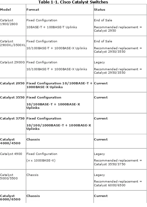
Table 1-1. Cisco Catalyst Switches
Catalyst 2950 Fixed Configuration 10/100BASE-T +
Catalyst
8000/8500 Chassis Current
In Table 1-1, each of the Catalyst product families are listed, with the form factor and current status of each switch indicated. Each of the product families in bold are considered current
products and are recommended for deployment for new
networks or for network upgrades. All other product families are either end of sale or considered legacy products that should be purchased only for existing networks where a common platform needs to be maintained.
Each of the switches in Table 1-1 is targeted at a particular switching environment, based upon size, network traffic, and features required. One way of classifying the general role of a switch is to identify the hierarchical layer in which the switch is operating. Well-designed LAN networks can be divided into three key layers:
Access Provides access to the network for end devices, such as user PCs, servers, and printers.
Distribution Provides an aggregation point for access-layer devices and then connects directly to the core. Layer 3
switching can be applied at this point, which improves convergence and scalability and allows for the introduction of network policies.
a Layer 3 core that relies on routing for redundancy and convergence.
For many networks, a network switch can provide the functions of two layers or even the entire three. Only the very large
networks typically have distinct core, distribution, and access layers; smaller networks typically have a combined
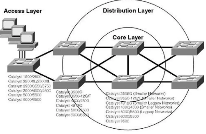
core/distribution layer and an access layer. Following the core/distribution/access layer design provides a hierarchical network that can easily scale as the network grows. Figure 1-1
illustrates the various layers of a LAN network and which platforms fit into each of the layers.
Figure 1-1. Core/Distribution/Access Layers
In Figure 1-1, notice that all of the Catalyst switches (bar the Catalyst 8500) can be used as an access layer switch. Most
use the Catalyst 5000/5500 and Catalyst 6000/6500 switch as a wiring closet switches, because they can provide very high port densities. When this happens, the high-end switch is normally providing distribution layer functionality as well.
Cisco Catalyst Switch Platforms
As described in Table 1-1, a number of Cisco Catalyst switch platforms are available, each of which are suitable for different switching environments depending on the size, complexity,
features required and of course cost. In this section, each of the Cisco Catalyst switch platforms that are available for purchase and not considered legacy switches are described (i.e., the platforms highlighted bold in Table 1-1). This includes the following switch platforms:
Catalyst 2950/3550 family
Catalyst 3550/3750
Catalyst 4000/4500
Catalyst 6000/6500
NOTE
Catalyst 2950 Family
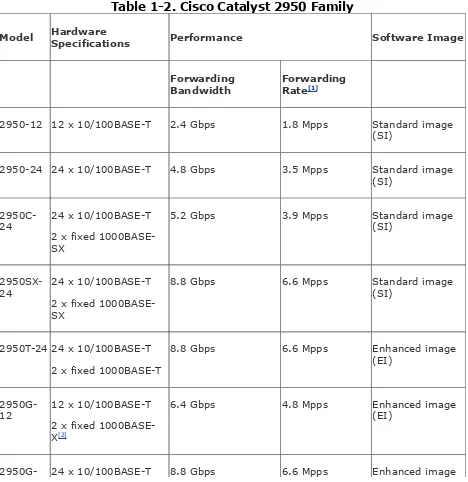
The Catalyst 2950 switches represent Cisco's entry-level switch product offering and are a fixed-configuration platform designed for access-layer/workgroup connectivity. Table 1-2 lists each of the Catalyst 2950 models and describes their hardware and software configurations. Each switch contains 8MB flash and 16MB memory.
Table 1-2. Cisco Catalyst 2950 Family
Model Hardware
Specifications Performance Software Image
Forwarding
Bandwidth ForwardingRate[1]
2950-12 12 x 10/100BASE-T 2.4 Gbps 1.8 Mpps Standard image (SI)
2950-24 24 x 10/100BASE-T 4.8 Gbps 3.5 Mpps Standard image (SI)
2950C-24 24 x 10/100BASE-T 2 x fixed 1000BASE-SX
5.2 Gbps 3.9 Mpps Standard image (SI)
2950SX-24 24 x 10/100BASE-T 2 x fixed 1000BASE-SX
8.8 Gbps 6.6 Mpps Standard image (SI)
2950T-24 24 x 10/100BASE-T 2 x fixed 1000BASE-T
8.8 Gbps 6.6 Mpps Enhanced image (EI)
2950G-12 12 x 10/100BASE-T 2 x fixed 1000BASE-X[2]
6.4 Gbps 4.8 Mpps Enhanced image (EI)
24[3]
13.6 Gbps 10.1 Mpps Enhanced Image (EI)
[1] Mpps = million packets per second, based upon a packet size of 64 bytes
[2] 1000BASE-X ports require a separate Gigabit Interface Converter (GBIC) of the appropriate Gigabit Ethernet technology (GigaStack, 1000BASE-T, 1000BASE-SX, 1000BASE-LX/LH or 1000BASE-ZX) to connect to the network.
[3] A model is available with DC power supply
As you can see from Table 1-2, many different models exist, each with different hardware and software specifications. In terms of software image, it is important to understand the difference between the standard image and enhanced image:
Standard image The standard image is a Layer 2 only image and provides traditional switching features. Standard image switches have no understanding of Layer 3/4
packets, meaning they look only at Ethernet headers and switch packets based upon those headers.
Enhanced image This image provides Layer 3/4
intelligence, allowing the switch to look deeper into frames to identify traffic generated by particular hosts and
networks, as well as the applications that have generated a frame. These capabilities provide advanced security and quality of service (QoS) features for devices and
essential for any network that runs converged voice, video, and data networks, because the switch can identify critical voice and video traffic, classify it as high priority, and then prioritize it when transmitting.
NOTE
It is important to understand that the Catalyst 2950 enhanced image does not provide Layer 3 routing capabilities, but rather the ability to understand the Layer 3 and Layer 4 properties of network traffic and apply security and/or QoS based upon those
properties.
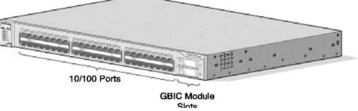
Figure 1-2 shows an example of the Catalyst 2950 switch (a Catalyst 2950G-48).
Figure 1-2. The Catalyst 2950G-48 Switch
GigaStack (WS-X3500-XL) Provides a proprietary half-duplex or full-half-duplex gigabit Ethernet connectivity. These GBICs are used to stack up to 8 Catalyst switches in a cascaded or star configuration (star configuration requires an aggregation switch such as the 3550-12G) within close physical proximity.
1000BASE-T (WS-G5483) Provides copper-based gigabit Ethernet connectivity over UTP cable up to 100 m.
1000BASE-SX (WS-G5484) Provides short range fiber-based gigabit Ethernet connectivity over multimode fiber cable up to 550 m.
1000BASE-LX/LH (WS-G5486) Provides long range fiber-based gigabit Ethernet connectivity over single-mode fiber cable up to 10 km.
1000BASE-ZX (WS-G5487) Provides extended long range fiber-based gigabit Ethernet connectivity over single-mode fiber cable up to 100 km.
NOTE
NOTE
Cisco also produces the Catalyst 2955 series of switches, which are 12-port switches with a variety of gigabit uplink options designed for industrial environments. The Catalyst 2955 ships with an industrial strength case, includes no moving parts, and ships with the enhanced software image.
Catalyst 3550 Family
The Catalyst 3550 switches represent the entry-level platform from Cisco that provides the ability to perform Layer 3
switching. Layer 3 switching is a feature that allows a switch to route traffic between different LAN segments (VLANs), without impacting performance. This allows organizations to gain the benefits of implementing a hierarchical Layer 3 routing topology in the LAN without sacrificing performance.
Cisco Catalyst 3550 switches still support traditional Layer 2 switching; in fact by default, a Catalyst 3550 operates as a Layer 2 switch. Layer 3 switching must be explicitly configured, and the features that you can configure for Layer 3 switching depend on the software image you have installed. Two software images are available when you purchase a Catalyst 3550
switch:
support other dynamic routing protocols such as Enhanced Interior Gateway Routing Protocol (EIGRP), Open Shortest Path First (OSPF), and Border Gateway Protocol (BGP). The EMI image is required for these protocols.
NOTE
Prior to Cisco IOS 12.1(13)a, the SMI image did not provide any Layer 3 switching features (i.e., static routing and RIP were not supported). With IOS 12.1(13)a and higher, Layer 3 switching using static routes and RIP is supported.
Enhanced Multilayer Image (EMI) The EMI image
provides full Layer 2 switching and Layer 3 switching, with complete support for all popular IP routing protocols,
including Routing Information Protocol (RIP), EIGRP, OSPF and BGP.
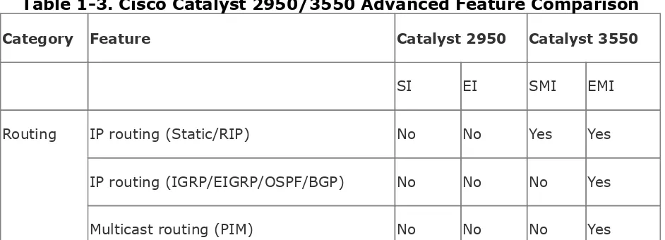
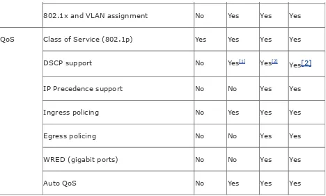
Table 1-3 provides a list of advanced features and describes there availability on the Catalyst 2950 SI and EI images, as well as the Catalyst 3550 SMI and EMI images.
Table 1-3. Cisco Catalyst 2950/3550 Advanced Feature Comparison
Category Feature Catalyst 2950 Catalyst 3550
SI EI SMI EMI Routing IP routing (Static/RIP) No No Yes Yes
Hot Standby Router Protocol (HSRP) No No No Yes Policy-based routing No No No Yes
Multi-VRF CE No No No Yes
WCCP No No No Yes
Switching Maximum MAC addresses 8000 8000 8000 12000 Maximum active VLANs 64 250 1000 1000 Maximum STP instances 64 64 128 128
ISL Trunking No No Yes Yes
IGMP Snooping Yes Yes Yes Yes
802.1s Multiple STP No Yes Yes Yes 802.1w Rapid STP No Yes Yes Yes CrossStack UplinkFast No Yes Yes Yes Gigabit EtherChannel No Yes Yes Yes Security Port-based ACLs No Yes Yes Yes
VLAN ACLs No No Yes Yes
Router ACLs No No Yes Yes
Secure Shell No Yes Yes Yes
SNMPv3 No Yes Yes Yes
802.1x and VLAN assignment No Yes Yes Yes QoS Class of Service (802.1p) Yes Yes Yes Yes
DSCP support No Yes[1] Yes[2]
Yes[2] IP Precedence support No No Yes Yes Ingress policing No Yes Yes Yes
Egress policing No No Yes Yes
WRED (gigabit ports) No No Yes Yes
Auto QoS No Yes Yes Yes
[1] Only 13 DSCP values are support
[2] All DSCP values (64 values in total) are supported
As you can see from Table 1-3, the SI for the Catalyst 2950 provides hardly any advanced switching features at all. The Catalyst 3550 SMI possesses more features than the Catalyst 2950 EI, and the Catalyst 3550 EMI provides all features listed in Table 1-3.
Table 1-4 lists each of the Catalyst 3550 models and describes there hardware and software configuration. Each switch
contains 16 MB flash and 64 MB memory.
Table 1-4. Cisco Catalyst 3550 Models
Forwarding
3550-24[2]24 x 10/100BASE-T 2 x 1000BASE-X
8.8 Gbps 6.6 Mpps SMI or EMI
3550-24PWR 24 x inline powered10/100BASE-T 2 x 1000BASE-X
8.8 Gbps 6.6 Mpps SMI or EMI
3550-48 48 x 10/100BASE-T 2 x 1000BASE-X
13.6 Gbps 10.1 Mpps SMI or EMI
3550-12T 10 x 10/100/1000BASE-T 2 x 1000BASE-X
24 Gbps 17.0 Mpps EMI only
3550-12G 10 x 1000BASE-X
2 x 10/100/1000BASE-T
24 Gbps 17.0 Mpps EMI only
[1] Mpps = million packets per second, based upon a packet size of 64 bytes
[2] A model is available with DC power supply
Figure 1-3. The Catalyst 3550-48 Switch
Figure 1-4. The Catalyst 3550-12T Switch
The GBIC options for 1000BASE-X ports on the Catalyst 3550 switches are the same as for the Catalyst 2950.
Catalyst 3750 Family
1000BASE-X ports in a single 1.5RU chassis. The Catalyst 3750 is similar in many respects to the Catalyst 3550, with the same concept of SMI and EMI and full Layer 3 switching capabilities. It also provides several enhancements over the Catalyst 3550, which include the following:
Memory The Catalyst 3750 includes 128 MB memory (compared with 64 MB in Catalyst 3550), which allows for more unicast and multicast routes to be stored in the
routing table.
Gigabit Ethernet over copper High-density 10/100/1000 gigabit Ethernet copper ports.
IP version 6 (IPv6) Support for hardware-based Layer 3 switching for IPv6 in future software releases.
Stackwise technology Enhances performance, scalability, and management by allowing up to 9 switches to be
stacked using a 32-Gbps interconnect. All switches are managed as a single entity, with all ports from all switches appearing as part of a single virtual switch.
Jumbo frames Allows the 3750 to support oversized Ethernet frames on Gigabit Ethernet ports, which are important for high data transfer applications such as storage and video.
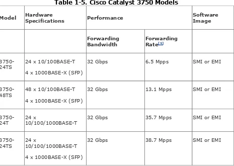
Table 1-5 lists each of the Catalyst 3750 switches. Each switch contains 16 MB flash and 128 MB memory.
Table 1-5. Cisco Catalyst 3750 Models
Model HardwareSpecifications Performance SoftwareImage
Forwarding
Bandwidth ForwardingRate[1]
3750-24TS 24 x 10/100BASE-T 4 x 1000BASE-X (SFP)
32 Gbps 6.5 Mpps SMI or EMI
3750-48TS 48 x 10/100BASE-T 4 x 1000BASE-X (SFP)
32 Gbps 13.1 Mpps SMI or EMI
3750-24T 24 x10/100/1000BASE-T 32 Gbps 35.7 Mpps SMI or EMI
3750-24TS 24 x10/100/1000BASE-T 4 x 1000BASE-X (SFP)
32 Gbps 38.7 Mpps SMI or EMI
[1] Mpps = million packets per second, based upon a packet size of 64 bytes
Catalyst 4000/4500 Family
The Catalyst 4000/4500 switch family represents the entry-level chassis-based switch offering from Cisco. The Catalyst
4000/4500 switches are made up of three basic components:
and fans.
Supervisor engine This includes the switch processor and switching engine and is required to operate the switch.
Switching modules These provide ports for connecting various types of devices to the switch.
Each of these components are now discussed.
Catalyst 4000/4500 Chassis
The chassis provided by the Catalyst 4000/4500 series switches vary across the Catalyst 4000 and Catalyst 4500 family. The major difference between the Catalyst 4000 series chassis and Catalyst 4500 series chassis is power; the Catalyst 4500 has an improved power distribution system that is capable of
supporting inline power (i.e., the ability to power phones and wireless access points over Ethernet cabling) without requiring an external power shelf (as is required with the Catalyst 4000). The Catalyst 4500 series also provides a chassis that allows for redundant supervisor engines, whereas the Catalyst 4000 series chassis do not provide this.
Within the Catalyst 4000 series, two chassis are provided:
Catalyst 4003 3-slot chassis that provides one supervisor slot and two data slots.
Catalyst 4006 6-slot chassis that provides one supervisor slot and five data slots.
Catalyst 4503 3-slot chassis that provides one supervisor slot and two data slots.
Catalyst 4506 6-slot chassis that provides one supervisor slot and five data slots.
Catalyst 4507R 7-slot chassis that provides two supervisor slots (one for redundancy) and five data slots.
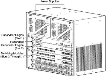
Figure 1-5 and Figure 1-6 shows examples of the Catalyst 4000 and 4500 chassis (the Catalyst 4006 and 4507R).
Figure 1-5. The Catalyst 4006 Chassis
It is important to note that the Catalyst 2948G and Catalyst 2980G switches are essentially fixed configuration Catalyst 4000 switches with a Supervisor engine, power supply and a fixed configuration of 48 * 10/100BASE-T + 2 * 1000BASE-X ports (2948G) or 80 * 10/100BASE-T + 2 * 1000BASE-X ports (2980G). Figure 1-7 shows the Catalyst 2980G switch.
Supervisor Engines
The Catalyst 4000/4500 switch family consists of four
Supervisor engines, which each vary in internal architecture, functionality, and operating system used for switch
management. Table 1-6 describes each of the Catalyst 4000/4500 supervisors
Table 1-6. Cisco Catalyst 4000/4500 Supervisor Engines
Supervisor Supported
Chassis Performance OperatingSystem
Forwarding
Bandwidth ForwardingRate[1]
Supervisor
1 4003 24 Gbps 18 Mpps CatOS
Supervisor
2 4006
4503 4506
64 Gbps[2] 18 Mpps CatOS
Supervisor
[2] Forwarding bandwidth is 28 Gbps in Catalyst 4503
[3] The same forwarding rate applies for Layer 2 and Layer 3 switched traffic
The Supervisor 1 and Supervisor 2 engines are Layer 2
switching only supervisors and are managed using the CatOS operating system. It is important to note that the Supervisor 2 contains a blocking architecture internally, meaning congestion is possible in certain configurations internally on the Supervisor.
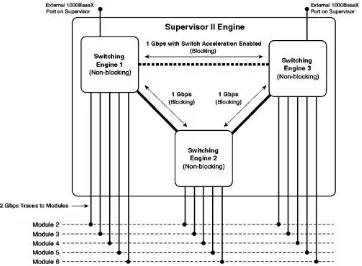
Figure 1-8 shows the internal blocking architecture of the Supervisor 2 switch.
Figure 1-8. Internal Architecture of Supervisor 2
Switch
The Supervisor 1 is non-blocking, because it contains only a single 24-Gbps non-blocking
switching engine that provides each of the 2-Gbps traces to module 2 and module 3 in the Catalyst 4003.
In Figure 1-8, notice that three separate switching engines (SEs) exist (each provide 24-Gbps internal non-blocking forwarding bandwidth), with each providing a 2-Gbps
full-duplex trace to each module in the chassis (providing a total of 3 * 2-Gbps or 6-Gbps full-duplex bandwidth to each module).
Be careful of the "marketing terms" using by Cisco and other switch vendors to provide forwarding bandwidth performance figures. The quoted performance figures always refer to the total system bandwidth and not to the full-duplex bandwidth provided. For example, a 1-Gbps full-duplex connection is considered to provide a total of 2-Gbps bandwidth (1 Gbps in one direction, 1 Gbps in the other direction). In the case of SE1 and SE3 on a Catalyst 4000 Supervisor 2, each SE has 5 * 2-Gbps full-duplex connections to each line card, a single external 1-Gbps full-duplex 1000BASE-X connection on the supervisor and a 1-Gbps full-duplex connection to SE2. This provides a total of 12 Gbps full-duplex bandwidth (5 * 2 + 1 + 1), or a total forwarding bandwidth of 24 Gbps.
Although each SE is non-blocking internally, a single 1-Gbps full-duplex connection interconnects the switching engines, which potentially causes blocking (congestion) on the
interconnections between each SE if devices attached to one switching engine are communicating with devices attached to another switching engine.
If you are not using the two external 1000BASE-X ports on the Supervisor 2 module, you can disable them by configuring switch acceleration and
introduce a third 1-Gbps interconnection between SE1 and SE3, reducing the amount of potential blocking (see dashed connection between SE1 and SE3 in Figure 1-8). You can also purchase a
backplane channel module for the Supervisor 2, which doubles the bandwidth between each switching engine from 1 Gbps to 2 Gbps.
The Supervisor 3 and Supervisor 4 engines are Layer 2 and
Layer 3 switching capable and are managed using the Cisco IOS operating system. These supervisors are completely
non-blocking internally, unlike the Supervisor 1 and Supervisor 2, consisting essentially of one large non-blocking switching
engine to which each module trace connects to. Just as for the Catalyst 3550/3750 switches, a basic image provides Layer 3 switching using static and RIP routing, whilst a separate
enhanced image provides full Layer 3 switching using static, RIP, IGRP, EIGRP, OSPF, and BGP routing.
NOTE
The differences between the Supervisor 3 and
Switching Modules
The Catalyst 4000/4500 switch family provides for a wide variety of switching modules, allowing for high-density 10/100BASE-T, 10/100/1000BASE-T, and 1000BASE-X deployments. Other modules supported include a Layer 3
routing module (for Supervisor 1/2 deployment, not supported in Supervisor 3/4) and an access gateway module (provides voice gateway functionality). Table 1-7 lists some of the switching modules available for the Catalyst 4000/4500.
Table 1-7. Cisco Catalyst 4000/4500 Switching Modules
Module Part Number Description
WS-X4148-RJ 48 x 10/100BASE-T RJ-45 ports
WS-X4148-RJ45V 48 x inline powered 10/100BASE-T RJ-45 ports
WS-X4148-RJ21 48 x 10/100BASE-T ports with RJ-21 Telco connectors WS-X4232-GB-RJ 32 x 10/100BASE-T + 2 x 1000BASE-X
WS-X4232-L3 Layer 3 Router module
32 x 10/100BASE-T and 2 x 1000BASE-X ports WS-X4424-GB-RJ45 24 x 10/100/1000BASE-T
WS-X4448-GB-RJ45 48 x 10/100/1000BASE-T WS-X4448-GB-LX 48 x 1000BASE-LX
Catalyst 6000/6500 Family
The Catalyst 6000/6500 family represents the flagship of the Cisco Catalyst switching product range. The switch is aimed at the enterprise network and also at service provider networks. The Catalyst 6000/6500 is chassis-based, which means that it consists of the same fundamental components as a Catalyst 4000/4500 switch (i.e., chassis, supervisor engine, and
switching modules), which are now discussed in more detail.
Catalyst 6000/6500 Chassis
The chassis provided by the Catalyst 6000/6500 series switches vary across the Catalyst 6000 and Catalyst 6500 family. The differences between the Catalyst 6000 series chassis and Catalyst 6500 series are listed below:
Backplane Both the Catalyst 6000 and Catalyst 6500
contain a shared 32-Gbps backplane; however, the Catalyst 6500 also supports an upgrade to a 256-Gbps crossbar switching matrix by adding an optional switch fabric module.
Scalability The Catalyst 6000 is provided only in a 6-slot chassis (6006) and 9-slot (6009) chassis, while the 6500 provides 3-slot (6503), 6-slot (6506), 9-slot (6509), and 13-slot (6513) chassis options.
Figure 1-9. The Catalyst 6006 Chassis
Supervisor Engines
The Catalyst 6000/6500 switch family consists of three
Supervisor engines, which each vary in terms of functionality and performance:
Supervisor 2 Provides support for advanced security and QoS features, as well as CEF-based (Cisco Express
Forwarding) Layer 3 switching. The Supervisor 2 also supports the switch fabric module (SFM), which increases backplane capacity from 32 Gbps to 256 Gbps and supports a Layer 2/Layer 3 forwarding rate of up to 210 Mpps.
Supervisor 720 Provides support for advanced security and QoS features, as well as advanced CEF-based Layer 3 switching. The Layer 3 switching engine supports IPv6 routing, network address translation, GRE tunneling, and MPLS all in hardware. The Supervisor 720 includes a crossbar switching matrix (formerly provided via the
separate SFM in conjunction with the Supervisor 2), which provides a backplane capacity of 720 Gbps and a Layer
2/Layer 3 forwarding rate of up to 200 Mpps (IPv6) and 400 Mpps (IPv4). The Supervisor 720 also includes PFC3 and MSFC3 daughter cards (discussed later), which provide the Layer 3 switching capabilities of the Supervisor.
All supervisors can be installed in redundant pairs, ensuring maximum availability in the event of an active supervisor failure. Any additional add-on modules that extend system
performance or functionality (e.g., SFM, PFC daughter card, and MSFC daughter card) can also be installed in a redundant
configuration, ensuring the highest levels of availability
You have learned that the Supervisor 2 engine supports the SFM; each Supervisor also supports two types of add-on modules onboard the Supervisor itself (i.e., daughter cards), which extend the functionality and performance of the
supervisor engine to provide the features and performance described above. These daughter cards are described as follows:
intelligence, allowing for advanced security and QoS
features to be applied based upon the Layer 3 and Layer 4 parameters of traffic. The PFC also provides the hardware forwarding engine when Layer 3 switching is enabled with the addition of an MSFC. The PFC can be installed just by itself, without the MSFC (discussed next).
Multilayer switching feature card (MSFC) The MSFC is essentially a router on a daughter card, providing full Layer 3 routing functionality and enabling the Catalyst 6000/6500 to perform Layer 3 switching. In a Layer 3 switching
configuration, the MSFC provides the control plane
component of L3 switching (i.e., populating and maintaining the routing table), while the PFC provides the data plane component of L3 switching (i.e., rewriting frame and packet headers and switching routed packets to the appropriate egress port), which means you must have a PFC installed before installing an MSFC. The MSFC also allows the switch to operate in native IOS, where the Supervisor and MSFC are managed via a single Cisco IOS-based management interface, integrating Layer 2 and Layer 3 switching
management (similar to the Catalyst 3550 EMI and Catalyst 4000/4500 Supervisor 3/4).
NOTE
Without a MSFC, the Catalyst 6000/6500 Supervisor engines operate the CatOS operating system. When you add a MSFC, by default, the Supervisor still runs CatOS and the MSFC runs Cisco IOS (this
configuration is known as referred to as hybrid IOS). You can then configure the switch to operate in
native IOS mode, where the Supervisor and MSFC are managed by the same Cisco IOS management interface, as long as the switch has an MSFC
There are three generations of PFC and MSFC modules, with various combinations of Supervisor engines and different versions of PFC and MSFC modules making it a reasonably complex task to understand which features are supported in each configuration. Chapter 6, "Layer 3 Switching," discusses the features of the various Supervisor, PFC, and MSFC
configurations in more detail.
Switching Modules
On the Catalyst 6000/6500, you can purchase three types of line cards:
Classic A classic module connects to the 32-Gbps shared backplane only.
Fabric-enabled A fabric-enabled module connects to both the 32-Gbps backplane and also has an 8-Gbps full-duplex connection to the 256-Gbps crossbar switch matrix
(requires Supervisor 720 or switch fabric module installed).
Fabric-only Connects only to the 256-Gbps crossbar switch matrix via dual 8-Gbps full-duplex connections (requires Supervisor 720 or switch fabric module installed).
Even though there are three types of modules, all modules can communicate with each other, even if they are attached to different switching backplanes (e.g., classic and fabric-only cards are not connected to the same bus). In this situation, an interconnection between the crossbar switching matrix is
some of the LAN switching modules available for the Catalyst 6000/6500.
Table 1-8. Cisco Catalyst 6000/6500 Switching Modules
Module Part Number Description
WS-X6148-RJ-45 48 x 10/100BASE-T RJ-45 ports
WS-X6148-RJ-45V 48 x inline powered 10/100BASE-T RJ-45 ports WS-X6148-RJ-21 48 x 10/100BASE-T with RJ-21 Telco connectors WS-X6348-RJ-45 48 x 10/100BASE-T RJ-45 ports (Enhanced QoS)
WS-X6348-RJ-45V 48 x inline powered 10/100BASE-T RJ-45 ports (Enhanced QoS) WS-X6348-RJ-21 48 x 10/100BASE-T with RJ-21 Telco connectors (Enhanced QoS) WS-X6548-RJ-45 48 x 10/100BASE-T RJ-45 ports (Fabric enabled)
WS-X6548-RJ-45V 48 x inline powered 10/100BASE-T RJ-45 ports (Fabric enabled) WS-X6548-RJ-21 48 x 10/100BASE-T with RJ-21 Telco connectors (Fabric enabled) WS-X6408A-GBIC 8 x 1000BASE-X
WS-X6416-GBIC 16 x 1000BASE-X WS-X6316-GE-TX 16 x 1000BASE-T
WS-X6516-GE-TX 16 x 1000BASE-T (Fabric enabled)
outside the bounds of pure LAN switching and Layer 3 switching. The Catalyst 6000/6500 not only provides LAN
switching modules, which allow for high-density 10/100BASE-T, 10/100/1000BASE-T, and 1000BASE-X deployments, but also provides a wide range of other modules called services modules
that extend and enhance the functionality of the Catalyst 6000/6500. The following lists some examples of the services modules available for the Catalyst 6000/6500 switch:
Firewall services module (WS-SVC-FWM-1-K9)
Essentially a PIX firewall on steroids, this module provides up to 5 Gbps firewall throughput, ensuring advanced
security features can be implemented in the network without compromising performance.
IPSec virtual private network (VPN) services module (WS-SVC-IPSEC-1) Provides up to 1.9 Gbps of triple DES VPN performance, ensuring private data can be protected without comprising performance.
Intrusion detection system module (WS-SVC-IDS2BUNK9), also known as IDSM) Analyzes traffic from multiple VLANs for intrusive activity that might
indicate an attack against the network, generating alarms and configuring security devices to block attacks. The latest IDSM can analyze up to 600 Mbps of traffic.
Content switching module (WS-SVC-CSG-1) Provides intelligent application-layer load balancing for web server farms and other application server farms, providing
enhanced performance, availability, and scalability.
As you can see from the preceding, the Catalyst 6000/6500 is not just a LAN switch; it is a platform that can integrate LAN switching features with advanced security, application, and network management features.
Catalyst Operating Systems
Today there are two main operating systems that are used on Cisco Catalyst switches:
Catalyst Operating System (CatOS)
Cisco Internetwork Operating System (Cisco IOS)
You are most likely familiar with Cisco IOS; Cisco IOS is the popular operating system installed on nearly all Cisco routers and is a very mature, feature-rich, and extensible operating system that offers Cisco customers significant value-add and return on investment. Historically, Cisco acquired a few major switch vendors in the early- to mid-1990s, which resulted in the introduction of what is now known as CatOS. CatOS is used to operate the following platforms:
Catalyst 2900/4000/4500 with Supervisor 1/2
Catalyst 5000/5500
Catalyst 6000/6500
NOTE
The ability to perform bulk administration tasks has been addressed in later releases of Cisco IOS.
Unlike Cisco IOS, which has many configuration modes and different commands, CatOS provides three basic types of commands:
set These commands apply some configuration to the switch. For example, the set system name command is used to configure the switch name.
clear These commands remove some configuration from the switch.
show These commands display configuration status information, which allows you to verify the operational configuration.
Other commands are used for system management, such as
copy and write; however, for configuration tasks, you will only ever use the set and clear commands and then use show
commands to verify your configuration.
NOTE
Many chassis-based CatOS switches support optional Layer 3 routing modules (e.g., Catalyst 5000/5500 RSM, Catalyst 6000/6500 MSFC), which include their own Cisco IOS. This means that the module
and network connectivity, with management of the module performed separately from the Supervisor that runs the switch. When CatOS is used to manage the Layer 2 switching component, and Cisco IOS is used to manage the Layer 3 routing component, the switch is said to be managed using hybrid IOS,
because two different operating systems (CatOS and Cisco IOS) are used to manage the switch.
Cisco plans to eventually phase out CatOS, moving all switching platforms to Cisco IOS, which will allow for a uniform
management interface across all Cisco switches and routers, as well as better integration of Cisco switching and routing
features. Today, the following platforms are based upon Cisco IOS:
Catalyst 2900XL/3500XL
Catalyst 2950/3550/3750
Catalyst 4000/4500 Supervisor 3/4
Catalyst 6000/6500 with MSFC running native IOS
As you can see from the preceding list, the Catalyst 4000/4500 and Catalyst 6000/6500 switches can either run CatOS or Cisco IOS, which leads to the question: Which operating system
should I run? On the Catalyst 4000/4500, the operating system is tied to the type of Supervisor engine, and normally the much higher performance capabilities and integrated Layer 3
however, that many features are still present in CatOS that are not present in Cisco IOS and that many new features are first released into CatOS code before Cisco IOS. This applies also to the Catalyst 6000/6500, where you can use either CatOS or Cisco IOS regardless of the Supervisor engine installed.
NOTE
Although CatOS still leads the development efforts in terms of new features over comparative Cisco IOS features, Cisco has indicated that this is short lived, with a goal of introducing feature parity and then focusing on the development of new features on Cisco IOS.
Although Cisco IOS might be the way of the future, for now and many years to come, there still exists a large deployment of CatOS-based switches. This means you must ideally be