Table of Contents:
Chapter 1. IPv6 Versus IPv4 ………..………… page 4 Section 1.1. The History of IPv6
Section 1.2. Overview of Functionality Section 1.3. Transition Aspects
Section 1.4. IPv6 Alive
Chapter 2. The Structure of the IPv6 Protocol ………..……… page 11 Section 2.1. General Header Structure
Section 2.2. The Fields in the IPv6 Header Section 2.3. Extension Headers
Chapter 3. IPv6 Addressing ………..…… page 24 Section 3.1. Address Types
Section 3.2. Address Notation Section 3.3. Prefix Notation Section 3.4. Format Prefixes Section 3.5. Address Privacy
Section 3.6. Aggregatable Global Unicast Address Section 3.7. Anycast Address
Section 3.8. Multicast Address Section 3.9. Required Addresses
Chapter 4. ICMPv6 ……… page 38 Section 4.1. General Message Format
Section 4.2. ICMP Error Messages
Section 4.3. ICMP Informational Messages Section 4.4. Processing Rules
Section 4.5. The ICMPv6 Header in a Trace File Section 4.6. Neighbor Discovery
Section 4.7. Autoconfiguration Section 4.8. Path MTU Discovery
Section 4.9. Multicast Group Management
Chapter 5. Security in IPv6 ……… page 61 Section 5.1. Types of Threats
Section 5.2. Basic Security Requirements and Techniques Section 5.3. Security in the Current Internet Environment Section 5.4. Current Solutions
Section 5.5. Open Security Issues in the Current Internet Section 5.6. The IPSEC Framework
Section 5.7. IPv6 Security Elements
Section 5.8. Security Association Negotiation and Key Management Section 5.9. Interworking of IPv6 Security with Other Services Section 5.10. Open Issues in IPv6 Security
Chapter 6. Quality of Service in IPv6 ……….……… page 80 Section 6.1. QoS Paradigms
Section 6.2. Quality of Service in IPv6 Protocols Section 6.3. QoS Architectures
Chapter 7. Networking Aspects ……… page 89 Section 7.1. Layer 2 Support for IPv6
Section 7.2. Multicasting Section 7.3. Mobile IP
Section 7.4. Network Designs
Chapter 8. Routing Protocols ……….……… page 100 Section 8.1. RIPng
Section 8.2. OSPF for IPv6 (OSPFv3) Section 8.3. BGP Extensions for IPv6
Section 8.4. Other Routing Protocols for IPv6
Chapter 9. Upper-Layer Protocols ……… page 157 Section 9.1. UDP/TCP
Section 9.2. DHCP Section 9.3. DNS Section 9.4. SLP Section 9.5. FTP Section 9.6. Telnet Section 9.7. Web Servers
Chapter 10. Interoperability ………..……… page 169 Section 10.1. Dual-Stack Techniques
Section 10.2. Tunneling Techniques
Section 10.3. Network Address and Protocol Translation Section 10.4. Comparison
Section 10.5. Vendor Support
Chapter 11. Get Your Hands Dirty ……… page 190 Section 11.1. Sun Solaris
Section 11.2. Linux Section 11.3. Microsoft Section 11.4. Applications Section 11.5. Cisco Router
Section 11.6. Description of the Tests Section 11.7. Vendor Support
Appendix A. RFCs ……… page 208 Section A.1. Standards
Appendix B. IPv6 Resources ………...………...……… page 212 Section B.1. Ethertype Field
Section B.2. Next Header Field Values (Chapter 2)
Section B.3. Reserved Anycast IDs (Chapter 3,RFC 2526)
Chapter 1
. IPv6
Versus IPv4
IPv6 is sometimes called the Next Generation Internet Protocol, or IPng. Even though the Internet is seen as a relatively new technology, the protocols and technologies that make it work were developed in the 1970s and 1980s. The current Internet and all our corporate and private intranets use IPv4. Now, with IPv6, the first major upgrade of the Internet protocol suite is on the horizon or maybe even closer. Close enough, anyway, to start taking it seriously.
1.1 The History of IPv6
The effort to develop a successor protocol to IPv4 was started in the early 1990s by the Internet Engineering Task Force (IETF). Several parallel efforts began simultaneously, all trying to solve the foreseen address space limitation as well as provide additional functionality. The IETF started the IPng area in 1993 to investigate the different proposals and to make recommendations for further procedures.
The IPng area directors of the IETF recommended the creation of IPv6 at the Toronto IETF meeting in 1994. Their recommendation is specified in RFC 1752, "The Recommendation for the IP Next Generation Protocol." The Directors formed an Address Lifetime Expectation (ALE) working group, whose job was to determine whether the expected lifetime for IPv4 would allow the development of a protocol with new functionality or if the remaining time would only allow for developing an address space solution. In 1994, the ALE working group projected the IPv4 address exhaustion to occur sometime between 2005 and 2011, based on the statistics that were available at that time.
For those of you who are interested in the different proposals, here's some more information about it (from RFC 1752). There were four main proposals called CNAT, IP Encaps, Nimrod, and Simple CLNP. Three more proposals followed: the P Internet Protocol (PIP), the Simple Internet Protocol (SIP), and TP/IX. After the March 1992 San Diego IETF meeting, Simple CLNP evolved into TCP and UDP with Bigger Addresses (TUBA) and IP Encaps evolved into IP Address Encapsulation (IPAE). IPAE merged with PIP and SIP and called itself Simple Internet Protocol Plus (SIPP). The TP/IX working group changed its name to Common Architecture for the Internet (CATNIP). The main proposals were now CATNIP, TUBA, and SIPP. For a short discussion of the proposals, refer to RFC 1752.
CATNIP is specified in RFC 1707, TUBA in RFC 1347, RFC 1526, and RFC 1561, and SIPP in RFC 1710.
The Internet Engineering Steering Group approved the IPv6 recommendation and drafted a Proposed Standard on November 17, 1994. The core set of IPv6 protocols became an IETF Draft Standard on August 10, 1998.
Why is the new protocol not IPv5? The version number 5 could not be used because it had been allocated to an experimental stream protocol.
1.2 Overview of Functionality
interoperable with the current IPv4. IPv6 is designed to run well on high performance networks like Gigabit Ethernet, ATM, and others, as well as low bandwidth networks (e.g., wireless). In addition, it provides a platform for new Internet functionality that will be required in the near future, such as extended addressing, better security, and quality of service (QoS) features.
IPv6 includes transition and interoperability mechanisms that are designed to allow users to adopt and deploy IPv6 step by step as needed and to provide direct interoperability between IPv4 and IPv6 hosts. The transition to a new version of the Internet Protocol (IP) must be incremental, with few or no critical interdependencies, if it is to succeed. The IPv6 transition allows users to upgrade their hosts to IPv6 and network operators to deploy IPv6 in routers with very little coordination between the two groups.
The main changes from IPv4 to IPv6 can be summarized as follows:
Expanded addressing capability and autoconfiguration mechanisms
The address size for IPv6 has been increased to 128 bits. This solves the problem of the limited address space of IPv4 and offers a deeper addressing hierarchy and simpler configuration. There will come a day when you will hardly remember how it felt to have only 32 bits in an IP address. Network administrators will love the autoconfiguration mechanisms built into the protocol. Multicast routing has been improved, with the multicast address being extended by a scope field. And a new address type has been introduced, called Anycast address, which can send a message to the nearest single member of a group.
Simplification of the header format
The IPv6 header has a fixed length of 40 bytes. This actually accommodates only an 8-byte header plus two 16-byte IP addresses (source and destination address). Some fields of the IPv4 header have been removed or become optional. This way, packets can be handled faster with lower processing costs.
Improved support for extensions and options
With IPv4, options were integrated into the basic IPv4 header. With IPv6, they are handled as Extension headers. Extension headers are optional and only inserted between the IPv6 header and the payload, if necessary. This way the IPv6 packet can be built very flexible and streamlined. Forwarding IPv6 packets is much more efficient. New options that will be defined in the future can be integrated easily.
Extensions for authentication and privacy
1.3 Transition Aspects
Is IPv6 worth all the migration and upgrade headaches? Will it ever become the IP of the future? Can't IPv4 extensions offer all that functionality? After all, we have Network Address Translation (NAT) to solve address space problems and IPSEC to provide security.
The 128-bit address space is the most obvious feature of the new protocol, but it is not the only important change. The IPv6 package includes important features such as higher scalability, better data integrity, QoS features, autoconfiguration mechanisms that make it manageable even for high numbers of dynamically connecting devices, improved routing aggregation in the backbone, and improved multicast routing.
Extensions for IPv4 that have been widely deployed, such as NAT, should be viewed as good solutions but only for limited short-term scenarios. In the long term, nothing can replace IPv6's features for inherent secure end-to-end connectivity. Multimedia and interactive, transaction-oriented network applications require high levels of connectivity that can only be provided by IPv6. In the future, an unforeseeable number of new devices may want to connect to our networks, including devices such as Personal Digital Assistants (PDAs), mobile phones, smart set-top boxes with integrated web browsers, home entertainment systems, coffee machines, refrigerators, and car devices. The list is endless. Only IPv6, with its extended address space and advanced autoconfiguration and mobility features, can manage such devices. There is no comparable alternative technology in sight.
1.4 IPv6 Alive
There are already a surprising number of global test networks and even commercial networks running over IPv6. I discuss some interesting examples in the next sections. In order to describe what they are doing, I use some IPv6-specific terms that are probably not familiar to you yet. They are all explained in this book.
In February 2002 over 120 production networks have been allocated IPv6 address
prefixes. For a current list, refer to
http://www.dfn.de/service/ipv6/ipv6aggis.html.
1.4.1 The 6Bone
The 6Bone started out as a network of IPv6 islands working over the existing IPv4 infrastructure of the Internet by tunneling IPv6 packets in IPv4 packets. The tunnels were mainly statically configured point-to-point links. The 6Bone became a reality in early 1996 as a result of an initiative of several research institutes. The first tunnels were established between the IPv6 laboratories of G6 in France, UNI-C in Denmark, and WIDE in Japan.
1.4.1.1 Structure of the 6Bone
The 6Bone is structured as a hierarchical network of two or more layers. The top layer consists of a set of backbone transit providers, called pseudo Top Level Aggregators (pTLAs), which use BGP4+ as a routing protocol. The bottom layer is comprised of leaf sites connected via the 6Bone. Zero or more intermediate layers, called pseudo Next Level Aggregators (pNLAs), interconnect leaf sites and the pTLA backbone networks.
1.4.1.2 Addressing
are currently allocated 32-bit prefixes (previously, 24- and 28-bit prefixes were allocated) that must be administered according to the rules defined for pTLAs. So every pTLA plays the role of an experimental top-level ISP and assigns chunks of its addressing space to directly connected transit and leaf sites without breaking aggregation inside the 6Bone backbone.
1.4.1.3 Growth
The 6Bone is growing fast. In December 1997 there were 43 backbone sites and 203 leaf sites registered. In December 1998 there were 51 backbone sites and 332 leaf sites. In January 2000 there were 67 backbone sites and 505 leaf sites.
I gave up on trying to find a nice picture of the world with the 6Bone backbone sites on it. The 6Bone has grown too big to display it in one screenshot. If you want to get a feeling for the size and workings of the 6Bone, go to http://www.cs-ipv6.lancs.ac.uk/ipv6/6Boneand look at the maps, statistics, and tools.
At the time of this writing, the number of nodes in the 6Bone has just reached 1000 nodes and grows daily. Find an updated list at http://www.cs-ipv6.lancs.ac.uk/ipv6/6Bone/Whois/index.html#full.
1.4.1.4 Joining the 6Bone
Membership in the 6Bone is open to anyone. Reasons for joining, besides the fun of it, would be to gain early experience working with IPv6, to build the expertise necessary to make decisions about when and how to use IPv6 for production networks, and to have working access to IPv6 servers and resources. Joining the 6Bone connects you with a cool crowd of people who want to be on top of technology and are willing to share their experience.
The 6Bone community spans the globe and is very active and enthusiastic. By joining, you not only gain access to the network and the common experience of those in it; you can also participate and help develop protocols, programs, and procedures.
If you are interested in joining the 6Bone, here's the link:
http://www.6bone.net/6bone_hookup.html.
There are different ways for you to connect to either the 6Bone or production IPv6 networks:
• Become an end site of an existing 6Bone ISP (which means you will get your 48-bit IPv6 external routing prefix from that ISP's TLA). You can also get temporary address allocations from tunnel broker sites (see the 6Bone home page for more information).
• Apply for your own 6Bone TLA (if you are an ISP) based on the 6Bone process.
Obviously you need an entry point into the 6Bone. Try to find one that is close to your normal IPv4 path into the Internet. You can find a good 6Bone TLA on the 6Bone home page at
http://www.6bone.net/6bone_pTLA_list.html. Use traceroute to determine the closest path.
1.4.2 IPv6 Commercial Networks
Since I started writing this book, a lot has happened in the development of IPv6. There are many production networks worldwide that have already been assigned IPv6 address prefixes. We picked four examples of companies that made their step into the future by offering IPv6 services.
1.4.2.1 vBNS+
vBNS+ is a specialized US IP network that supports high-performance, high-bandwidth applications. The vBNS+ network supports both native IPv6-over-ATM connections and tunneled IPv6-in-IPv4 connections. The vBNS+ service has been assigned its own sTLA from ARIN, as well as a pTLA for the 6Bone, and is delegating address space under these assignments to vBNS-attached sites. For more information, refer to their site at http://www.vbns.net.
1.4.2.2 Telia Sweden
In summer 2001, Telia, in Sweden, announced its intention to build a new generation Internet based on IPv6. By the end of 2001, connection points were installed in Stockholm, Farsta, Malmoe, Gothenburg (Sweden), Vasa (Finland), Oslo, Copenhagen, and London.
I spoke with the project manager at Telia because I thought that his early adopter input might be interesting for companies that consider going into IPv6. Telia's intent was to break through the lethargy of the chicken and the egg problem: vendors do not develop because the market is not asking for it, and the market doesn't ask for it because vendors don't develop. So Telia made the decision to create a market by building an IPv6 network and opening it to the public. Telia's hope is that, through the publicity of its endeavor, other companies will follow suit, and the acceptance and development of IPv6 will increase.
At the current stage of its rollout, Telia is keeping the IPv6 network separate from the existing IPv4 infrastructure. There were different reasons for this decision:
• It was easier to start by keeping the networks separate. Telia does not have to educate all of its IPv4 engineers to use IPv6 overnight.
• If there are problems with the IPv6 network, the IPv4 network is not affected in any way.
• It is less complex to configure if the networks are separate.
The new network is primarily built as a native IPv6 network. In some instances, tunnels over IPv4 are used. Currently, Telia is offering an IPv6 transport service to a limited number of customers. It will add features and gradually open the IPv6 network as a general service for everyone. Telia uses Hitachi routers that support IPv6 in hardware (versus software implementations).
After rolling out the first connection points, Telia concluded that market support for IPv6 was sufficient to get started. There are applications that will need to be ported to IPv6, but Telia recommends that companies and ISPs start right away. The foundation is here and when IPv6 is implemented on a broader range, vendors and application developers will be encouraged to speed up development.
1.4.2.3 Internet Initiative Japan
networks. In December 2001 IIJ extended its IPv6 services to individual users connecting through IIJmio DSL/SF, an ADSL Internet service.
For information about IIJ's services, refer to http://www.iij.ad.jp/IPv6/index-e.html.
1.4.2.4 NTT Communications Corporation
NTT Laboratories started one of the largest global IPv6 research networks in 1996. Trials of their global IPv6 network, using official IPv6 addresses, began in December 1999. Since spring 2001, NTT Communications has offered commercial IPv6 services.
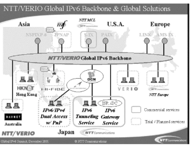
In April 2001 the company started their commercial IPv6 Gateway Service. This native IPv6 backbone service connects sites in Japan to the NTT/VERIO Global Tier1 IPv6 backbone deployed over Asia, the U.S., and Europe. Monitoring and operation continues 7 days a week, 24 hours a day, through NTT Communications NOC in Tokyo, Japan and Verio NOC in Dallas, US. Figure 1-1shows the layout of the backbone.
Figure 1-1. NTT/VERIO's global IPv6 backbone
polling in commercial operational tools. They utilize their own custom-developed router configuration tools and network management tools that support IPv6.
NTT offers Points Of Presence (POPs) all over the world, currently in London, Palo Alto, San Jose, Seattle, and Tokyo. They plan to extend their services throughout the world; the next POPs will be in Hong Kong and Australia. NTT's services include official IPv6 addresses from their sTLA block, IPv6 Internet connectivity, and DNS reverse zone delegation for the subscriber's IPv6 address space.
For an overview of NTT's global IPv6 services and how you can participate and connect, refer to http://www.v6.ntt.net/globe/index-e.html.
1.4.3 Links to Other IPv6 Networks
There are a large number of international IPv6 test and research networks. You can find some interesting links in the following list:
The 6Ren
The 6Ren is a voluntary coordination initiative of research and education networks that provide production IPv6 transit service to facilitate high-quality, high-performance, and operationally robust IPv6 networks. Participation is free and open to all research and education networks that provide IPv6 service. Other profit and nonprofit IPv6 networks are also encouraged to participate. The 6Ren web site can be found at http://www.6ren.net.
The 6Net
The 6Net is a high-capacity IPv6 research network coordinated by Cisco, with more than 30 members. Their home page can be found at http://www.sixnet.org.
DRENv6
Chapter 2. The Structure of the IPv6 Protocol
This chapter explains the structure of the IPv6 header and compares it to the IPv4 header. It also discusses Extension headers, which are new in IPv6.
The header structure of an IPv6 packet is specified in RFC 2460. The header has a fixed length of 40 bytes. The two fields for source and destination addresses each use 16 bytes (128 bits), so there are only 8 bytes for general header information.
2.1 General Header Structure
In IPv6, five fields from the IPv4 header have been removed:
• Header Length
• Identification
• Flags
• Fragment Offset
• Header Checksum
The Header Length field was removed because it is not needed in a header with a fixed length. In IPv4 the minimum header length is 20 bytes, but if options are added, it can be extended in 4-byte increments up to 60 bytes. Therefore, with IPv4, the information about the total length of the header is important. In IPv6 options are defined by Extension headers (covered later in this chapter).
The Identification field, the Flags field, and the Fragment Offset field handle fragmentation of a packet in the IPv4 header. Fragmentation happens if a large packet has to be sent over a network that only supports smaller packet sizes. In that case, the IPv4 router splits the packet into smaller slices and forwards multiple packets. The destination host collects the packets and reassembles them. If only one packet is missing or has an error, the whole transmission has to be redone; this is very inefficient. In IPv6, a host learns the Path Maximum Transmission Unit (MTU) size through a procedure called Path MTU Discovery. If a sending IPv6 host wants to fragment a packet, it will use an Extension header to do so. IPv6 routers along the path of a packet do not provide fragmentation, as they did with IPv4. So the Identification, Flags, and Fragment Offset fields were removed from the IPv6 header and will be inserted as an Extension header, if needed. Extension headers are explained later in this chapter.
Path MTU Discovery is explained in Chapter 4.
2.2 The Fields in the IPv6 Header
By becoming familiar with the fields of the IPv6 header, you will better understand how IPv6 works.
For a detailed description of all the fields in an IPv4 header, refer to Novell's Guide to Troubleshooting TCP/IP (John Wiley & Sons) by Silvia Hagen and Stephanie Lewis.
Figure 2-1 provides an overview of the IPv6 header. The fields are discussed in detail in the following paragraphs.
Figure 2-1. Fields in the IPv6 header
Figure 2-1 shows that even though the header has a total size of 40 bytes, which is twice as long as a default IPv4 header, it has actually been streamlined because most of the header is taken by the two 16-byte IPv6 addresses. That leaves only 8 16-bytes for other header information.
2.2.1 Version (4 Bits)
This is a 4-bit field and contains the version of the protocol. In the case of IPv6, the number is 6. The version number 5 could not be used because it had already been assigned an experimental stream protocol (ST2, RFC 1819).
2.2.2 Traffic Class (1 Byte)
This field replaces the Type of Service field in IPv4. This field facilitates the handling of real-time data and any other data that requires special handling. This field can be used by sending nodes and forwarding routers to identify and distinguish between different classes or priorities of IPv6 packets.
RFC 2474, "Definition of the Differentiated Services Field (DS Field) in the IPv4 and IPv6 Headers," explains how the Traffic Class field in IPv6 can be used. RFC 2474 uses the term DS Field to refer to the Type of Service field in the IPv4 header, as well as to the Traffic Class field in the IPv6 header.
2.2.3 Flow Label (20 Bits)
reprocess each packet's header. A flow is uniquely identified by the flow label and the address of the source node. Nodes that do not support the functions of the Flow Label field are required to pass the field unchanged when forwarding a packet and to ignore the field when receiving a packet. All packets belonging to the same flow must have the same source and destination IP address.
The use of the Flow Label field is experimental and still under discussion at the IETF at the time of this writing. Refer to Chapter 6for more information.
2.2.4 Payload Length (2 Bytes)
This field specifies the payload—i.e., the length of data carried after the IP header. The calculation in IPv6 is different from the one in IPv4. The Length Field in IPv4 includes the length of the IPv4 header, whereas the Payload Length field in IPv6 contains only the data following the IPv6 header. Extension headers are considered part of the payload and are therefore included in the calculation.
The fact that the Payload Length field has 2 bytes limits the maximum packet payload size to 64 KB. IPv6 has a Jumbogram Extension header, which supports bigger packet sizes, if needed. Jumbograms are relevant only when IPv6 nodes are attached to links that have a link MTU greater than 64 KB. Jumbograms are specified in RFC 2675.
2.2.5 Next Header (1 Byte)
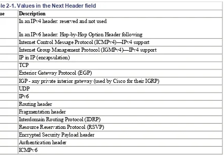
In IPv4, this field is the Protocol Type field. It was renamed in IPv6 to reflect the new organization of IP packets. If the next header is UDP or TCP, this field will contain the same protocol numbers as in IPv4— for example, protocol number 6 for TCP or 17 for UDP. But if Extension headers are used with IPv6, this field contains the type of the next Extension header. That header is located between the IP header and the TCP or UDP header. Table 2-1lists possible values in the Next Header field.
Table 2-1. Values in the Next Header field
Value Description
0
In an IPv4 header: reserved and not used
In an IPv6 header: Hop-by-Hop Option Header following 1 Internet Control Message Protocol (ICMPv4)—IPv4 support 2 Internet Group Management Protocol (IGMPv4)—IPv4 support 4 IP in IP (encapsulation)
6 TCP
8 Exterior Gateway Protocol (EGP)
59 No Next Header for IPv6 60 Destination Options header 88 EIGRP
89 OSPF
108 IP Payload Compression Protocol 115 Layer 2 Tunneling Protocol (L2TP)
132 Stream Control Transmission Protocol (SCTP) 134-254 Unassigned
255 Reserved
Header type numbers derive from the same range of numbers as protocol type numbers and should therefore not conflict with them.
The complete list of protocol numbers can be found in the appendix. For the most current list, go to IANA's web site at http://www.iana.org/assignments/protocol-numbers.
2.2.6 Hop Limit (1 Byte)
This field is analogous to the TTL field in IPv4. The TTL field contains a number of seconds, indicating how long a packet can remain in the network before being destroyed. Most routers simply decremented this value by one at each hop. This field was renamed to Hop Limit in IPv6. The value in this field now expresses a number of hops and not a number of seconds. Every forwarding node decrements the number by one.
2.2.7 Source Address (16 Bytes)
This field contains the IP address of the originator of the packet.
2.2.8 Destination Address (16 Bytes)
This field contains the IP address of the intended recipient of the packet. With IPv4, this field always contains the address of the ultimate destination of the packet. With IPv6, this field might not contain the IP address of the ultimate destination if a Routing header is present.
Figure 2-2. The IPv6 header in a trace file
This trace file shows all of the header fields I have discussed and how they are presented in a trace file. The Version field is set to 6 for IPv6. The Priority and the Flow Label fields are not used in this packet and are set to zero. The Payload Length is 40 and the Next Header value is set to 58 for ICMPv6. The Hop Limit is set to 128 and the Source and Destination addresses contain the link local addresses of my IPv6 nodes.
2.3 Extension Headers
The IPv4 header can be extended from a minimum of 20 bytes to 60 bytes in order to specify options such as Security Options, Source Routing, or Timestamping. This capacity has rarely been used because it causes a performance hit. For example, IPv4 hardware forwarding implementations have to pass the packet containing options to the main processor (software handling).
The simpler a packet header, the faster the processing. IPv6 has a new way to deal with options that has substantially improved processing. It handles options in additional headers called Extension headers.
The current IPv6 specification (RFC 2460) defines six Extension headers:
• Hop-by-Hop Options header
• Routing header
• Fragment header
• Destination Options header
• Authentication header
• Encrypted Security Payload header
The first four Extension headers are described in RFC 2460. The Authentication header is described in RFC 2402 and the Encrypted Security Payload header in RFC 2406.
Figure 2-3shows how Extension headers are used.
Figure 2-3. The use of Extension headers
Each Extension header is a multiple of 8 octets long. That way, subsequent headers can always be aligned. If a node is required to process the Next Header but cannot identify the value in the Next Header field, it is required to discard the packet and send an ICMPv6 Parameter Problem message back to the source of the packet. For details on ICMPv6 messages, refer to Chapter 4.
If more than one Extension header is used in a single packet, the following header order should be used (RFC 2460):
1. IPv6 header
2. Hop-by-Hop Options header
3. Destination Options header (for options to be processed by the first destination that appears in the IPv6 Destination address field, plus subsequent destinations listed in the Routing header)
4. Routing header 5. Fragment header 6. Authentication header
7. Encapsulating Security Payload header
8. Destination Options header (for options to be processed only by the final destination of the packet) 9. Upper-Layer header
In cases when IPv6 is encapsulated in IPv4, the Upper-Layer header can be another IPv6 header and can contain Extension headers that have to follow the same rules.
2.3.1 Hop-by-Hop Options Header
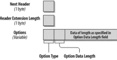
The format of the Hop-by-Hop Options header is shown in Figure 2-4.
Figure 2-4. Format of the Hop-by-Hop Options header
The following list describes each field:
Next Header (1 byte)
The Next Header field identifies the type of header that follows the Hop-by-Hop Options header. The Next Header field uses the values listed in Table 2-1, earlier in this chapter.
Header Extension Length (1 byte)
This field identifies the length of the Hop-by-Hop Options header in 8-byte units. The length calculation does not include the first 8 bytes.
Options (variable size)
There can be one or more options. The length of the options is variable and determined in the Header Extension Length field.
The Option Type Field, the first byte of the Options fields, contains information about how this option must be treated in case the processing node does not recognize the option. The value of the first two bits specifies the actions to be taken:
• Value 00: skip and continue processing.
• Value 01: discard the packet.
• Value 10: discard the packet and send ICMP Parameter Problem, Code 2 message to the packet's source address, pointing to the unrecognized option type.
• Value 11: discard the packet and send ICMP Parameter Problem, Code 2 message to the packet's source address only if the destination is not a multicast address.
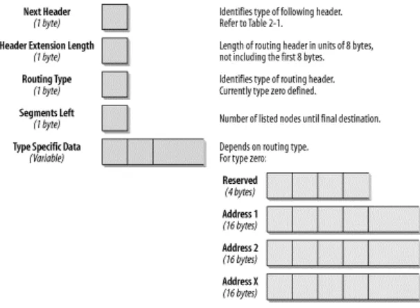
Figure 2-5. Format of the Routing header
The following list describes each field:
Next Header (1 byte)
The Next Header field identifies the type of header that follows the Routing header. It uses the same values as the IPv4 Protocol Type field (see Table 2-1, earlier in this chapter).
Header Extension Length (1 byte)
This field identifies the length of the Routing header in 8-byte units. The length calculation does not include the first 8 bytes.
Routing Type (1 byte)
This field identifies the type of Routing header. RFC 2460 describes Routing Type zero.
Segments Left (1 byte)
This field identifies how many nodes are left to be visited before the packet reaches its final destination.
Type-Specific Data (Variable-length)
The length of this field depends on the Routing Type. The length will always make sure that this complete header is a multiple of 8 bytes.
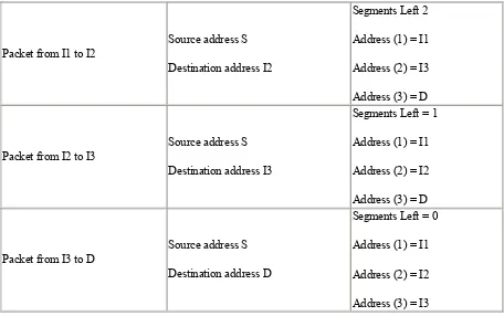
The only Routing Type described in RFC 2460 is a Type Zero Routing header. The first node that processes the Routing header is the node addressed by the Destination address field in the IPv6 header. This node decrements the Segments Left field by one and inserts the next address field from within the Routing header in the IPv6 header Destination address field. Then the packet is forwarded to the next hop that will again process the Routing header as described until the final destination is reached. The final destination is the last address in the Routing Header Data field. For example, Mobile IPv6 uses the Routing header. Any node sending a packet to a mobile node will send the packet to the mobile node's care-of-address. It will include a Routing header with one entry, the mobile node's home care-of-address. The mobile node swaps the Destination address in the IPv6 header with the entry in the Routing header and will reply with its home address as a source address as if it received the packet attached to its home network. For further discussion and definition of terms regarding Mobile IPv6, refer to Chapter 7.Figure 2-6shows the routing header in a trace file.
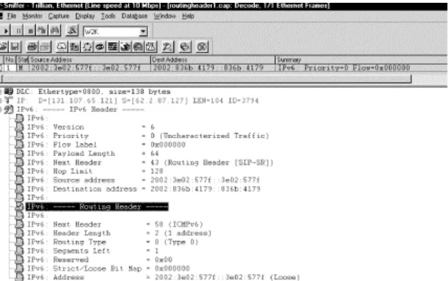
Figure 2-6. Routing header in a trace file
The Next Header field within the IPv6 header shows the value 43 for the Routing header. The Source and Destination addresses have the prefix 2002:, which is allocated to 6to4 sites. The Routing header contains the fields discussed earlier in this section. Next Header will be ICMPv6, value 58. The Header Length is two 8-byte units, which calculates to a total length of 16 bytes. The Segments Left field contains the value 1 because there is one address entry in the Options Fields. Finally, the Options field lists the addresses to be visited. In this case, there is only one entry. If a number of hosts is listed here, every forwarding node (that is, the destination IP address in the IPv6 header) takes the next entry from this host list, uses it as a new destination IP address in the IPv6 header, decrements the Segments Left field by one, and forwards the packet. This is done until the last host in the list is reached. RFC 2460 shows an example.
Packet from I1 to I2
Source address S
Destination address I2
Segments Left 2
Address (1) = I1
Address (2) = I3
Address (3) = D
Packet from I2 to I3
Source address S
Destination address I3
Segments Left = 1
Address (1) = I1
Address (2) = I2
Address (3) = D
Packet from I3 to D
Source address S
Destination address D
Segments Left = 0
Address (1) = I1
Address (2) = I2
Address (3) = I3
2.3.3 Fragment Header
An IPv6 host that wants to send a packet to an IPv6 destination uses Path MTU discovery to determine the maximum packet size that can be used on the path to that destination. If the packet to be sent is larger than the supported MTU, the source host fragments the packet. Unlike IPv4, with IPv6, a packet does not get fragmented by a router along the path. Fragmentation only occurs on the source host sending the packet. The destination host handles reassembly. A Fragment header is identified by a Next Header value of 44 in the preceding header. The format of the Fragment header is shown in Figure 2-7.
Figure 2-7. Format of the Fragment header
The following list describes each field:
Next Header (1 byte)
The Next Header field identifies the type of header that follows the Fragment header. It uses the same values as the IPv4 Protocol Type field. (See Table 2-1).
Not used; set to zero.
Fragment Offset (13 bits)
The offset in 8-byte units of the data in this packet relative to the start of the data in the original packet.
Reserved (2 bits)
Not used; set to zero.
M-Flag (1 bit)
Value 1 indicates more fragments; value zero indicates last fragment.
Identification (4 Bytes)
Generated by the source host in order to identify all packets belonging to the original packet. This field is usually implemented as a counter, increasing by one for every packet that needs to be fragmented by the source host.
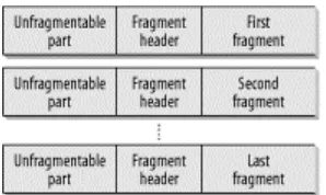
The initial unfragmented packet is referred to as the original packet. It has an unfragmentable part that consists of the IPv6 header, plus any Extension headers that must be processed by nodes along the path to the destination (i.e., Hop-by-Hop Options). The fragmentable part of the original packet consists of any Extension headers that need only to be processed by the final destination, plus the Upper-Layer headers and any data. Figure 2-8(RFC 2460) illustrates the fragmenting process.
Figure 2-8. Fragmentation with IPv6
The unfragmentable part of the original packet appears in every fragment, followed by the Fragmentation header, and then the fragmentable data. The IPv6 header of the original packet has to be slightly modified. The length field reflects the length of the fragment (excluding the IPv6 header) and not the length of the original packet.
Figure 2-9. Fragment header in a trace file
I created this Fragment header by generating an oversized ping from Marvin to Ford (Win2000 to Linux). The whole fragment set consists of two packets, the first of which is shown in Figure 2-9. In the IPv6 header, the Payload Length field has a value of
1456
, which is the length of the fragmentation header and this one fragment, not the length of the whole original packet. The Next Header field specifies the value44
, which is the value for the Fragment header. This field is followed by the Hop Limit field and by the Source and Destination IP addresses. The first field in the Fragment header is the Next Header field. Because this is a ping, it contains the value58
for ICMPv6. And because this is the first packet in the fragment set, the value in the Offset field is zero and the M-Flag is set to one, which means there are more fragments to come. The Identification field is set to one and has to be identical in all packets belonging to this fragment set. Figure 2-10shows the second packet of the fragment set.Figure 2-10. The last packet in the fragment set
2.3.4 Destination Options Header
A Destination Options header carries optional information that is examined by the destination node only. The Next Header value identifiying this type of header is the value
60
.Figure 2-11shows the format of the Destination Options header.Figure 2-11. Format of the Destination Options header
The following list describes each field:
Next Header (1 byte)
The Next Header field identifies the type of header that follows the Destination Options header. It uses the same values listed in Table 2-1, earlier in this chapter.
Header Extension Length (1 byte)
This field identifies the length of the Destination Options header in 8-byte units. The length calculation does not include the first 8 bytes.
Options (variable size)
There can be one or more options. The length of the options is variable and determined in the Header Extension Length field.
Chapter 3. IPv6 Addressing
An IPv4 address has 32 bits and is familiar. An IPv6 address has 128 bits and looks wild. Extending the address space was one of the driving reasons to develop IPv6, along with optimization of routing tables, especially on the Internet. This chapter will help you become familiar with the extended address space and will also explain how IPv6 addressing works and why it has been designed the way it is. The IPv6 addressing architecture is defined in RFC 2373, which obsoletes RFC 1884.
3.1 Address Types
IPv4 knows unicast, broadcast, and multicast addresses. With IPv6, the broadcast address is not used anymore; multicast addresses are used instead. This is good news because broadcasts are a problem in most networks. The anycast address, a new type of address introduced with RFC 1546, is now used with IPv6.
3.1.1 Unicast, Multicast, and Anycast Addresses
An IPv6 address can be classified into one of three categories:
Unicast
A unicast address uniquely identifies an interface of an IPv6 node. A packet sent to a unicast address is delivered to the interface identified by that address.
Multicast
A multicast address identifies a group of IPv6 interfaces. A packet sent to a multicast address is processed by all members of the multicast group.
Anycast
An anycast address is assigned to multiple interfaces (usually on multiple nodes). A packet sent to an anycast address is delivered to only one of these interfaces, usually the nearest one.
3.1.2 Some General Rules
IPv6 addresses are assigned to interfaces, as in IPv4, not to nodes, as in OSI, so each interface of a node needs at least one unicast address. A single interface can also be assigned multiple IPv6 addresses of any type (unicast, multicast, anycast). A node can therefore be identified by the address of any of its interfaces. It is also possible to assign one unicast address to multiple interfaces for load-sharing reasons, but if you do this, you need to make sure that the hardware and the drivers support it. With IPv6, all zeros and ones are legal values for any field in an address.
Figure 3-1. IPv6 general address format
The global routing prefix is used to identify a special address, such as multicast, or an address range assigned to a site. A subnet ID is used to identify a link within a site. (The subnet ID may also be referred to as subnet prefix or simply "subnet.") A subnet ID is associated with one link. Multiple subnet IDs may be assigned to one link. An interface ID is used to identify an interface on a link and needs to be unique on that link
3.2 Address Notation
An IPv6 address has 128 bits, or 16 bytes. The address is divided into eight, 16-bit hexidecimal blocks, separated by colons. For example:
FE80:0000:0000:0000:0202:B3FF:FE1E:8329
To make life easier, some abbreviations are possible. For instance, leading zeros in a 16-bit block can be skipped. The example address now looks like:
FE80:0:0:0:202:B3FF:FE1E:8329
A double colon can replace consecutive zeros, or leading or trailing zeros, within the address. If we apply this rule, our address looks as follows:
FE80::202:B3FF:FE1E:8329
Note that the double colon can appear only once in an address. The reason for this rule is that the computer always uses a full 128-bit binary representation of the address, even if the displayed address is simplified. When the computer finds a double colon, it expands it with as many zeros as are needed to get 128 bits. If an address had two double colons, the computer would not know how many zeros to add for each. So the IPv6 address
CAFF:CA01:0000:0056:0000:ABCD:EF12:1234
can be represented in the following ways (note the two possible positions for the double colon):•
CAFF:CA01:0000:0056:0000:ABCD:EF12:1234
•
CAFF:CA01::56:0:ABCD:EF12:1234
3.3 Prefix Notation
The notation for prefixes has also been specified in RFC 2373. A format prefix is the high-order bits of an IP address used to identify the subnet or a specific type of address (refer to Table 3-2). In newer drafts, it is called the global routing prefix. The prefix notation is very similar to the way IPv4 addresses are written in Classless Interdomain Routing (CIDR) notation, and it is also commonly used for subnetted IPv4 addresses. The notation appends the prefix length, written as a number of bits with a slash, which leads to the following format:
IPv6 address/prefix length
The prefix length specifies how many left-most bits of the address specify the prefix. This is another way of noting a subnet mask. Remember, a subnet mask specifies the bits of the IPv4 address that belong to the network ID. The prefix is used to identify the subnet that an interface belongs to and is used by routers for forwarding. The following example explains how the prefix is interpreted. Consider the IPv6 prefix notation
2E78:DA53:12::/40
. To understand this address, let's convert the hex into binary as shown in Table 3-1.Table 3-1. Understanding prefix notation
Hex notation Binary notation Number of bits 2E 78
DA 53
12
00101110 01111000
11011010 01010011
00010010
16 bits
16 bits
8 bits, total 40 bits
The compressed notation (replacing a sequence of zeros with a double colon) is also applicable to the prefix representation. It should be used carefully, though, because there are often two or more ranges of zeros within an address, and only one can be compressed.
To play with the example in the previous section, look at the prefix notation. The address is
CAFF:CA01:0000:0056:0000:ABCD:EF12:1234/64
, but now we're just interested in the prefix of the address. Can we compress it as follows?CAFF:CA01::56/64
In order to verify this notation, we'll expand the address again. If we follow the notation rules, we end up with an address of
CAFF:CA01:0000:0000:0000:0000:0000:0056
, withCAFF:CA01:0000:0000
for the 64-bit prefix. This is not the same as the original address and prefix. To make sure the address interpretation is unambiguous, we have to note it asCAFF:CA01:0:56::/64
3.4 Format Prefixes
Table 3-2. List of assigned prefixes
Allocation Prefix
binary
Prefix hex
Fraction of address space
Reserved 0000 0000 ::0/128 1/256
Reserved for NSAP allocation
Reserved for IPX allocation (deprecated in later draft)
0000 001
0000 010
1/128
1/128
Aggregatable global unicast addresses 001 1/8 Link-local unicast addresses
Site-local unicast addresses
1111 1110 10
1111 1110 11
FE80::/10
FEC0::/10
1/1024
1/1024 Multicast addresses 1111 1111 FF00::/8 1/256
Some special addresses are assigned out of the reserved address space with the binary prefix 0000 0000. These include the unspecified address, the loopback address, and IPv6 addresses with embedded IPv4 addresses, which will be discussed in detail later in this chapter. In drafts released after RFC 2373, the prefix for IPX has been removed. (The most recent draft, at the time of writing, is available at
http://www.ietf.org/internet-drafts/draft-ietf-ipngwg-addr-arch-v3-08.txt.)
Unicast addresses can be distinguished from multicast addresses by their prefix. Globally unique unicast addresses have a high-order byte starting with 001. An IPv6 address with a high-order byte of 1111 1111 (FF in hex) is always a multicast address. For more information about multicast addresses, refer to Section 3.8, later in this chapter.
Anycast addresses are taken from the unicast address space, so they can't be identified as anycast just by looking at the prefix. If you assign a unicast address to multiple interfaces, thereby making it an anycast address, you have to configure the interfaces so that they all know this address is an anycast address. For more information about anycast addresses, refer to Section 3.7, later in this chapter.
Addresses in the prefix range 001 to 111 should use a 64-bit interface identifier that follows the EUI-64 (Extended Unique Identifier) format (except for multicast addresses with the prefix 1111 1111). The EUI-64 is a unique identifier defined by the Institute of Electrical and Electronics Engineers (IEEE); for more information, refer to http://standards.ieee.org/regauth/oui/tutorials/EUI64.html. Appendix A of RFC 2373 explains how to create EUI-64 identifiers, and more details can be found in the link-specific RFCs, such as "IPv6 over Ethernet" or "IPv6 over FDDI." Chapter 7and this book's Appendix contain a short discussion and a complete list of these RFCs, respectively.
A host uses an identifier following the EUI-64 format during autoconfiguration. For example, when our Windows 2000 host Marvin autoconfigures for a link-local address on an Ethernet interface, the 64-bit interface identifier has to be created from the 48-bit (6-Byte) Ethernet MAC address. First, the hex digits
To learn how IPv6 autoconfiguration works and what a stateless address is, refer to Chapter 4.
3.5 Address Privacy
The privacy of autoconfigured IPv6 addresses using the interface identifier is a major issue in the IETF. If an IPv6 address is built using the MAC identifier, your Internet access could be traced because this identifier is unique to your interface. Part of the concern is the result of a misunderstanding. An IPv6 node can have an address based on the interface identifier, but this is not a requirement. As an alternative, the IPv6 device can have an address like the ones currently used with IPv4, static and manually configured or dynamically assigned by a DHCP server. In early 2001, RFC 3041, "Privacy Extensions for Stateless Address Autoconfiguration in IPv6," was published; it introduces a new kind of address, available only in IPv6, that contains a random number in place of the factory-assigned serial number. This address can also change over time. An Internet device that is a target for IP communication—for instance, a web or FTP server—needs a unique and stable IP address. But a host running a browser or an FTP client does not need to have the same address every time it connects to the Internet. With the address architecture in IPv6, you can choose between two types of addresses:
Unique stable IP addresses
Assigned through manual configuration, a DHCP server, or autoconfiguration using the interface identifier
Temporary transient IP addresses
Assigned using a random number in place of the interface identifier
3.5.1 Link- and Site-Local Addresses
With IPv4, organizations often use IP addresses from the private range, as defined in RFC 1918. The addresses reserved for private use should never be forwarded over Internet routers, but should instead be confined to the organization's network. For connection to the Internet, Network Address Translation (NAT) maps internal private addresses to publicly registered IPv4 addresses.
Figure 3-2. Link- and site-local address format
In hexadecimal notation, a link-local address is identified by the prefix
fe80
; a site-local address is identified by the prefixfec0
.3.6 Aggregatable Global Unicast Address
Aggregatable global unicast addresses are identified by the prefix
001
, as shown earlier, in Table 3-2. The initial address specification defined provider-based addresses; the name has been changed to aggregatable global unicast address. The name change reflects the addition of an ISP-independent means of aggregation called exchange-based aggregation.The prefix is followed by five components, as shown in Figure 3-3.
Figure 3-3. Format of the aggregatable global unicast address
Many discussions have been going on in recent months, and the area of address assignment is still evolving. A number of clarifications are described in the Internet draft available at
http://www.ietf.org/internet-drafts/draft-ietf-ipngwg-addr-arch-v3-08.txt. (Note that the draft number may have increased by one or more when you go there.)
3.6.1 International Registry Services and Current Address Allocations
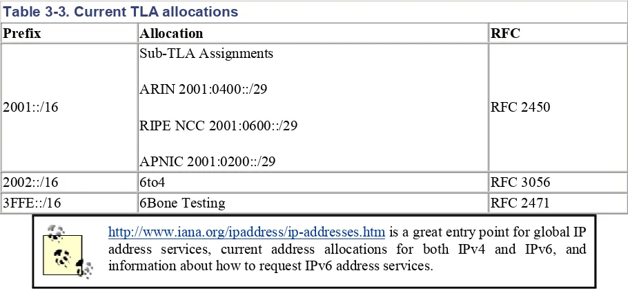
Several TLA allocations have been made, as listed in Table 3-3.
Table 3-3. Current TLA allocations
Prefix Allocation RFC
2001::/16
Sub-TLA Assignments
ARIN 2001:0400::/29
RIPE NCC 2001:0600::/29
APNIC 2001:0200::/29
RFC 2450
2002::/16 6to4 RFC 3056
3FFE::/16 6Bone Testing RFC 2471
http://www.iana.org/ipaddress/ip-addresses.htmis a great entry point for global IP address services, current address allocations for both IPv4 and IPv6, and information about how to request IPv6 address services.
ISPs can use the following sites to access their regional registry for information about IPv6 address registration. For end users, IPv6 address allocation is managed by their ISP.
• ARIN Registration Services, http://www.arin.net/library/guidelines/ipv6_initial.html
• RIPE-NCC Registration Services, http://www.ripe.net/ripencc/mem-services/registration/ipv6.html
• APNIC Registration FAQ, http://www.apnic.net/faq/IPv6-FAQ.html
As I've already mentioned, address allocation is a work in progress. Information about the latest status, clarifications, and current practices can be found at http://www.arin.net. There is also an informational RFC called "IAB/IESG Recommendations on IPv6 Address Allocations to Sites," numbered RFC 3177.
3.6.2 Special Addresses
There are a number of special addresses that we need to discuss. The first part of the IPv6 address space with the prefix of
0000 0000
is reserved. Out of this prefix, special addresses have been defined as follows:The unspecified address
The loopback address
The IPv4 loopback address,
127.0.0.1
, is probably familiar. It is helpful in troubleshooting and testing the IP stack because it can be used to send a packet to the protocol stack, without sending it out on the subnet. With IPv6, the loopback address works the same way and is represented as0:0:0:0:0:0:0:1
, abbreviated::1
. It should never be statically or dynamically assigned to an interface.The next three sections describe three different types of addresses that have been specified to be used with different transition mechanisms. These virtual interfaces are called pseudo-interfaces.
3.6.2.1 IPv6 addresses with embedded IPv4 addresses
Because the transition to IPv6 will be gradual, two special types of addresses have been defined for backward compatibility with IPv4. Both are described in RFC 2373:
IPv4-compatible IPv6 address
This type of address is used to tunnel IPv6 packets dynamically over an IPv4 routing infrastructure. IPv6 nodes that use this technique are assigned a special IPv6 unicast address that carries an IPv4 address in the low-order 32 bits.
IPv4-mapped IPv6 address
This type of address is used to represent the addresses of IPv4-only nodes. This address can be used by an IPv6 node to send a packet to an IPv4-only node. The address also carries the IPv4 address in the low-order 32 bits of the address.
Figure 3-4shows the format of both these addresses.
Figure 3-4. Format of IPv6 addresses with an embedded IPv4 address
Figure 3-5. Format of the 6to4 address
The prefix has a total length of 48 bits. The IPv4 address in the prefix must be a public IPv4 address and is represented in hexadecimal notation. For instance, if you configure an interface for 6to4 with an IPv4 address of
62.2.84.115
, the 6to4 address is2002:3e02:5473::/48
. Through this interface, all IPv6 hosts on this link can tunnel their packets over the IPv4 infrastructure.3.6.2.3 ISATAP addresses
A new automatic tunneling mechanism, called Intra-Site Automatic Tunnel Addressing Protocol (ISATAP), is currently being defined. It is designed to let IPv6 hosts communicate easily within an IPv4 infrastructure. It is still in the draft stage, but it might become popular. Windows XP already includes an implementation of ISATAP (described in Chapter 11). It uses a type identifier of
0xFE
for specifying an IPv6 address with an embedded IPv4 address. The format of an ISATAP address according to the current draft is shown in Figure 3-6.Figure 3-6. Format of the ISATAP address
The first 64 bits follow the format of the aggregatable global unicast address. IANA owns the IEEE Organizationally Unique Identifier (OUI)
00 00 5E
and specifies the EUI-48 format interface identifier assignments within that OUI. The next 8 bits are used for a type identifier to indicate that this is an IPv6 address with an embedded IPv4 address. The type identifier is0xFE
. The last 32 bits contain the embedded IPv4 address, which can be written in dotted decimal notation or in hexadecimal representation.Assume we have a host with an IPv4 address of
192.168.0.1
and the host is assigned a 64-bit prefix of3FFE:1a05:510:200::/64
. The ISATAP address for this host is3FFE:1a05:510:200:0:5EFE:192.168.0.1
. Alternatively, you can use the hexadecimal representation for the IPv4 address, in which case the address is written3FFE:1a05:510:200:0:5EFE:C0A8:1.
The link-local address for this host is
FE80::5EFE:192.168.0.1
and the site-local address isFEC0::200:0:5EFE:192.168.0.1
.3.7 Anycast Address
As already mentioned, anycast addresses are in the same address range as aggregatable global unicast addresses, and each participating interface must be configured as having an anycast address. Within the region where the interfaces containing the same anycast addresses are, each host must be advertised as a separate entry in the routing tables. If the anycast interfaces have no definable region, each anycast entry (in the worst case) has to be propagated throughout the Internet, which obviously does not scale. It is expected, therefore, that support for such global anycast addresses will be either unavailable or very restricted. Until there is more experience gained, the following restrictions are defined in RFC 2373.
• An anycast address must not be used as the source address of an IPv6 packet.
• An anycast address must not be assigned to an IPv6 host. It may be assigned only to an IPv6 router.
An expected use of anycast addresses is to identify a set of routers providing access to a particular routing domain. One example is the 6to4 relay anycast address that is specified in RFC 3068 and described in
Chapter 10. Another possibility is to configure with a specific anycast address all the routers within a corporate network that provide access to the Internet. Whenever a packet is sent to that anycast address, it will be delivered to the closest router that provides Internet access.
A required anycast address is the subnet-router anycast address , which is defined in RFC 2373 and shown in Figure 3-7.
Figure 3-7. Format of the subnet-router anycast address
Basically, the address is like a regular unicast address with a prefix specifying the subnet and an identifier that is set to all zeros. A packet sent to this address will be delivered to one router on that subnet. All routers are required to support the subnet-router anycast address for subnets to which they have interfaces.
RFC 2526 provides more information about anycast address formats and specifies other reserved subnet anycast addresses and IDs. A reserved subnet anycast address can have one of two formats, as shown in
Figure 3-8.
Table 3-4. Reserved anycast IDs
Decimal Hexadecimal Description
127 7F Reserved
126 7E Mobile IPv6 Home-Agents anycast
0-125 00-7D Reserved
3.8 Multicast Address
A multicast address is an identifier for a group of nodes, identified by the high-order byte
FF
, or1111
1111
in binary notation (refer to Table 3-2). A node can belong to more than one multicast group. Multicast exists in IPv4, but it has been redefined and improved for IPv6. The multicast address format is shown in Figure 3-9.Figure 3-9. Format of the multicast address
The first byte identifies the address as a multicast address. The next 4 bits are used for Flags, defined as follows: The first 3 bits of the Flag field must be zero; they are reserved for future use. The last bit of the Flag field indicates whether this address is permanently assigned—i.e., one of the well-known multicast addresses assigned by the IANA—or a temporary multicast address. A value of zero for the last bit defines a well-known address; a value of one indicates a temporary address. The Scope field is used to limit the scope of a multicast address. The possible values are shown in Table 3-5.
Table 3-5. Values for the Scope field
Value Description
0 Reserved
1 Node-local scope (name changed to interface-local in new draft) 2 Link-local scope
3, 4 Unassigned 5 Site-local scope 6, 7 Unassigned
8 Organization-local scope 9, A, B, C, D Unassigned
E Global scope
F Reserved
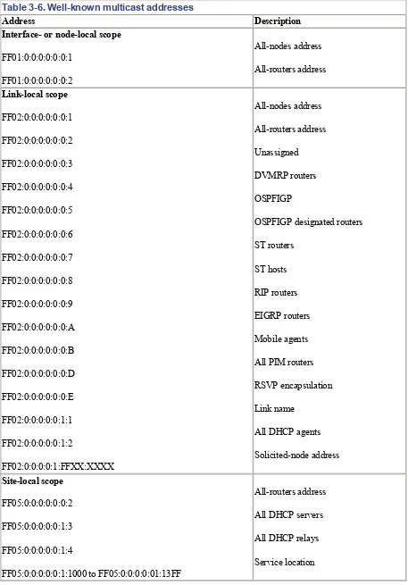
3.8.1 Well-Known Multicast Addresses
Table 3-6. Well-known multicast addresses
Address Description Interface- or node-local scope
FF01:0:0:0:0:0:0:1
FF01:0:0:0:0:0:0:2
All-nodes address
All-routers address
Link-local scope
FF02:0:0:0:0:0:0:1
FF02:0:0:0:0:0:0:2
FF02:0:0:0:0:0:0:3
FF02:0:0:0:0:0:0:4
FF02:0:0:0:0:0:0:5
FF02:0:0:0:0:0:0:6
FF02:0:0:0:0:0:0:7
FF02:0:0:0:0:0:0:8
FF02:0:0:0:0:0:0:9
FF02:0:0:0:0:0:0:A
FF02:0:0:0:0:0:0:B
FF02:0:0:0:0:0:0:D
FF02:0:0:0:0:0:0:E
FF02:0:0:0:0:0:1:1
FF02:0:0:0:0:0:1:2
FF02:0:0:0:0:1:FFXX:XXXX
All-nodes address
All-routers address
Unassigned
DVMRP routers
OSPFIGP
OSPFIGP designated routers
ST routers
ST hosts
RIP routers
EIGRP routers
Mobile agents
All PIM routers
RSVP encapsulation
Link name
All DHCP agents
Solicited-node address
independent of scopes is long and is available in the Appendix or in RFC 2375. All those addresses are noted beginning with
FF0X
;X
is the placeholder for a variable scope value.As an example, let's look at the one described in RFC 2373. There is a multicast group ID defined for all NTP servers. The multicast group ID is
0x101
. This group ID can be used with different scope values as follows:FF01:0:0:0:0:0:0:101
All NTP servers on the same node as the sender
FF02:0:0:0:0:0:0:101
All NTP servers on the same link as the sender
FF05:0:0:0:0:0:0:101
All NTP servers on the same site as the sender
FF0E:0:0:0:0:0:0:101
All NTP servers in the Internet
Temporarily assigned multicast addresses are meaningful only within a defined scope.
Multicast addresses should not be used as a source address in IPv6 packets or appear in any routing header.
To learn how multicast addresses are managed, refer to Section 4.9in Chapter 4.
3.8.2 Solicited-Node Multicast Address
The solicited-node multicast address is a multicast address that every node must join for every unicast and anycast address it is assigned. It is used in the Duplicate Address Detection (DAD) process, described in
Chapter 4. RFC 2373 specifies the solicited-node multicast address.
This address is formed by taking the low-order 24 bits of an IPv6 address (the last part of the host ID) and appending those bits to the well-known prefix
FF02:0:0:0:0:1:FF00::/104
. Thus, the range for solicited-node multicast addresses goes fromFF02:0:0:0:0:1:FF00:0000
toFF02:0:0:0:0:1:FFFF:FFFF
.For example, our host Marvin has the MAC address
00-02-B3-1E-83-29
and the IPv6 addressfe80::202:b3ff:fe1e:8329
. The corresponding solicited-node multicast address is3.9 Required Addresses
The standard specifies that each host must assign the following addresses to identify itself:
• Its link-local address for each interface
• Any assigned unicast addresses
• The loopback address
• The all-nodes multicast address
• Solicited-node multicast address for each of its assigned unicast and anycast addresses
• Multicast addresses of all other groups to which the host belongs
A router needs to recognize all of the above plus the following:
• The subnet-router anycast address for the interfaces for which it is configured to act as a router on each link
• All anycast addresses with which the router has been configured
• The all-routers multicast address
• Multicast addresses of all other groups to which the router belongs
Chapter 4. ICMPv6
If you are familiar with IPv4, the Internet Control Message Protocol (ICMP) for IPv4 is probably a good friend of yours: it gives important information about the health of the network. ICMPv6 is the version that works with IPv6. It reports errors if packets cannot be processed properly and sends informational messages about the status of the network. For example, if a router cannot forward a packet because it is too large to be sent out on another network, it sends back an ICMP message to the originating host. The source host can use this ICMP message to determine a better packet size and then resend the data. ICMP also performs diagnostic functions, such as the well-known ping, which uses ICMP Echo Request and Echo Reply messages to test availability of a node.
ICMPv6 is much more powerful than ICMPv4 and contains new functionality, as described in this chapter. For instance, the Internet Group Management Protocol (IGMP) function that manages multicast group memberships with IPv4 has been incorporated into ICMPv6. The same is true for the Address Resolution Protocol/Reverse Address Resolution Protocol (ARP/RARP) function that is used in IPv4 to map layer 2 addresses to IP addresses (and vice versa). Neighbor discovery (ND) is introduced; it uses ICMPv6 messages in order to determine link-layer addresses for neighbors attached to the same link, to find routers, to keep track of which neighbors are reachable, and to detect changed link-layer addresses. ICMPv6 also supports Mobile IPv6, which is described in Chapter 7. ICMPv6 is part of IPv6 and it must be implemented fully by every IPv6 node. It is defined in RFC 2463 (obsoletes RFC 1885). Neighbor discovery is defined in RFC 2461 (obsoletes RFC 1970).
4.1 General Message Format
There are two classes of ICMP messages:
ICMP error messages
Error messages have a zero in the high-order bit of their message Type field. ICMP error message types are therefore in the range 0 to 127.
ICMP informational messages
Informational messages have a one in the high-order bit of their message Type field. ICMP informational message types are therefore in the range 128 to 255.
An IPv6 header and zero or more extension headers precede every ICMPv6 message. The header just preceding the ICMP header has a next header value of 58. This value is different from the value for ICMPv4 (which has the value 1).
The values for the next header field are discussed in Chapter 2.
The following message types are described in RFC 2463:
• ICMPv6 error messages
o Destination Unreachable (message type 1)
o Packet Too Big (message type 2)
o Time Exceeded (message type 3)
o Parameter Problem (message type 4)
• ICMPv6 informational messages
o Echo Reply (message type 129)
For the most current list of ICMPv6 message types, refer to the Internet Assigned Number Authority (IANA) at http://www.iana.org/assignments/icmpv6-parameters. All IPv4 ICMP parameters can be found at
http://www.iana.org/assignments/icmp-parameters.
All ICMPv6 messages have the same general header structure, shown in Figure 4-1. Notice that the first three fields for type, code, and checksum have not changed from ICMPv4.
Figure 4-1. General ICMPv6 header format
4.1.1 Type (1 Byte)
This field specifies the type of message, which determines the format of the remainder of the message.
Table 4-1and Table 4-2list ICMPv6 message types and message numbers.
4.1.2 Code (1 Byte)
The Code field depends on the message type and allows for more granular information in certain cases. Refer to Table 4-1and Table 4-2for a detailed list.
4.1.3 Checksum (2 Bytes)
The Checksum field is used to detect data corruption in the ICMPv6 header and in parts of the IPv6 header. In order to calculate the checksum, a node must determine the source and destination address in the IPv6 header. If the node has more than one unicast address, there are rules for choosing the address (refer to RFC 2463 for details). There is also a pseudoheader included in the checksum calculation, which is new with ICMPv6.
Table 4-1. ICMPv6 error messages and code types
Message
number Message type Code field
1 Destination Unreachable
0 = no route to destination
1 = communication with destination administratively prohibited
2 = beyond scope of source address (draft)
3 = address unreachable
4 = port unreachable
2 Packet Too Big Code field set to 0 (zero) by the sender and ignored by the receiver
3 Time Exceeded
0 = hop limit exceeded in transit
1 = fragment reassembly time exceeded
4 Parameter Problem
0 = erroneous header field encountered
1 = unrecognized next header type encountered
2 = unrecognized IPv6 option encountered
The pointer field identifies the octet offset within the invoking packet where the error was detected. The pointer points beyond the end of the ICMPv6 packet if the field in error is beyond what can fit in the maximum size of an ICMPv6 error message.
Note that the message numbers and types have substantially changed compared to ICMPv4. ICMP for IPv6 is a different protocol, and the two versions of ICMP are not compatible. Your analyzer should properly decode all this information, so you do not have to worry memorizing it.
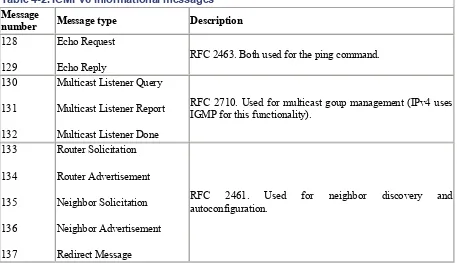
Table 4-2. ICMPv6 informational messages
Message
number Message type Description 128
129
Echo Request
Echo Reply
RFC 2463. Both used for the ping command.
130
131
132
Multicast Listener Query
Multicast Listener Report
Multicast Listener Done
RFC 2710. Used for multicast goup management (IPv4 uses IGMP for this functionality).
133 134 135 136 137 Router Solicitation Router Advertisement Neighbor Solicitation Neighbor Advertisement Redirect Message
138
139
140
Router Renumbering
ICMP Node Information Query
ICMP Node Information Response
RFC 2894
Draft number at the time of writing:
http://www.ietf.org/internet-drafts/draft-ietf-ipngwg-icmp-name-lookups-09.txt.
141
142
Inverse ND Solicitation
Inverse ND Adv Message
RFC 3122
RFC 3122
150
151
152
153
ICMP Home Agent Address Discovery Request Message