MIPA
LAPORAN
PERCEPATAN PROFESOR
DESAIN DAN PEMBUATAN ALAT UKUR GETARAN
FREKUENSI RENDAH BERBASIS SENSOR
MAGNETIK
Oleh:
Dr. Yulkifli, S.Pd, M.Si.
NIP. 19730702 200312 1 002
Dibiayai oleh Dana DIPA UNP
FAKULTAS MATEMATIKA DAN ILMU PENGETAHUAN ALAM UNIVERSITAS NEGERI PADANG
Halaman Pengesahan
1. Judul Penelitian Hibah : Desain dan Pembuatan Alat Ukur Getaran Frekuensi Rendah Berbasis Sensor Magnetik
2. Ketua Peneliti
a. Nama Lengkap : Dr. Yulkifli, S.Pd, M.Si b. Jenis Kelamin : Laki-laki
c. NIP : 19730702 200013 1 002
d. Jabatan Struktural : -e. Jabatan Fungsional : Lektor
f. Fakultas/Jurusan : FMIPA / Fisika
g. Pusat Penelitian : Universitas Negeri Padang
h. Alamat : Jl. Prof. DR. Hamka , Air Tawar Padang, 25131. i. Telepon/Faks : 0751-7053902 / 0751-7055628
j. Alamat Rumah : Komplek Perumahan Pratama II Blok D No 2 Lubuk Buaya Padang.
k. Telepon/Faks/E-mail : 081363413004-/ [email protected] 3. Jangka Waktu Penelitian : 1 Tahun
4. Pembiayaan
a. Jumlah biaya yang diajukan ke Dikti : Rp.
-b. Jumlah biaya : Rp.
15.000.000,-Padang, 28 November 2012
Mengetahui, Peneliti,
Dekan FMIPA,
Universitas Negeri Padang
(Prof. Dr. Lufri, M.S.) (Dr. Yulkifli, S.Pd,M.Si.)
NIP. 19610510 198703 1 020 NIP. 19730702 200013 1 002
Menyetujui, Ketua Lembaga Penelitian Universitas Negeri Padang
ABSTRAK
Keberadaan instrumen pengukur dan pengontrol dalam sebuah industri, pembangunan jembatan layang seperti Suramadu, bendungan dan pembangunan lainya adalah sangat penting agar dapat memberikan peringatan dini atau early warning kepada pemakainya. Salah satu instrumen tersebut adalah sensor. Sensor harus memiliki sensitivitas dan resolusi yang baik, mudah dioperasikan dan harganya murah dan mudah untuk diperoleh. Sensor yang ada di pasaran saat ini harganya sangat mahal, hal ini disebabkan karena proses fabrikasinya komplek dan memerlukan proses yang lama karena didatangkan dari luar negeri. Melalui penelitian ini akan dikembangkan sensor getaran yang dapat mendeteksi frekuensi rendah < 10 Hz berbasis sensor magnetik fluxgate. Sensor fluxgate
memiliki keunggulan antara lain dapat dibuat dengan proses sederhana memiliki ukuran kecil, kebutuhan daya rendah, rentang pengukuran cukup lebar, mempunyai sensitivitas dan reslolusi tinggi sehingga dapat diaplikasikan secara luas seperti alat ukur magnetik/elektromagnetik, pemetaan, karakterisasi batuan, navigasi (kompas), biomagnetik dan ruang angkasa.
Penelitian dilakukan secara bertahap, yang meliputi: tahap pertama: pemilihan sensor magnetik fluxgate yang cocok untuk menghasilkan frekuensi rendah, pembuatan rangkaian pengolah sinyal dan interfacing. Tahap kedua: pembuatan prototip sensor getaran, pengujian karakteristik sensor terhadap sumber pengetar, dan aplikasi pada getaran sebuah objek. Diharapkan dapat dihasilkan prototip sensor getaran yang kompatibel untuk menjadi alat ukur getaran khususnya getaran dengan frekuensi rendah yang dapat dikembangkan sebagai alat ukur getaran gempa.
I. PENDAHULUAN 1. Latar Belakang
Besarnya kompetisi di pasar bebas mengharuskan pengembangan instrumen yang terus menerus baik dari sisi kualitas, harga maupun keandalannya, salah satu instrumen tersebut adalah sensor. Saat ini teknologi sensor telah memasuki bidang aplikasi baru dan pasar yang semakin meluas seperti otomatif,Riset and development , rumah cerdas (smart home) dan teknologi pengolahan (Intechno, 2008). Sensor-sensor yang digunakan harus memiliki sensitivitas dan resolusi yang baik, mudah dioperasikan, harganya murah dan mudah untuk diperoleh, sedangkan sensor yang ada di pasaran saat ini harganya sangat mahal dan susah untuk diperoleh, hal ini disebabkan karena proses fabrikasinya komplek dan memerlukan proses yang lama karena harus didatangkan dari luar negeri. Untuk mengatasi kendala-kendala di atas peneliti sudah mengembangkan beberapa buah sensor antara lain sensor magnetik Fluxgate.
Berdasarkan hasil penelitian sebelumnya penulis telah berhasil membuat sensor
fluxgate dengan resolusi < 10 nT, kemampuannya dalam mendeteksi medan magnetik lemah ±20 uT (Yulkifli, dkk., 2008) dan pengukuran perubahan posisi objek (jarak orde kecil) dengan resolusi 260 µm (Yulkifli, dkk., 2007b). Perubahan posisi objek akan menyebabkan berubahnya medan magnet objek tersebut, perubahan inilah yang dijadikan sebagai prinsip dasar aplikasi sensor fluxgate menjadi sensor getaran, terutama getaran dengan amplitudo kecil. Berdasarkan potensi ini maka sangat terbuka peluang untuk mengaplikasikannya menjadi sensor getaran khsususnya getaran frekuensi rendah seperti getaran pada gempa bumi. Sensor getaran yang sering digunakan dalam industri adalah
piezoelectric, capacitance, null-balance, strain gage, resonance beam, piezoresistive dan
magnetic induction, saat pengukuran sensor-sensor tersebut harus menempel di objek yang akan diamati getarannya (kontak dengan objek), sedangkan kelebihan sensorfluxgate
tidak perlu kontak dengan objek yang diamatinya (NDT) sehingga saat pengukuran tidak perlu menganggu aktivitas objek yang sedang beroperasi.
2. Tujuan dan Manfaat Penelitian a. Tujuan penelitian
Adapun tujuan penelitian ini adalah :
1. Desain dan pembuatan sensor getaran frekuensi rendah berbasis sensor magnetik
2. Prototip sensor getaran untuk mengukur getaran sebuah objek bergetar.
b. Manfaat Penelitian
Penelitian desain dan pegembangan sensor-sensor berbasis magnetik ini sangat berguna bagi dunia industri, pembangunan dan pendidikan (R & D) di Indonesia. Perkembangan industri yang sangat cepat dan pembangunan sarana dan prasarana di masa modern seperti sarana transportasi baik darat maupun udara yang cenderung serba otomatis dan sensorisasi akan mendorong pemanfaatan dari hasil penelitian ini. Dengan luasnya aplikasi dari sensor magnetik, terbuka peluang untuk penerapan teknologi ke arah komersial untuk diproduksi secara massal di dalam negeri. Penggunaan produksi negeri sendiri dapat memajukan industri dan perekonomian di dalam negeri. Selain itu akan dapat menghemat devisa negara karena kebutuhan akan sensor selama ini di impor dari luar negeri. Disamping memiliki arti ekonomis yang sangat besar, hasil penelitian ini juga memiliki arti kebanggaan nasional karena riset ini sangat memberi peluang kepada Indonesia untuk ikut berbicara dalam tingkat dunia.
II. STUDI PUSTAKA A. Tinjauan Kebutuhan Sensor
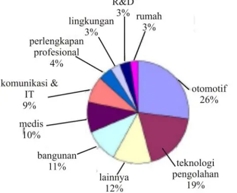
Meningkatnya kebutuhan untuk otomatisasi, keamanan dan kenyamanan menggiring orang untuk mengembangkan sensor dan sistem sensor baru dengan prinsip dan metoda yang berbeda-beda. Dari data mengenai pasar sensor dunia diketahui bahwa perkembangan rata-rata produksi sensor dalam sepuluh tahun terakhir meningkat 4.5% setiap tahunnya, dengan prediksi komposisi kebutuhan ditunjukkan pada Gambar 1.
Gambar 1. Ekstrapolasi data kebutuhan sensor (Djamal, 2010)
Salah satu sensor yang dapat memenuhi kriteria di atas adalah sensor magnetik GMR dan fluxgate. Sensor mangnetik fluxgate mempunyai kelebihan dari segi metode pengukuran dibandingkan dengan sensor metode efek Hall, metode Magnetoresistif
(AMR,GMR), metode SQUID dan metode Fluxgate (Ripka 2008, Caruso, M.J., et al., 2007: Smith, C.H.,et al., 2007). Sensor magnetik dengan prinsip GMR danfluxgatedapat dipergunakan untuk mengukur medan maganetik DC, AC (khusus frekuensi rendah) dan mempunyai sensitivitas yang sangat tinggi. Kawahito, dkk., 1998 menemukan sensitivitas sensorfluxgateadalah 2700V/T, sedangkan pada efek Hall sekitar 0,5V/T untuk bahan Si, dan pada magnetoresistif sekitar 100V/T. Kelebihan lain sensorfluxgate adalah ukurannya kecil, kebutuhan daya kecil, dan mempunyai kestabilan yang tinggi terhadap temperatur dengan koefisien sensitivitas temperatur 30 ppm/oC dan koefisien offset 0.1 nT (Ripka, P., dkk., 2001: Liu, S., dkk., 2006).
Dengan potensi yang dimiliki oleh sensor fluxgate yaitu memiliki rentangan pengukuran cukup lebar dan medan magnet lemah (kecil) maka sangat terbuka peluang untuk mengaplikasikannya menjadi sensor getaran (vibration sensor), terutama getaran dengan perubahan amplitudo yang sangat kecil. Saat ini sensor getaran yang sering digunakan dalam industri adalah piezoelectric, capacitance, null-balance, strain gage, resonance beam, piezoresistive dan magnetic induction, sensor-sensor tersebut harus ditempelkan ke objek yang akan diamati getarannya (kontak dengan objek), sedangkan kelebihan sensorfluxgate tidak perlu kontak dengan objek yang diamatinya sehingga saat pengukuran tidak perlu mematikan aktivitas objek/mesin yang sedang beroperasi.
B. Fluxgate Magnetometer Sebagai Sensor Getaran.
D., dkk., 2006). Untuk mendeteksi getaran suatu objek dengan memanfaatkan informasi getaran diperlukan sensor getaran dengan resolusi tinggi (Hendro, 2007). Terdapat banyak metode yang dapat dipakai untuk mendeteksi getaran, misalnya dengan mengukur kapasitansi, perubahan muatan listrik dari material piezoelectric atau perubahan posisi dalamLinear Variable Displacement Transformer(LVDT).
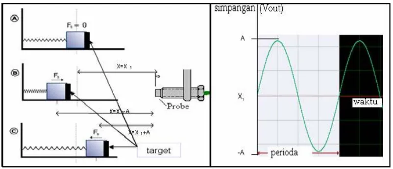
Sensor fluxgate bekerja dengan cara membangkitkan medan magnet untuk dirinya sendiri sebagai medan magnet acuan, jika terdapat bahan magnet yang bergetar pada posisi
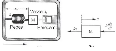
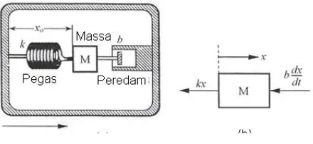
x maka sensor akan mendeteksi perubahan posisi (x) dari getaran tersebut melalui perubahan acuan medan magnetik pada intinya (Hendro, 2007). Perubahan posisi (x) dari benda yang bergetar terhadap sensor disebut dengan simpangan, simpangan maksimum disebut dengan amplitudo (A). Untuk meninjau konsep mekanik sebuah benda bergetar dimodelkan seperti Gambar 2.
Sebuah benda dengan beban bermassa M terikat pada sebuah pegas dengan konstanta pegas k dan massa yang bergerak diredam oleh peredam dengan koefisien redaman b seperti gambar (A). Beban bisa bergeser sejauhx dari titik setimbang terhadap sensor dengan arah horizontal. Selama bergerak percepatan beban M bergetar sebesar
, dan sinyal keluaran sebanding dengan defleksi x0dari beban M.
Gambar 2. Model Makanik Sensor Getaran (a), Diagram bebas dari massa (b). Berdasarkan tinjauan diagram bebas masaa M seperti gambar (B) dan menerapkan Hukum kedua Newton, memberikan :
Persamaan (6) merupakan persamaan diffrensial orde dengan keluaran percepatan berbentuk osilasi. Untuk menyelesaikan persamaan (5) digunakan Transformasi Laplace
(Boas, L.M, 1984).Berdasarkan TransformasiLaplacedidapatkan : )
ϖ mempresentasikan frekuensi anguler alami percepatan dan ξ koefisien normalisasi redaman. Misalkan
Dengan menggunakan teorema konvolusi transformasi Laplace dapat ditulis:
Persamaan (12) menunjukkan bahwa perubahan jarak atau simpangan benda berosilasi bergantung pada waktu t. Perubahan posisi atau jarak antara beban M (target) dengan sensor akan menyebabkan perubahan intensitas medan magnet yang diterima oleh sensor. Prinsip kerja pengukuran getaran berdasarkan perubahan posisi ini telihat pada Gambar 3.
Gambar 3. Prinsip Kerja SensorFluxgate Sebagai Sensor Getaran
Objek yang bergetar (target) dipilih yang bersifat magnetik. Material magnetik dapat berasal dari magnet permanen atau material ferromagnetik. Material magnetik ditempatkan pada objek yang akan diukur getaranya. Jika objek bergerak mendekati atau menjauhi detektor, maka medan magnetik disekitar titik setimbang akan mengalami
perubahan, perubahan ini disebut fluk magnetik (Φ). Perubahan fluk magnetik bergantung
pada posisi sensor terhadap objek.
Aplikasi fluxgate terhadap getaran dilakukan dengan cara menempatkan fluxgate
berdekatan objek yang bergetar, tetapi posisi sensor ini tidak bersentuhan dengan objek yang bergetar. Getaran akan menyebabkan perubahan jarak antara target pada ujung penggetar dengan sebuah titik didepannya. Pada kasus ini sebuah sensor diletakkan berhadapan dengan ujung penggetar (target) tampak seperti pada Gambar 4.
Ketika terjadi getaran, maka target yang berada diujung penggetar akan ikut bergetar. Hal ini akan berakibat pada jarak antara target dengan sensor akan mengalami perubahan. Fluxgate akan memancarkan medan magnet dari kumparan eksitasi. Medan magnet yang dipancarkan sebagian akan mengenai target yang merupakan bahan feromagnetik. Medan ini akan diubah menjadi arus induksi sebelum kemudian diubah lagi menjadi medan magnet induksi. Medan magnet yang diterima maupun yang dihasilkan akan mengalami perubahan ketika tejadi perubahan jarak. Medan magnet yang dihasilkan oleh target ini nantinya akan disuperposisikan dengan medan magnet referensi. Hasil superposisi tersebut akan diubah menjadi ggl induksi oleh kumparan pick-up. Karena besarnya intensitas medan magnet yang diterima oleh sensor berubah terhadap jarak maka perubahan amplitudo getaran yang terjadi akan berakibat pada perubahan tegangan yang dihasilkan oleh sensor. Ini berarti bahwa ggl yang terjadi merupakan fungsi jarak antara sensor dengan target (V(x)).
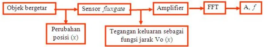
Sinyal getaran yang keluar dari sistem pengolah sinyal merupakan sinyal analog. Sinyal ini merupakan tegangan keluaran sebagai fungsi dari waktu. Tegangan keluaran sensor fluxgate berbanding lurus dengan posisi benda sehingga dengan melakukan Transformasi Fourier frekuensi dan amplitudo getaran dapat langsung diketahui.
C. Hasil-hasil Penelitian Sebelumnya Yang Berkaitan dengan Fluxgate
keberhasilan dalam pembuatan sensor getaran berbasisfluxgate. Hasil studi awal terhadap getaran dalam skala lab telah diproleh dengan rentangan kerja frekeuensi 55 sampai 300 Hz, tetapi pengukuran terhadap amplitudo belum diperoleh (Djamal, M., dkk., 2008). Berikut beberapa publikasi yang berkaitan dengan hasil-hasil sebelumnya.
1. Yulkifli, Mitra Djamal, Khairurrijal, Deddy Kurniadi, Pavel Ripka: The Influence of the Tape-core Layer Number of Fluxgate Sensor Using the Double Pick-up Coils to the Demagnetization Factor, Proc. ICICI-BME, November, 23-25, 2009, Bandung.(IEEE Xplore, 18 Februari 2010).
2. Yulkifli, Mitra Djamal, Khairurrijal, Deddy Kurniadi, Pavel Ripka: Demagnetization Factor of a Fluxgate Sensor Using Double Pick-up Coils Configurations. Proc. of The 3rd Asian Physics Symposium (APS) July 22–23, 2009, Bandung, Indonesia.
3. Yulkifli, Anwar, Z., Djamal, M. 2009: Desain Alat Hitung Kecepatan Sudut Berbasis Sensor Mangetik Fluxgate. Jurnal Sainstek Vol 1 No 2, pp. 79-90, Indonesia.
4. Yulkifli, Rahmondia N. S., Zul Azhar, Mitra Djamal, Khairurrijal, 2008: Desain Elemen Sensor Fluxgate Menggunakan Kumparan Sekunder Ganda Untuk Meningkatkan Resolusi Sensor , SNF HFI, Bandung Indonesia
5. Yulkifli, Suyatno , Rahmondia N. Setiadi Mitra Djamal, 2007: Linieritas Tegangan Keluaran Sensor Magnetik Fluxgate Menggunakan Elemen Sensor Multi-core, Jurnal Sains & Materi Indonesia, BATAN
6. Yulkifli, Rahmondia Nanda S., Suyatno, Mitra Djamal, 2007: Designing and Making of Fluxgate Sensor with Multi-Core Structure for Measuring of Proximity, Proc. CSSI Serpong- Indonesia.
7. Yulkifli, Rahmondia N. S., Mitra Djamal, Khairurrijal, Deddy Kurniadi, 2007: The Influences of Ferromagnetic cores, Pick-up Coil Winding Numbers, and Environmental Temperature to the Output Signal of a Fluxgate Magnetic Sensor, Jurnal Indonesian Journal Physics. Vol 18. No. 3.
III. METODE PENELITIAN
Metoda/rancangan yang digunakan dalam penelitian ini berupa eksperimen murni. Penelitian ini direncanakan akan dilakukan secara bertahap, yang meliputi: tahap pertama: pemilihan sensor magnetik yang cocok untuk menghasilkan frekuensi rendah, pembuatan rangkaian pengolah sinyal (RPS) dan interfacing. Tahap kedua: desain dan pembuatan prototip sensor getaran, Kalibrasi dan pengujian karakteristik sensor terhadap sumber pengetar, dan aplikasi pada getaran dengan simulasi getaran gempa.
Model desain sensor getaran berbasis fluxgate yang akan dikembangkan ditunjukkan Gambar 5.
Gambar 5. Model desain sensor getaran frekuensi rendah berbasis sensor magnetik
BAB IV. HASIL DAN PEMBAHASAN
Pada bagian ini akan dibahas tentang perkembangan hasil penelitian. Sesuai dengan tujuan dan tahapan penelitian ini maka dapat dilaporkan hal-hal sebagai berikut:
1. Tahap pertama, pembuatan elemen sensor fluxgate
Pada tahap ini sudah selesai dibuat elemen sensor fluxgate dan sistem elektronikanya.
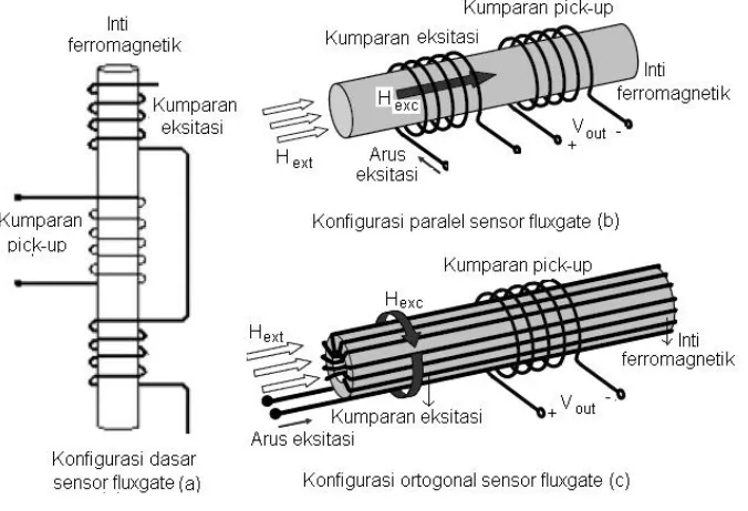
Elemen sensor fluxgate terdiri dari kumparan primer (excitation coil), kumparan sekunder (pick-up coil) dan inti ferromagnetik (core), seperti ditunjukkan Gambar (1a). Berdasarkan arah medan eksitasi yang dihasilkan oleh kumparan eksitasi, maka elemen sensor fluxgate terdiri dari dua, yaitu: sensor fluxgate orthogonal: arah medan eksitasi tegak lurus arah medan eksternal yang di ukur, dan sensor fluxgate paralel: arah medan medan eksitasi sejajar dengan medan eksternal yang diukur, seperti ditunjukkan Gambar (1b) dan (1c).
Gambar 1. Konfigurasi dasar kumparan elemen sensorfluxgate(a), Konfigurasi parallel sensorfluxgate(b), dan Konfigurasi orthogonal elemen sensorfluxgate(Zorlu, 2008).
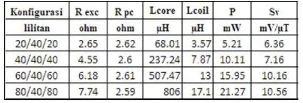
Karakteristik pengukuran untuk kedua konfigurasi lilitan eksitasi dan pick-up terlihat pada Tabel 1. Dan Tabel 2.
Tabel 1. Parameter dan karakteristik pengukuran konfigurasi lilitan eksitasi
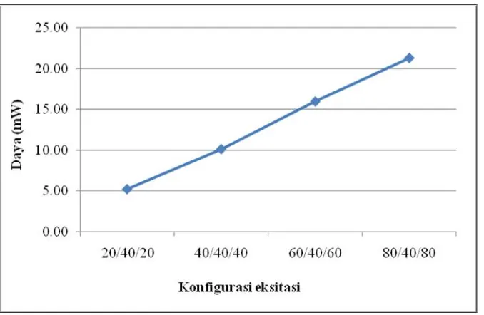
Ke empat konfigurasi di tinjau pengaruh terhadap daya eksitasi (P), dan sensitivity (Sv) dengan jumlah inti (ncore) sebanyak 4 lapis dan jumlah lilitan pick-up (Npc) 40 lilitan di buat konstan.
Tabel 2. Parameter dan hasil pengukuran variasi lilitan pick-up
Gambar 2.Hubungan konfigurasi lilitan (Nexc) dengan daya eksitasi (Pexc)
Hubungan sensitivtias dengan jumlah lilitan eksitasi ditunjukan pada Gambar 3. Pada gambar 3 terlihat perubahan sensitivity juga tidak terlalu besar.
Gambar 3.Hubungan konfigurasi lilitan (Nexc) dengan Sv
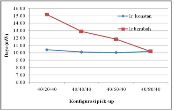
2.3 cm sedangkan yang lainya, lc berubah mengikuti konfigurasi lilitan pick-up masing-masing. Keseluruhan konfigurasi menggunakan jumlah lapisan inti (ncore) sebanyak 4 lapis dan eksitasi (Nexc) 40 lilitan. Hubungan jumlah lilitan pick-up dengan daya eksitasi untuk panjang sensor berbeda ditunjukkan Gambar 4.
Gambar 4.Hubungan konfigurasi lilitan pick-up denganPexc
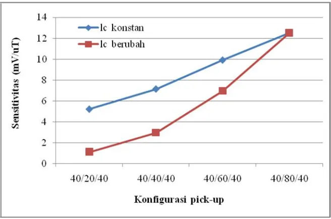
Gambar 5. Hubungan konfigurasi pick-up dengan sensitivitas.
2. Tahap Kedua, aplikasi elemen sensor fluxgate untuk getaran rendah
Pada tahap ini adalah pembuatan prototipe sensor getaran berbasis fluxgate. Akan dilakukan pengukuran terhadap getaran rendah (<10 Hz). Pada tahap ini terdapat kendala dalam hal sumber pengetar frekuensi rendah, sehingga kesulitan dalam mekalibrasi dan melakukan pengukuran getaran rendah. Berikutnya akan dirancang sebuah alat pemicu getaran rendah dengan menggunakan sensor autocoupler dan diintegrasikan dengan sensor fluxgate.
Sensorfluxgate bekerja dengan cara membangkitkan medan magnet untuk dirinya sendiri sebagai medan magnet acuan, jika terdapat bahan magnet yang bergetar pada posisi xmaka sensor akan mendeteksi perubahan posisi (x) dari getaran tersebut melalui perubahan acuan medan magnetik pada intinya (Hendro, 2007). Perubahan posisi (x) dari benda yang bergetar terhadap sensor disebut dengan simpangan, simpangan maksimum disebut dengan amplitudo (A). Untuk meninjau konsep mekanik sebuah benda bergetar dimodelkan seperti Gambar 6. Sebuah benda dengan beban bermassa M terikat pada sebuah pegas dengan konstanta pegas k dan massa yang bergerak diredam oleh peredam dengan koefisien redaman b seperti gambar (A). Beban bisa bergeser sejauh x dari titik setimbang terhadap sensor dengan arah horizontal. Selama bergerak percepatan beban M bergetar sebesar
2 2
dt x d
Gambar 6. Model Makanik Sensor Getaran (a), Diagram bebas dari massa (b).
Berdasarkan tinjauan diagram bebas masaa M seperti gambar (B) dan menerapkan Hukum kedua Newton, memberikan :
dengan f adalah percepatan dari massa relatif dari bumi persamaan (4) dapat ditulis mejadi (5) :
Persamaan (6) merupakan persamaan diffrensial orde dengan keluaran percepatan berbentuk osilasi. Untuk menyelesaikan persamaan (5) digunakan Transformasi Laplace
(Boas, L.M, 1984).Berdasarkan TransformasiLaplacedidapatkan : )
ϖ mempresentasikan frekuensi anguler alami percepatan dan ξ koefisien normalisasi
)}
Dengan menggunakan teorema konvolusi transformasi Laplace dapat ditulis:
dimana a adalah impulse bergantung pada percepatan dan g(t) adalah inverse transform )}
Persamaan (12) menunjukkan bahwa perubahan jarak atau simpangan benda berosilasi bergantung pada waktu t. Perubahan posisi atau jarak antara beban M (target) dengan sensor akan menyebabkan perubahan intensitas medan magnet yang diterima oleh sensor. Prinsip kerja pengukuran getaran berdasarkan perubahan posisi ini telihat pada Gambar 7.
Gambar 7. Prinsip Kerja SensorFluxgate Sebagai Sensor Getaran
Objek yang bergetar (target) dipilih yang bersifat magnetik. Material magnetik dapat berasal dari magnet permanen atau material ferromagnetik. Material magnetik ditempatkan pada objek yang akan diukur getaranya. Jika objek bergerak mendekati atau menjauhi detektor, maka medan magnetik disekitar titik setimbang akan mengalami
perubahan, perubahan ini disebut fluk magnetik (Φ). Perubahan fluk magnetik bergantung
Aplikasi fluxgate terhadap getaran dilakukan dengan cara menempatkan fluxgate
berdekatan objek yang bergetar, tetapi posisi sensor ini tidak bersentuhan dengan objek yang bergetar. Getaran akan menyebabkan perubahan jarak antara target pada ujung penggetar dengan sebuah titik didepannya. Pada kasus ini sebuah sensor diletakkan berhadapan dengan ujung penggetar (target) tampak seperti pada Gambar 8.
Gambar 8. Prinsip kerjafluxgatesebagai sensor getaran.
Ketika terjadi getaran, maka target yang berada diujung penggetar akan ikut bergetar. Hal ini akan berakibat pada jarak antara target dengan sensor akan mengalami perubahan. Fluxgate akan memancarkan medan magnet dari kumparan eksitasi. Medan magnet yang dipancarkan sebagian akan mengenai target yang merupakan bahan feromagnetik. Medan ini akan diubah menjadi arus induksi sebelum kemudian diubah lagi menjadi medan magnet induksi. Medan magnet yang diterima maupun yang dihasilkan akan mengalami perubahan ketika tejadi perubahan jarak. Medan magnet yang dihasilkan oleh target ini nantinya akan disuperposisikan dengan medan magnet referensi. Hasil superposisi tersebut akan diubah menjadi ggl induksi oleh kumparan pick-up. Karena besarnya intensitas medan magnet yang diterima oleh sensor berubah terhadap jarak maka perubahan amplitudo getaran yang terjadi akan berakibat pada perubahan tegangan yang dihasilkan oleh sensor. Ini berarti bahwa ggl yang terjadi merupakan fungsi jarak antara sensor dengan target (V(x)).
Perancangan sistem alat ukur frekuensi rendah menggunakan sensor optocoupler memiliki batasan-batasan tertentu bergantung kepada komponen dan bahan yang digunakan. Komponen yang digunakan meliputi motor DC yang berperan sebagai actuator, yaitu suatu piranti yang mengubah sinyal listrik menjadi gerakan mekanik. Alat ukur frekuensi rendah ini dirancang bisa menghasilkan data yang akurat, sehingga harus memenuhi speseifikasi tertentu. Spesifikasi merupakan pendeskripsian secara mendetail produk hasil penelitian. Secara umum ada dua tipe spesifikasi yaitu spesifikasi performansi dan spesifikasi desain. Spesifikasi performansi mengidentifikasi fungsi-fungsi dari setiap komponen pembentuk sistem, sedangkan spesifikasi performansi biasa disebut juga dengan spesifikasi fungsional.
Adapun rancangan sistem alat ukur frekuensi rendah menggunakan sensor optocoupler dapat dilihat pada Gambar 8
Gambar 1. Desain alat ukur frekuensi rendah menggunakan sensor Autocoupler
Berdasarkan pengukuran dan analisis data pengukuran diperoleh data-data sebagai berikut:
1. Pengukuran dengan frekuensi keluaran 0.20 Hz
Gambar xx. Bentuk grafik keluaran frekuensi getaran 0,20 Hz 2. Pengukuran dengan frekuensi keluaran 0.40~( 0.38) Hz
3. Pengukuran dengan frekuensi keluaran 0.60 Hz
Gambar xx. Bentuk grafik keluaran frekuensi getaran 0,60 Hz
4. Pengukuran dengan frekuensi keluaran 0.80 ~ (0.77) Hz
5. Pengukuran dengan frekuensi keluaran 1.00 ~(0.98) Hz
Gambar xx. Bentuk grafik keluaran frekuensi getaran 1.0 Hz
Data perbandingan antara pengukuran standar (keluaran dari LCD) dan pengukuran getaran dengan menggunakan sensor fluxgate dapat terlihat pada Gambar YY
Berdasarkan teori kesalahan pengukuran maka di dibandiingkan dengan data kalibrator. Kalibrator disini adalah berupa instrumen yang menghasilkan getaran dengan frekuensi rendah. Kesalahan pengukuran diolah menggunakan persamaan regresi liner yang diperoleh dari perbandingan frekuensi sumber dan frekuensi terukur, dimana
hubungan ini dinyatakan pada persamaan (…) adalah:
ft=0.367(fs)3-0.668(fs)2+1.386(fs)-0.060 Keterangan
ft= frekuensi terukur
fs= frekuensi sumber ,
Data kesalahan pengukuran dapat terlihat pada Tabel xxx::
Tabel xxx.. Kasalahan absolute dan relative pengukuran getaran
Frekuensi frekeunsi Kesalahan Pengukuran
LCD PC equation Absolut (Hz) Relatif (%)
0.95 0.93 0.946425819 -0.00357418 -0.27706829 0.9 0.89 0.903140823 0.003140823 0.243474651 0.86 0.85 0.860853875 0.000853875 0.06619186 0.83 0.83 0.840040629 0.010040629 0.778343333 0.8 0.78 0.788829384 -0.01117062 -0.86593922 0.76 0.75 0.758578125 -0.00142188 -0.11022287 0.74 0.73 0.738572039 -0.00142796 -0.11069465 0.71 0.69 0.698868003 -0.011132 -0.8629455 0.68 0.68 0.688993344 0.008993344 0.69715845 0.62 0.61 0.620199227 0.000199227 0.015443953
0.6 0.6 0.610392 0.010392 0.805581395
0.55 0.54 0.551440488 0.001440488 0.111665736 0.5 0.48 0.491960064 -0.00803994 -0.62325085 0.46 0.46 0.471933512 0.011933512 0.92507845 0.43 0.41 0.421263207 -0.00873679 -0.67727078 0.4 0.38 0.390358824 -0.00964118 -0.74737798 0.37 0.36 0.369509952 -0.00049005 -0.03798822 0.36 0.36 0.369509952 0.009509952 0.737205581 0.32 0.32 0.327142656 0.007142656 0.553694264
0.31 0.3 0.305589 -0.004411 -0.34193798
Untuk lebih jelasnya, kesalahan absolute dan kesalahan relative pengukuran getaran frekeunsi rendah dapat terlihat pada Gambar TT dan PP.
Gambar TT. Grafik kesalahan relatif pengkuran getaran rendah
Gambar PP. Grafik kesalahan absolut pengkuran getaran rendah
BAB V. KESIMPULAN DAN SARAN A. Kesimpulan
Penggunaan sensor fluxgate sebagai alat ukur getaran sudah berhasil dibuat. Penggunaan fluxgate untuk sensor getaran merupakan bagian lain dari aplikasi sensor fluxgate yang telah penulis kembangkan semenjak 2008-sekarang. Berdasarkan hasil dan pembahasan untuk aplikasi terhadap getaran khsusnya getaran rendah dapat diambil beberapa kesimpulan, yaitu:
1. Sensor fluxgate dapat digunakan sebagai alat ukur getaran frekuensi rendah
2. Daerah pengukuran berkisar dari 0.2 sampai 1.2 Hz. Batas pengukuran ini terkendala oleh alat kalibrator yang hanya dapat menghasilkan frekeunsi maksimal sekitas 1.2 Hz.
3. Kesalahan absolute dan relative pengukuran frekuensi getaran rendah berturut-turut adalah 0,02 Hz dan 0.24 %.
B. Saran
DAFTAR PUSTAKA
Azhar, D., Jusan Q., Parsaulian S., 2006: Analisis kerja ”Vibration Monitor” Bently Nevada tipe
5250,Proceding SIBF, Bandung 31 Agustus 2006
Azhar, Z., Yulkifli,Rahmondia. N.S. Mitra Djamal, 2008: Desain Awal Prototip Magnetometer Untuk Mengukur Medan Magnet Dalam Ruang 3 Dimensi. Posiding SIBF Tgl. 28 Agustus, ITB Bandung
Caruso, M.J, Tamara B., 1998: A New Perspective on Magnetic Field Sensing,Sensor Magnazine, Magnetic Sensor, Tersedia diwww.ssec.honeywell.com. 2007.
Corres, J.M., Javier B, Fransisco J.A, Ignacio R.M, 2006: Vibration monitoring in Elctical Engines Using an in-line Fiber Etation,J. Sensor and Actuator,132, pp. 506-516.
Djamal, M., 2007: Sensor Magnetik Fluxgate dan Aplkasinya untuk Pengukuran Kuat Arus , J. Sains dan Teknologi Nuklir Indonesia,III, pp. 51-69
Djamal, M., Yulkifli, Agung Setiadi, Rahmondia N.Setiadi 2009: Desain Awal Elemen Sensor Fluxgate Berbasis Teknologi Printed Circuit Booards (PCB), disampaikan pada SNBM, 26 November Batan, Serpong. Diterbitkan pada Jurnal Sains Materi Indonesia (JUSAMI) (Inpress).
Djamal, M., Yulkifli:FluxgateSensor and Its Application, Proc. ICICI-BME, November, 23-25, 2009, Bandung.(IEEE Xplore, 18 Februari 2010).
Fraden, J., 1996:Handbook of Modern Sensor.New York, Springer-Verlag New York, Inc.
Göpel, W., et al., 1989: Sensors, A Comprehensive Survey, Magnetic Sensors, VCH Publishers Inc., Suite.
Hendro, dkk., 2007: Pembuatan Sensor Getaran Berbasis Fluxgate, Berita Utama LPM ITB, edisi khusus April 2007.
Hufri, Yulkifli, 2009: Sensor MagnetikFluxgate Menggunakan Kumparan Pick-up Ganda, diterbitkan di Jurnal Invotek , FT Univ. Negeri Padang .
Intechno:’Sensor Market 2008”, Intechno Consulting, Basle, Switzerland, 05.1999
Kaluza, F., Angelika Gruger, Heinrich Gruger, 2003: New and Future Applications pf Flxgate Sensors,Sensor and Actuator,106, pp. 48-51.
Kawahito, S., Y. Tadakoro, 1996: High-Performance Micro Fluxgate Magnetics Sensors,
International Conference on Microelectronics ICME, H.R , P. 85-89., 16-17 Januari Bandung, Indonesia
Liu, S., 2006,: Studi on the low power consumption racetrack fluxgate, J. Sensor and Actuator,
130, pp. 124-128.
Ripka, P., 2001:Mangetic Sensor and Magnetometers, Artec House.
Ripka, P., 2003: Advances influxgateSensor,J. Sens. and Actuators A, Vol.106, pp. 8-14.
Ripka, P., 2008: Sensors based on bulk soft magnetic materials:Advances and challenges Journal of Magnetism and Magnetic Materials320 , pp. 2466–2473
Smith, C.H, Robert Scheneider, 1998: A New Perspective on Magnetic Field Sensing, Sensor Magnazine, Magnetic Sensor, Tersedia diwww.nve.com. 2007.
Yulkifli, Suyatno , Rahmondia N. Setiadi Mitra Djamal, 2007a: Linieritas Tegangan Keluaran Sensor Magnetik Fluxgate Menggunakan Elemen Sensor Multi-core.
Jurnal Sains & Materi Indonesia, BATAN
Yulkifli, Rahmondia Nanda S., Suyatno, Mitra Djamal, 2007b: Designing and Making of
Fluxgate Sensor with Multi-Core Structure for Measuring of Proximity, Proc. CSSI 2007, Serpong Tanggerang- Indonesia.
Yulkifli, Rahmondia N. S., Mitra Djamal, Khairurrijal, Deddy Kurniadi, 2007c: The Influences of Ferromagnetic cores, Pick-up Coil Winding Numbers, and Environmental Temperature to the Output Signal of a Fluxgate Magnetic Sensor
Yulkifli, Rahmondia N. S., Zul Azhar, Mitra Djamal, Khairurrijal, 2008: Desain Elemen Sensor Fluxgate Menggunakan Kumparan Sekunder Ganda Untuk Meningkatkan Resolusi Sensor ,prosiding SNF HFI, Bandung Indonesia
Yulkifli, Anwar, Z., Djamal, M. 2009a: Desain Alat Hitung Kecepatan Sudut Berbasis Sensor MangetikFluxgate. Jurnal SainstekVol 1 No 2, pp. 79-90, Indonesia. Yulkifli,, Mitra Djamal, Khairurrijal, Deddy Kurniadi, Pavel Ripka: Demagnetization Factor
of aFluxgateSensor Using Double Pick-up Coils Configurations.Procd. of The 3rd Asian Physics Symposium(APS) July 22 – 23, 2009, Bandung, Indonesia.
Draf publikasi: Journal of Civil Engineering of science (JCES)
Development of Fluxgate Sensors and Its
Applications on Civil Engineering
Yulkifli, Mitra Djamal, Asrizal
Department of Physics, Universitas Negeri Padang, Padang, Indonesia [email protected])
Abstract- The fluxgate element is a low field magnetic sensor. Because the magnetic field strenght of a position is a function of its distance to the magnetic source, so the magnetic field strenght of a position can be used for determining its distance to the magnetic source. Fluxgate sensors were firstly developed in the 1930 and were rapidly used for many of applications. These sensors have been used in robotic space probes to analyze, map and monitor the Earth's magnetic field and the other planets. They are also used in geological, aerospace, underwater navigation, land navigation and submarine detection. The future development of fluxgate is reducing their size and making them compatible with micro/nano-electronic technology. In this paper, we give a reviews recent development in the manufacturing technology and applications offluxgate sensors, specially:the fluxgate element is used to measure the position of a vibrating object as a function of time. The developed sensor has natural frequency about 38 Hz. At the region between 25 Hz –36 Hz, the vibration sensor has 59.25 mV/g sensitivity.
Keyword: Fluxgate sensor,magnetic sensor, Magnetometer, Pick-Up coi,vibrating, frequency
I. INTRODUCTION
Fluxgate sensor is one of magnetic sensor that still attracts the attention of many researchers. This is caused by advantages of fluxgate sensor which is more sensitive [1,2,3] and more precise [4]. Fluxgate has been used as magnetic sensors since the 1930's [5]. Trend of the development of fluxgate is to reduce their size and to have better manufacturing technology. Reducing the size and weight of fluxgate sensors is essential in microelectronics industry.
Formerly, the use of fluxgate sensor is quite limited only to detect and measure magnetic fields with low frequencies. With the tremendous development of fluxgate, the sensor can measure magnetic fields as weak as Earth's magnetic field (±
45 μ T) [6]. Nowadays, fluxgate sensors have been developed
as an instrument of geophysics, detection of ferromagnetic objects [7], the space instruments [8], and the instrument bio-magnetic [9]. At space application, the fluxgates are used as payloads of satellites for the in-orbit measurement of the Earth magnetic field, for navigation and for measurement of interplanetary magnetic fields.
Resolution and precision of fluxgate sensors has also been improved. In 2003, as reported by Ripka [10], a resolution of 100 pT and precision of 10 nT in commercial devices can be improved to achieve a resolution of 10 pT and the precision of 1 nT. In addition, the sensitivity of fluxgate is also increased.
Recently, Janosek and Ripka [3], reported a sensitivity of fluxgate sensor reaches 120.000 V/T using PCB technology by controlling the excitation current. Ripka et al [11] reported a sensitivity of fluxgate sensor for 30 mV/μ T using multi wire core. Today, their sensitivity spans a wide range from 10-10 to
10-4T.
The working principle of a fluxgate sensor is based on non-linear properties of ferromagnetic materials, where its permeability changes by a change of magnetic field around the sensor [12]. Magnetic field strength measurements are based on the relationship between magnetic field strength H against magnetic field inducedB. IfBis generated from the inputHof the wave pulse back and forth, then in a state of saturation at the output ofB will occur even and odd numbered harmonic wave. In the even-numbered harmonic wave there is a second harmonic wave, which is proportional to the external magnetic field. The direction of this wave is in the direction of the external magnetic field [13,14,15].
In this paper, we review a recent development of fluxgate sensors, including manufacturing technology and their applications.
II. THEORETICAL BACKGROUND
The fundamental principle of functional fluxgate system is the ratio of the external magnetic field (Bext) as measured and
reference magnetic field (Bref) [16]. Changing the magnetic
field strength into electrical signals can be done directly to measure Bext. Fluxgate magnetic sensor does not use a direct
way, but uses a reference magnetic field Bref for comparison
with the measured magnetic field Bext using containers filled
with core material. This principle is shown in Fig. 1.
Fig. 1. Magnetic field measurement principle: a) straightforward; b) using Bref
reference magnetic field Brefas comparator for measured magnetic field Bext
Fluxgate element consists of ferromagnetic core and two coils consist of excitation and pick-ups coils. Excitation coil is a coil that is used to generate the excitation magnetic field. The excitation coil is the same as in the solenoid, where the magnetic field arising from the presence of electric field (Faraday's law).
A good coil configuration will increase the accuracy because the measured field will be not distorted that come from the core. For more details, working principles of fluxgate measurements can be seen in Fig. 2.
Working principle of fluxgate magnetic sensor; (a) Field of excitation without external magnetic field Bext = 0, (b)
excitation field with the external magnetic field Bext≠ 0, (c) in
a state of saturation magnetization curve in Bext = 0; (d) in a
state of saturation magnetization curve in Bext≠ 0; (e) changes
in flux with time at Bext= 0; (f) change in flux with time at Bext
≠ 0; g) sensor output voltage at Bext= 0; (h) The sensor output
voltage at Bext≠ 0.
Fig. 2. Fluxgate working principle ( adapted from [17]).
Figure 2 shows that the fluxgate sensor works based on the differential principle. The interference/noise from environment such as temperature or other environmental influences will eliminate each other and the sensor can measure extremely weak magnetic fields. To overcome the interference of high frequency signals, sensors mounted on a second order low pass filter. The detection of the second harmonic component of the sensor output voltage is performed by means of a phase has undergone significant developments both in technology manufacture such as: fluxgate element, signal processing circuit, model of geometry, and its applications. Various technological approaches to improve the performance of fluxgate such as: sensitivity, accuracy, resolution, field strength and homogenity have been carried out. A technological approach has been developed to optimize the fluxgate.
A. Conventional Technology
In conventional technology, wire of core excitation and pick-up coil are wrapped manually. Metglass or Vitrovac in ribbon-shaped with a width and thickness of mm scale is normally used as the ferromagnetic core. Two cores consisting of three layers tape of Vitrovac/Metglas are stacked parallel thus increasing the core thickness. After coated with an insulator the core is wrapped by winding wire. Winding wire is composed for excitation and the pick-up coil. Winding excitation is located at the edge of the flanking secondary winding or pick-ups.
The number of windings is inversely proportional to the sensitivity of the sensor. So that it only takes little windings to get high sensitivity. The often used shapes of ferromagnetic core of fluxgate element are single-core rod, double rod-core, ring-core-core and racetrack. [4, 18, 19]. Fig. 2 shows a design of fluxgate using conventional technology.
Fig.2. Geometry of fluxgate sensor: (a) monopick-up and (b) doublepick-up
[20]
B. PCBs Technology
PCBs technologies developed since 1999 at the Switzerland by the group of Prof. Martin. A.M. Gijs at Ecole Polytechnique Fédérale de Lausanne. They proposed the use of Printed Circuit Board (PCB) Technology for the planarization and integration of fluxgate sensors [22]. Furthermore, they developed of PCBs technology with three layers in 2000 by using amorphous magnetic core. The sensor has a permeability of 100,000 and a sensitivity of 18 V/T at a frequency of 10 kHz [23].
Then, PCBs technologies was developed at the Univ. Complutense de Madrid and Madrid Polytechnical University (Spain) by Perez, L. et.al., which combines technology with the electrodeposition PCBs in 2004. These sensors integrate the excitation coil and ferromagnetic core using amorphous ferromagnetic materials Co-P. These sensors have high sensitivity around 160 V/T with a linear range (0-250 μ T)[24].
Lucas, et al (2006) reported a fluxgate sensor based on multilayered Co-P alloy as ferromagnetic core. They obtained that coercivity at high frequency is only due to eddy currents [25]. PCBs technology has a simple process and relatively inexpensive. But the disadvantage is a larger size compared with conventional technology, especially when compared with micro technology. Manufacturing process of fluxgate sensor with PCBs technology are shown in Fig. 3.
(Four layer, Single pick up, Core: Vitrovac VC 6025Z and sensor size = 8,7 x 2,5 x 0,5 cm).
Sensor fluxgate is characterized using Fluke 5500 calibrator as generator of the current and the solenoid as generator of the magnetic field. Set-up of sensor response measurement is shown figure 3.(b).
(a)
(b)
Fig.3. Schematic diagram of fluxgate fabrication process; (a) Design of PCB fluxgate sensor element, (b) Set-up of sensor response measurement from
external magnetic field [26].
C. Microfabrication
Wire as a material excitation and pick-up coil as well as the ferromagnetic core made using a variety of micro technology process. The micro technology including among others: electroplating, chemical etching, flex-foil, photolithography, photoresist and evaporation. Some of the researchers who developed this technology are Kawahito, et al (1994) [27] and (1996) [28], Ripka, et al. (2001) [29, 30], Wang, et al., (2006) [31], Fan., et al. (2006) [32] and Zorlu, et al. (2008) [19].
Park, et.al [33], has reported the fabrication of fluxgate sensor with magnetic core from electroplated Ni0.81Fe0.19under
external magnetic field 2000 G. They obtain the permeability of fluxgate sensor is 1250 and have a linier response between −100 to +100T then sensitivity 210 V/T. Baschirotto, et.al [34], has been using sputtering deposition for microfabrication of fluxgate. They showed that the magnetic properties of the core, has decreased after the deposition. Sensitivity of sensor are 0.45 mV/T and linearity about 1.15% at scale ± 50 T.
Zorlu, et.al [35], has been developed a micro technology using electroplating and photoresist. They obtain sensitivity of sensor with 18 cascaded cores are 623 μ V/mT and linier range
about ±300 μ T.Micro technology has a very complex process
so that the cost of the manufacturing process is relative expensive. In addition the resulting sensitivity is quite low due to small cross-sectional area. To obtain high sensitivity required of high frequency, and limitations of coils number in the solenoid [36,37].
According to Ripka [38], the use of ferromagnetic core in the form of bulk soft magnetic core is better than thin films core, because the large magnetic field measured depends on the cross-sectional area of the core. Kubik, et al [12] obtain that the
sensor the micro technology process has a big noise compared to the PCBs technology.
D. Hybrid Technology
The combination of the above technologies is called the hybrid technology [39]. Manufacturing process of fluxgate sensor with hybrid technology is shown in Fig. 4. Several researchers that use this hybrid technology are: Belloy, et al [40], Tipek, et al [41] and Perez, et al [42].
Fig.4. Schematic of the fabrication process.(modified from L. Perez., 2004)[42]
Tipek, et.al [43] reported a preparation of the sensor by PCB technology with ring-shaped core made with electrodeposited. The resulting sensor has a sensitivity of 1800 V/T for pick-up coil unturned and 13 100 V/T for tuned pick-up coil at a frequency of 150 kHz. Perez et al [42] combined the PCB technology by electrodeposition to create a fluxgate sensor in 2004. They integrate the excitation coil and ferromagnetic core using amorphous ferromagnetic materials Co-P. This sensor has a high sensitivity about 160 V/T by linier range of 0-250 μ T.
In 2009, Kubik et al [44] using PCB technology and electroplated by developing multilayer material PCBs up to 12 layers. The resulting sensor has permeability 2300 at 50 kHz and sensitivity 90 V/T inxaxis and 112 V/T in yaxis, andz axis 198 V/T. The difference between the value of the sensitivity of the xand y-axis is caused by the anisotropy of core material, while the difference in thezaxis is caused by the demagnetization factor. Janosek et al [45], make a fluxgate sensor with the dual core lamination by race tracks and five-layer PCB. This sensor has a sensitivity of 615 V/T for 650mA peak-to-peak excitation current with non-linearity 0.5%.
IV. APPLICATIONS OF FLUXGATE SENSOR
A. Application to Measurement of Weak Magnetic Field
Fig. 6. Sensor output voltage as function of magnetic field
B. Application to a Proximity Sensor
Other application of the fluxgate is a proximity sensor [46]. Change the distance between the target with the sensor is inversely proportional to the output characteristic of the sensor. The farther from the target then the output voltage characteristics are smaller and vice versa. Fluxgate sensors have been developed capable to detect changes in the distance with a resolution of 10 μ m, the absolute error 0.12 μ m and relative error 2.5%.
C. Application to Vibration Sensor
Fluxgate elements have also been applied to the vibration sensor [47,48, 49]. The vibration from the source will vibrate the magnetic mass on cantilever. The systems vibration sensor consist of a seismic mass, spring and body shown in Fig. 7.
(a)
(b)
Fig. 7. Vibration model (a) and Design of the vibration sensor (b).
Magnetic mass is used because it can make significant changing to the magnetic field despite the position shift is small. Beam made from copper-beryllium alloy is used as cantilever. The distance between fluxgate sensor and magnetic mass are adjustable. This variety can be tuned according to the requirement of measurement. Magnetic shielding is used to avoid unwanted magnetic field that can disturbed measurement. The design of mechanical system of vibration measurement is shown in Fig. 8.
Fig. 8. The photo equipment of mechanical system vibration measurement
To calibrate the sensor, variety vibration frequency and acceleration is used. The calibrator is Bruel and Kjaer Exciter Control Type 1047. The acceleration is varied from 0.5 g to 2.5
g. g is acceleration unit (1 10 2
s m
g ) and the frequency is
varied from 25 to 48 Hz to explore natural frequency region. Measurement data is acquired using Multichannel Signal Analyzer (MSA). In the vibration measurements with the indirect technique the sensor output signal is depend on the mechanical vibration parameter which used such as length of arm (L), seismic mass of the object (m) and the sensor probe distance from vibration object (Δ x). Sensor design for measurement with L=5cm, m=0.28g and Δ x =2cm producing the resonance frequency around 38-40 Hz. Measurement result is represented by Fig 9.
Fig. 9. Measurement result around natural frequency at 1g acceleration.
This result is convenient to the theory that there is gain around natural frequency area. The gain is also proportional to the applied external force. To find the work range sensitivity of the vibration sensor, we use sensor modeling by mathematical approach. Based on the selected mathematical approaches model resulting the sensitivity value increase while frequency increase. Average sensitivity is 59.25 mV/g, The maximum absolute and relative errors are 15.5 mV and 4.39% respectively at 34 Hz [48,49]
D. Application to Angular Velocity
Fluxgate elements have been applied to measurement of angular velocity [50]. Fluxgate sensor placed at a distance of 1 cm and 2 cm of the magnetic disc. Magnetic disc rotated by a motor-DC. The results of measurements of the frequency and the current source are shown in Fig. 8. As seen in Fig. 8 the frequency response for the number of magnetic objects 2 and 4 higher than at 8 and 16. This is caused by the mass of the magnet attached to the disc. This angular velocity sensor has a relative error of less than 5%.
Fig. 8. Frequency curves of magnetic disc
E. Application to the Measure Current
One of the interesting applications of the magnetometer is to measure current [51]. On the PCB a stripe with 20-cm length is made for current flow. The magnetic sensor is put perpendicular to the stripe. Current from 0.1–1900 mA is flown on the PCB-stripe. Measurements are carried out for different distance, e.g. 4mm, 8mm, and 18mm. The measurement set-up is shown in Fig. 9. The sensor characteristic for small current (0-100mA) is shown in Fig. 10. It can be seen that there is a linear relationship between current and output signal.
Fig. 9. Set-up equipment for current measurement
R2 = 0.9998 R2
Fig. 10. Sensor output signal as functions of current
F. Application to the Displacement Measurement
Magnetic sensor offers a very attractive alternative for a non-contact displacement measurement [52]. The measurement system as shown Fig. 11. It gives more benefits in terms of cost, eases of deployment and maintenance, and enhanced measurement capabilities. By applying magnetic sensor, smaller displacement can be detected rather than the ordinary sensor. Besides that, this sensor is separated from the object (non contact measurement), so that it can avoid thermal and mechanical influence of object. The sensor that we developed can measure the distance from (0.5 - 17) mm with a relative error 1.23% [53].
Fig. 11. The measurement system of distance
IV. CONCLUSION
Since the 1930's, fluxgate sensors have undergone tremendous development, both in terms of manufacturing technology and its application. Nowadays, the research on fluxgate sensor is to minimize their size and make it compatible with micro-electronic technology. The fluxgate sensors have been used in robotic space probes to analyze, map and monitor the Earth's magnetic field and the other planets. They are also used in geological, aerospace, underwater navigation, land navigation and submarine detection.
ACKNOWLEDGEMENT
The work was supported by the Directorate of Higher Education, Indonesian Ministry of Education under grant
“Hibah Bersaing”No 243H/UN.35.2/PG/2012 controlled excitation,Sensors and Actuators A151, pp.141–144, 2009. [4]. P. Ripka (Ed), Magnetic sensors and magnetometers, Artech, London,
2001.
[5]. P. Ripka, Review of fluxgate sensors,Sensors and Actuators A33, pp.129-141, 1992.
[6]. F. Kaluza, A. Gruger and H. Gruger, New and future applications pf fluxgate sensors,Sensors and Actuators A,106. pp.48-51. 2003.
[7]. H.S. Park, J.S.Hwang, W.Y.Choi, D.S.Shima, K.W.Na, and S.O.Choi, Development of micro-fluxgatesensors with electroplated magnetic cores for electronic compass,Sensors and Actuators A,114, pp.224-229 .2004. [8]. M.H. Acuna, Space-based magentometers,Rev. Sci. Instrum.73(11). pp.
3717–3736, 2002.
[9]. P.Ripka and P. Navratil, Fluxgate sensor for magnetopneumometry,
Sensors and Actuators A,60, pp.76-79.1997.
[10]. P. Ripka, Advances in fluxgate sensors,Sensors and Actuators A,106, pp. 8-14, 2003.
[12]. J. Kubik, L. Pavel, and P. Ripka, PCB recetrack Fluxgate Sensor with Improved Temperatur Stability,Sensors and Actuators A,130, pp 184-188. 2006.
[13]. W. Gopel, J. Hesse, and J.N. Zemel, Sensors: A Comprehensive survey, magnetic sensors, VCH Publishers Inc, 1989.
[14]. S. Kawahito, H. Sato, M. Sutoh and Y. Tadokoro, High resolution mikrofluxgate sensing element using closely coupled coil structures,
Sensors and Actuators A,54, pp.612-617. 1996.
[15]. Hufri and Yulkifli, Sensor magnetic fluxgate menggunakan kumparan pick-ganda, Jurnal Invotex, Vol. X, No. 2.pp. 2517-2530, ISSN 1411-3411, 2009.
[16]. W. Göpel, J. Hesse, and J.N. Zemel, : Sensors, A Comprehensive Survey, Magnetic Sensors, VCH Publishers Inc., 1989.
[17]. H. Grueger, and R. Gottfried-Gottfried, “CMOS Integrated Two Axes Magnetic Field Sensors – Miniaturized Low Cost System With Large Temperature Range”, Fraunhofer Institute for Microelectronic Circuits and Systems IMS,” Preparation, Propoerties, and Applications of Thin Ferromagnetic Films, pp. 35-38, 2000.
[18].J. Kub´ık,PCB fluxgate sensors,Dissertation Thesis, CTU in Prague, pp. 56–58. 2006.
[19]. O. Zorlu, Orthogonal fluxgate type magnetic microsensor with wide linier operation range, Dissertation Thesis, EPFL Ankara, 2008.
[20]. Yulkifli, Mitra Djamal, Khairurrijal, Deddy Kurniadi, Pavel Ripka: The Influence of the Tape-core Layer Number of Fluxgate Sensor Using the Double Pick-up Coils to the Demagnetization Factor,Proc. ICICI-BME, November, 23-25, 2009, Bandung.
[21]. Ripka, P., 2001a: Mangetic Sensor and Magnetometers,Artec House
[22]. O. Dezuari, S.E, Gilbert, E. Belloy, M.A.M. Gijs, New hybrid technology for planar fluxgate sensor fabrication.IEEE. Trans Magn.35, pp.2111-2117. 1999.
[23]. Dezuari, O.; Gilbert, S.E.; Belloy, E.; Gijs, M.A.M. Printed circuit board integrated fluxgate sensor.Sensors and Actuator. A81, pp. 200-203. 2000. [24].L. Perez,, C. Aroca, P. Sánchez, E. López, M.C. Sánchez, Planar fluxgate
sensor with an electrodeposited amorphous core,Sensors and Actuators A
109pp. 208–211. 2004.
[25]. I. Lucas, L. Perez, M. Plaza, O. de Abril,and M.C. Sanchez, Pinning field and coercivity in CoP alloys.J. Magn. Magn. Mater.316, pp. 462-464. 2007.
[26].Yulkifli, Pengembangan Elemen Fluxgate dan Penggunaanya untuk Sensor-sensor Berbasis Magnetik dan Proksimiti, Disertasi, Institut Teknologi Bandung, 2010.
[27].Kawahito, S., Sasaki, Y., Sato, H., Nakamura, T. and Tadokoro, Y., A Fluxgate magnetic sensor with micro-selonoids and electroplated permalloy cores,J. Sensor and Actuator A, vol.A43, pp.128-134. 1994. [28]. Kawahito, S., Satoh, H., Sutoh, M. and Tadokoro, Y., High-resolution
microfluxgate sensing elements using closely coupled coil structures,
Sensor and Actuator A, vol.54, pp. 612-617, 1996.
[29]. Ripka, P., Kawahito, S., Choi, S.O., Tipek, A. and Ishida, M., Micro-three-dimensional solenoid type micro magnetic sensor, J. of Physics:Conference Series,34, pp. 880-884, 2006.
[32]. Fan, J., Li, X.P and Ripka, P., Low Power Ortogonal Sensor with Electroplated Ni80Fe20/Cu Wire,J.of Applied Physics,99, pp.08B3111-08B3113, 2006.
[33].Hae-Seok Park , Jun-Sik Hwang, Won-Youl Choi, Dong-Sik Shima, Kyoung-Won Naa, Sang-On Choi,Development of micro-fluxgate sensors with electroplated magnetic cores for electronic compass, Sensors and Actuators A114. pp. 224–229. 2004.
[34].A. Baschirotto, F. Borghetti, E. Dallago, P. Malcovati, M. Marchesi, E. Melissano, P. Siciliano , G. Venchi, Fluxgate magnetic sensor and front-end circuitry in an integrated microsystem,Sensors and Actuators A132
pp. 90–97. 2006.
[35].O. Zorlu, P. Kejik, W. Teppan, Micro fluxgate sensor with cascaded planar ring cores, Proceedings of the Eurosensors XXIII conference, Procedia Chemistry. pp. 630–633. 2009.
[36]. P. Ripka, S. Choi, A. Tipek, S. Kawahito, and M. Ishida, Pulse Excitation of Micro-fluxgate Sensor,IEEE Trans. Mag.37(4), pp. 1998-2000, 2001 [37]. S.Liu, Studi on The Low Power Consumption Racetrack Fluxgate,
Sensor and Actuator A,130, pp 124-128, 2006.
[38]. P. Ripka, Sensors Based on Bulk Soft Magnetic Material: Advances and Challenges,Journal of Magnetism and Magnetic Materials320, pp.2466-2473, 2008.
[39]. O. Dezuari, E. Belloy, E, Scott, Gilbert and M.A.M. Gijs, New hybrid Technology for planar fluxgate fabrication, IEEE Transaction on Magnetics,35, pp.2111-2117, 1999.
[40]. E. Belloy, S.E. Gilbert, O. Dezuari, M. Sancho, and M.A.M. Gijs, A hybrid technology for miniaturised inductive device application, Sensor and Actuator A,85, pp.304-309, 2000.
[41]. A. Tipek, T. O’Donnell, and J. Kubik, Excitation and temperature stability of PCB fluxgate, IEEE Sensors Journal, 5(6), pp.1264-1270, 2005.
[42]. L. Perez,, C. Aroca, P. Sánchez, E. López, and M.C. Sánchez, Planar fluxgate sensor with an electrodeposited amorphous core, Sensors and Actuators A,109, pp.208–211, 2004
[43]. A. Tipek , P. Ripk,Terence O’Donnell, and J. Kubik,PCB technology used in fluxgate sensor construction ,Sensors and Actuators A,115, 286– 292. 2004.
[44].J. Kubik, J. Vˇcelak, T. O’Donnell,and P. McCloskey, Triaxial fluxgate sensor with electroplated core,Sensors and Actuators A152pp. 139–145. 2009.
[45]. M. Janoˇsek andP. Ripka, PCB sensors influxgate magnetometer with controlled excitation,Sensors and Actuators A151pp. 141–144. 2009. [46].Yulkifli, Rahmondia N. S., Suyatno, and Mitra Djamal, “Designing and
Making of Fluxgate Sensor with Multi-Core Structure for Measuring of Proximity,” Procd. On CSSI, Serpong Tanggerang- Indonesia, 2007. [47]. M. Djamal, Setiadi, R.N. and Yulkifli: Preliminary Study of Vibration
Sensor Based on fluxgate Magnetic Sensor, Proc. ICMNS. 2008. [48]. M. Djamal., Yulkifli, dan Setiadi, A., dan Setiadi, R.N., Development of a
Low Cost Vibration Sensor Based on Fluxgate Element, International conference of the Institute for Environment, Engineering, Economics and Applied Mathematics( IEEEAM), Malta, Itali, September, 15-17, 2010. [49]. Yulkifli, Desain dan Pembuatan sensor fluxgate dan aplikasinya
berdasarakan sensor proksimiti, Disertasi, ITB, 2010.
[50]. Djamal, M. dan Yulkifli, (2009): Fluxgate Sensor and Its Application, Proc. ICICI-BME, November, 23-25, 2009, Bandung
[51]. M. Djamal, and Rahmondia, N., S. Sensor Magnetik Fluxgate dan Aplkasinya untuk Pengukuran Kuat Arus,J. Sains dan Teknologi Nuklir Indonesia,III, pp. 51-69, 2007.
[52]. M. Djamal, and Rahmondia. N. S, “Displacement Sensor based on Fluxgate Magnetometer”, Proc. of Asian Physics Symposium, Bandung, 2006