PETROLEUM FUELS
MANUFACTURING
PETROLEUM FUELS
MANUFACTURING
HANDBOOK
Including Specialty Products and
Sustainable Manufacturing Techniques
Surinder Parkash, Ph.D.
New York Chicago San Francisco Lisbon London Madrid Mexico City Milan New Delhi San Juan Seoul
Copyright © 2010 by The McGraw-Hill Companies, Inc. All rights reserved. Except as permitted under the United States Copyright Act of 1976, no part of this publication may be reproduced or distributed in any form or by any means, or stored in a database or retrieval system, without the prior written permission of the publisher.
ISBN: 978-0-07-163241-6
MHID: 0-07-163241-7
The material in this eBook also appears in the print version of this title: ISBN: 978-0-07-163240-9, MHID: 0-07-163240-9.
All trademarks are trademarks of their respective owners. Rather than put a trademark symbol after every occurrence of a trademarked name, we use names in an editorial fashion only, and to the benefit of the trademark owner, with no intention of infringement of the trademark. Where such designations appear in this book, they have been printed with initial caps.
McGraw-Hill eBooks are available at special quantity discounts to use as premiums and sales promotions, or for use in corporate training programs. To contact a representative please e-mail us at [email protected].
Information contained in this work has been obtained by The McGraw-Hill Companies, Inc. (“McGraw-Hill”) from sources believed to be reliable. However, neither McGraw-Hill nor its authors guarantee the accuracy or completeness of any information published herein, and neither McGraw-Hill nor its authors shall be responsible for any errors, omissions, or damages arising out of use of this information. This work is published with the understanding that McGraw-Hill and its authors are supplying information but are not attempting to render engineering or other professional services. If such services are required, the assistance of an appropriate professional should be sought.
TERMS OF USE
This is a copyrighted work and The McGraw-Hill Companies, Inc. (“McGraw-Hill”) and its licensors reserve all rights in and to the work. Use of this work is subject to these terms. Except as permitted under the Copyright Act of 1976 and the right to store and retrieve one copy of the work, you may not decompile, disassemble, reverse engineer, reproduce, modify, create derivative works based upon, transmit, distribute, disseminate, sell, publish or sublicense the work or any part of it without McGraw-Hill’s prior consent. You may use the work for your own noncommercial and personal use; any other use of the work is strictly prohibited. Your right to use the work may be terminated if you fail to comply with these terms.
ABOUT THE AUTHOR
ix
CONTENTS
Preface xv
Part 1
Petroleum Fuels
Chapter 1. Liquefied Petroleum Gas 3
Automotive LPG / 4 LPG Storage / 4 LPG Manufacture / 4 LPG Specifications / 10
Chapter 2. Naphtha 13
Naphtha Production / 13 Secondary Processing Units / 17 Naphtha Desulfurization / 18 Naphtha HDS Unit / 19 Naphtha Specifications / 21 LSR Naphtha / 21 Naphtha Uses / 23
Chapter 3. Gasoline 29
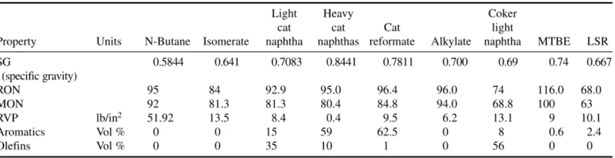
Gasoline Engine / 29 Gasoline Properties / 29 Gasoline Blend Components / 32 Pollution from Gasoline Combustion / 37 Catalytic Converter / 38
Gasoline Specifications / 39 Aviation Gasoline / 41 Racing Fuels / 46 References / 47
Chapter 4. Kerosene 49
Jet Engine / 49
Chapter 5. Diesel Fuels 65
Diesel Engines / 65 Specifications / 65 Diesel Fuel Emissions / 71 Diesel Fuel Additives / 74 Diesel Blending / 75 Distillate Heating Oils / 76 Biodiesels / 77
References / 80
Chapter 6. Residual Fuel Oils 81
Uses of Residual Fuels / 81 Diesel Engines / 82 Steam Boilers / 82 Gas Turbines / 82
Residual Fuel Oil Specifications / 82 Properties of Residual Fuel Oils / 85 Residual Fuel Oil Burning / 92 Residual Fuel Oil Blending / 94 Compatibility of Residual Fuel Oils / 96 References / 98
Part 2 Petroleum Specialty Products
Chapter 7. Bitumen 101
Bitumen Composition / 102 Bitumen for Pavement / 103 Bitumen Evaluation for Paving / 105 Bitumen Grading Systems / 113 Hot-Mix Asphalt / 117 Bitumen Test Methods / 118 Types of Bitumen / 122 Air Blowing Process / 131 Industrial Uses of Bitumen / 134 Storage and Handling of Bitumen / 137 References / 139
Chapter 8. Petroleum Coke 141
Manufacturing Processes / 141 Delayed Coking Process / 141 Operating Conditions / 145 Fluid Coking Process / 150 Petroleum Coke Types / 154 Properties of Calcined Coke / 156 Uses of Petroleum Coke / 158 Aluminum Smelting / 160 Titanium Dioxide Production / 161 Steel Production / 162
Graphite Electrodes / 162 References / 163
Chapter 9. Carbon Black 165
Manufacturing Processes / 166 Channel Black Process / 166 Gas Black Process / 167 Thermal Black Process / 167 Acetylene Black Process / 167 Lamp Black Process / 168 Furnace Black Process / 168 Reactor / 169
Oxidized Carbon Blacks / 173 Carbon Black Properties / 174 Secondary Properties / 176 Carbon Black Test Methods / 177 Application and Uses / 179 Printing Inks / 185 Cosmetics Usage / 187 References / 188
Chapter 10. Lube Base Stocks 189
Conventional Process / 189 Catalytic Dewaxing / 206
American Petroleum Institute Classification of Base Oils / 209 References / 210
Chapter 11. Lubricating Oil Blending 211
Classification of Lubricating Oils / 211 Classification by Viscosity / 212 International Standards / 212 Classification by Additive Types / 212 Automotive Engine Oils / 212
Effect of Viscosity on Fuel Economy / 216 Automotive Oil Additives / 216
Viscosity Index Improvers / 217 Detergent Inhibitors / 219 Dispersants / 220
Anti-Wear/Extreme Pressure Additives / 221 Friction Modifiers / 222
Oxidation Inhibitors / 222 Rust and Corrosion Inhibitors / 223 Pour Point Depressants / 223 Antifoamant Additives / 223 Other Additives / 223 Additive Depletion / 224 Engine Oil Formulation / 225 Effect of Base Stock Quality / 228
American Petroleum Institute Service Classification / 229 Gear Oils / 229
SAE Gear Oil Classification / 230 Automotive Lubricants Test Methods / 231 Cold Crank Simulator (ASTM D 5293) / 233 Four-Ball Wear Test (ASTM D 4172) / 234 References / 234
Chapter 12. Synthetic Lubricants 235
Polyalphaolefins / 236 Diesters / 236 Polyol Esters / 237 Polyalkylene Glycols / 238 Phosphate Esters / 239 Natural Esters / 240 Polyphenyl Ethers / 240 Fluorinated Lubricants / 241 Silicate Esters / 241 References / 242
Chapter 13. Turbine Oils 243
Base Oils / 243 Formulation / 244 Life of Turbine Oil / 245 Test Methods / 245 References / 247
Chapter 14. Used Oil Re-Refining 249
Burning as Fuel / 249 Re-Refining / 251 Re-Refining Processes / 251 Batch Acid-Clay Process / 251 Pretreatment / 255
Hydrofinishing Process / 255 References / 256
Chapter 15. Lubricating Greases 257
Grease Composition / 257 Base Oil / 258
Grease Thickeners / 258 Additives / 260
Grease Manufacture / 261 Lubricating Grease Quality / 263 Automotive Greases / 268 Aircraft Greases / 269 Heavy Machinery Greases / 269 Marine Greases / 272
High-Temperature Greases / 273 References / 275
Chapter 16. Waxes 277
Nonpetroleum Waxes / 277 Paraffin Waxes / 280 Properties / 281 Test Methods / 283
Petroleum Wax Manufacture / 285 References / 294
CONTENTS xiii
Chapter 17. Metalworking Fluids 295
Types of MWFs / 295 Functions of MWFs / 298
Blend Components of Cutting Oils / 299 Cutting Fluid Formulation / 301
Cutting Fluid Maintenance and Disposal / 301 References / 303
Chapter 18. Metal Finishing Quenchants 305
Heat Treating Processes / 305 Quenching/Hardening / 305 Types of Quenchants / 306 Three Stages of Heat Removal / 307 Accelerated Quenching / 308 Marquenching / 308 Mineral Quenching Oils / 308 Polymer Solutions / 310 Quench System Design / 310 Other Heat Treating Processes / 312 References / 312
Chapter 19. Hydraulic Fluids 313
Physical Properties / 314 Biodegradability / 316
Base Oils for Hydraulic Fluids / 316 Brake Fluids / 319
References / 320
Chapter 20. Petroleum Products as Pesticides 321
Spray Oils / 321
Chemical Insecticides / 325 References / 340
Chapter 21. Hydrocarbon Solvents 341
Nonpetroleum Solvents / 341 Petroleum-Based Solvents / 341
Major Applications of Petroleum Solvents / 344 References / 355
Chapter 22. Refrigeration Gases 357
Freons / 357
Refrigerants’ Name and Numbering Convention / 357 Aerosols / 361
xiv CONTENTS
Chapter 23. Transformer/Electrical Insulating Oils 365
Properties/Specifications / 365 Transformer Oils Manufacture / 370 References / 375
Chapter 24. White Mineral Oils 377
Properties of White Oils / 377 Uses of White Mineral Oils / 380 White Oil Manufacture / 381 Process Description / 382 Intermediate Product Storage / 382 Intermediate Product Nomenclature / 382 Sulfonate Blending / 385
Percolation / 387 Bauxite Processing / 388 New Bauxite Reactivation / 388 Naphtha Recovery / 389 Hydrotreating Process / 390 Hydroprocessed Base Stocks / 391 Petroleum Sulfonates / 391 Petrolatums / 392 References / 428
Appendix 429
xv
PREFACE
Petroleum products are everywhere around us. They appear in visible forms, such as gasoline, diesel, kerosene, and aircraft fuels, and in less visible forms over the entire spectrum of industry, such as automobile lubricants, greases, carbon black for truck tires, bitumen for road building, the water-proofing in house roofs, feedstock for petrochemicals, synthetic fibers, and plastics. Petroleum feed-stock is used in the manufacture of white mineral oils in eye ointment, hair oils, cosmetics, petroleum solvents, and pest control sprays. Transportation fuels, however, remain the most impor-tant use of petroleum.
The consumption of petroleum products throughout the world is ever-increasing to meet the rising energy needs of countries. But this rapid rise has led to undesirable air and water pollution levels. Environmental pollution affects everyone on the planet. During the last two decades, the manufacture and blending of petroleum products has changed rapidly, with a view to reduce atmos-pheric pollution and conserve petroleum feedstock. The lead phaseout from gasoline, sulfur reduction in all transportation fuels, and new lube-making technologies that produce longer-lasting engine oils or lower fuel consumption are a few illustrations of these changes.
This book surveys the manufacture, blending, properties, specifications, and uses of petroleum fuels and specialty products (products made out of petroleum feedstock for nonfuel use except petro-chemicals). There are a very large number of specialty products—petroleum solvents, bitumen for paving and industrial uses, lubricating oils, greases, white mineral oils, carbon black, petroleum coke, spray oils, and so on—to meet the requirements of industry. Possibly far more technical per-sonnel are engaged in petroleum specialty manufacture and the handling of petroleum products than are found in refineries. Although petroleum fuels are generally made in refineries out of crude oil distillation, petroleum specialty products are made in relatively smaller downstream units starting with refinery streams as feedstock. A refinery may produce five or six basic products, such as liqui-fied petroleum gas (LPG), naphtha, kerosene, diesel, and fuel oils, but specialty manufacturers may produce a large number of their products from these basic refinery products. There is very little pub-lished information on specialty manufacturing processes. The selection of a petroleum product for a specific job has become more challenging. Specifications and the test methods used on petroleum products are important for the proper selection of a petroleum product for a given end use.
Part 1, the first six chapters, is devoted to petroleum fuels. Part 2, the remaining chapters, deals with petroleum specialty products. The book presents manufacturing processes, product blending, and specifications of various petroleum products. To make the book useful to the professional in the petroleum industry, an in-depth treatment of each subject not normally found in textbooks is pro-vided. It is hoped that this book will be of direct interest to students and all those engaged in the man-ufacture, blending, storage, and trading of petroleum products.
PETROLEUM FUELS
MANUFACTURING
PETROLEUM FUELS
CHAPTER 1
LIQUEFIED PETROLEUM GAS
3
Liquefied petroleum gas, commonly called LPG, is also known by the names of its principal generic components, propane and butane. The normal constituents of LPG are propane (C3H8), propylene (C3H6), butane (C4H10), and butylenes (C4H8). These are commercial products and may contain other impurities such as smaller quantities of C5+ hydrocarbons. LPG as a liquid is colorless, and in vapor form it cannot be seen. Pure LPG has no smell, but for safety reasons an odoring agent, usually a mercaptan, is added during manufacture to aid detection at very low concentrations. LPG exists in a gaseous form under normal atmospheric pressure and temperature. It is easily liquefied by moderate pressure at ambient temperatures, which means it can be easily and conveniently stored as a liquid, a big advantage over natural gas, which can be liquefied only at a very low temperature and high pressure. LPG as a liquid is 250 times denser than LPG as vapor, so a large quantity can be stored in a relatively small volume.
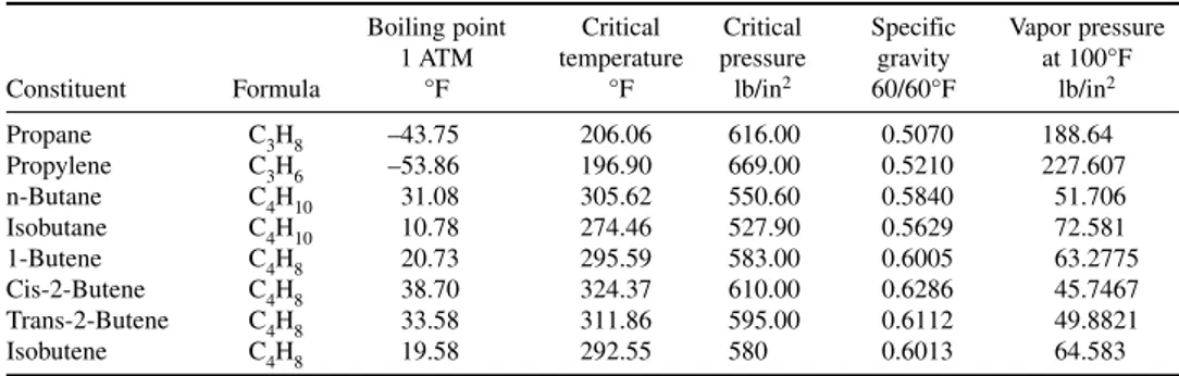
Table 1-1 shows the physical properties of LPG constituents. The boiling point at atmospheric pressure of n-butane is 31.08°F and for propane is –43.7°F. Thus propane can be stored in liquid form in tanks exposed to the atmosphere without the danger of freezing in cold winter ambient tempera-tures. The calorific value of LPG on a volume basis is significantly higher (propane, 95 MJ/m3; butane, 121 MJ/m3) compared with that of natural gas (38 MJ/m3). For this reason, natural gas appli-ances and LPG appliappli-ances cannot be interchanged.
LPG has the following main uses:
1. LPG is the most versatile fuel used in domestic applications. It is used like natural gas and can do everything that natural gas can do. LPG is used for cooking, central heating, space heating, and hot water supply, as well as in a large number of appliances, such as ovens, stovetops, and refrigerators in homes, hotels, and restaurants.
2. LPG is increasingly being used as automobile fuel because of its cost advantage over gasoline and diesel. LPG is a clean-burning fuel. The absence of sulfur and very low levels of nitrogen oxides (NOx) and particulate emissions during its combustion make LPG a most environmentally friend-ly source of energy. The disadvantage is that LPG has a lower calorific value per unit volume, and thus the vehicle has to refuel more frequently. In industry, LPG is used to power industrial ovens, kilns, furnaces, and for various process heating applications. LPG is used in brick kilns and aluminum die casting, in ceramics, and in glass manufacture. LPG is used to heat bitumen for road building. It has other diverse uses, such as the following:
• In agriculture, for crop drying, waste incarnation, greenhouse heating, and running power equipment.
• As a feedstock for chemical manufacture, in water desalination plants, and in aerosol manufac-ture as a propellant.
• As a standby fuel for natural gas. LPG is used as automobile fuel in forklift trucks.
AUTOMOTIVE LPG
Automotive LPG, or autogas, refers to the LPG used in automotive applications. LPG consists mainly of propane, propylene, butane, and butylenes in various proportions. The composition of autogas varies from country to country depending on the prevailing ambient temperatures. In moderate ambient temperatures, autogas typically consists of 60 to 70 percent propane and 30 to 40 percent butane. The addition of butane slows down combustion speed in an engine and reduces NOx emissions. Components of LPG are gases at normal ambient temperature and pressure but can be easily lique-fied for storage by an increase in pressure from 8 to 10 bar or a reduction in temperature. LPG used in automobiles is stored in liquid form in an onboard steel cylinder. LPG has a long and varied history in transportation applications. It is estimated that more than 4 million automobiles use LPG world-wide at present. It has been used in rural farming areas as fuel for farm machinery. LPG is used for some special applications such as forklifts in warehouses. The use of LPG can result in lower vehicle maintenance costs, lower emissions, and fuel cost savings compared with conventional gasoline or diesel fuels. LPG is considered a particularly suitable fuel for heavy vehicles, buses, and delivery vehicles because of its significantly lower particulate emissions compared with diesel-powered buses. The use of LPG as automotive fuel varies from country to country depending on the relative cost of alternative fuels such as gasoline and diesel.
LPG STORAGE
For domestic applications, LPG is stored in 15-kg cylinders. Domestic bulk LPG tanks vary in size from 200 to 2000 kg. They are installed outdoors on customer premises and LPG is delivered from road tankers. The amount of gas delivered is recorded via an onboard meter and charged to the customer. Storage tanks are usually installed aboveground. Propane is stored in a tank as a liquid under a pressure of 7 to 10 bars (100 to 150 PSIA). The gas pressure is reduced in two stages to bring it to a safe working pressure of 37 millibar (0.53 lb/in2), for which the gas appliances are usually designed to operate.
LPG MANUFACTURE
LPG from Field Gases
About 60 percent of the world supply of LPG comes from associated gas processing, and 40 percent of the LPG is produced in oil refineries from crude distillation, fluid catalytic cracking units (FCCUs), delayed cokers, hydrocrackers, and other conversion processes. The worldwide estimated production of LPG in 2005 was estimated at 250 million tons per year.
4 PETROLEUM FUELS
TABLE 1-1 Properties of LPG Gases
Boiling point Critical Critical Specific Vapor pressure 1 ATM temperature pressure gravity at 100°F
Constituent Formula °F °F lb/in2 60/60°F lb/in2
Propane C3H8 –43.75 206.06 616.00 0.5070 188.64
Propylene C3H6 –53.86 196.90 669.00 0.5210 227.607
n-Butane C4H10 31.08 305.62 550.60 0.5840 51.706
Isobutane C4H10 10.78 274.46 527.90 0.5629 72.581
1-Butene C4H8 20.73 295.59 583.00 0.6005 63.2775
Cis-2-Butene C4H8 38.70 324.37 610.00 0.6286 45.7467
Trans-2-Butene C4H8 33.58 311.86 595.00 0.6112 49.8821
Acid Gas Removal
The raw natural or associated gases from a group of wells are received in a knockout drum where gas and liquid phases are separated. The gas is disentrained with the aid of a mist eliminator pad incorporated in the knockout drum and then compressed by a gas compressor for pipeline trans-port to an acid gas removal plant. Condensate separated in a knockout drum is injected back into the gas stream after water separation. Water separated in the knockout drum is disposed of as wastewater.
The oil field gases contain carbon dioxide and hydrogen sulfide, together known as acid gases. Because these gases are corrosive, poisonous, or both, they are removed first before further process-ing or LPG separation. Acid gases are separated from the gas stream by amine treatprocess-ing or by the Benfield process in which gases are treated with a solution of potassium carbonate containing some additives. The Benfield process uses an inorganic solution containing 25 to 35 wt % (percentage of weight) K2CO3. The absorption is chemical not physical. Figure 1-1 shows the reactions.
The Benfield solution has vanadium pentoxide (V2O5), which results in higher gas loading, lower circulation rate, and less corrosion. The absorber operates at 200 to 400°F.
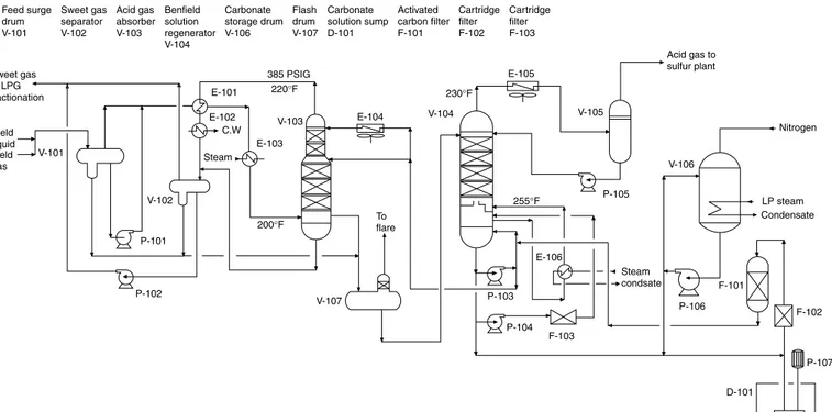
Figure 1-2 shows a process flow diagram of acid gas (CO2and H2S) removal based on the Benfield process. The gases and liquid coming from the field enter feed surge drum V-101, which removes any entrained water. The gas and liquid feed are recombined, and the two-phase mixture is heated in E-101 by heat exchange with sweet gas coming from the top of acid gas absorber V-103. It is further heated with 50 lb/in2steam in E-103. It is next fed to absorber V-103 near the bottom. A lean potassium car-bonate solution is fed to the absorber at its top and middle sections. The rich solution reaching the bot-tom of absorber is pumped to regenerator column V-104 via flash drum V-107. The sweet gas from absorber V-103 overhead is cooled in heat exchanger E-101 and next by cooling water in E-102 on its way to separator drum V-102 where the condensate is separated. Sweet gas exits the separator drum V-102 for further processing in an LPG extraction unit. Water separated in the drum is returned to flash drum V-107. Sweet hydrocarbon product is pumped out to mix with sweet gas from drum V-102. Potassium carbonate solution rich in acid gas is regenerated in V-104. The solution is fed to the top of a packed column. The rich solution is regenerated by reboiling with steam in reboiler E-106. The lean solution is collected at the bottom of the column and returned to the absorber. Any makeup potas-sium carbonate solution required by the absorber is drawn from carbonate storage drum V-106. The regenerator overheads are condensed by air cooler E-105 and collected in regenerator accumulator V-105. Acid gases remain uncondensed and exit V-105 to the sulfur plant.
Extraction Plant
The combined feed to extraction plant typically comprises associated gases and condensate from oil-producing areas plus refinery gases after treating for acid gas removal. The extraction process involves feed compression, feed/effluent heat exchange, dehydration, absorption, and stripping. Three product streams are produced; a liquid stream rich in propane, butane, and gasoline that is sent to the fractionation plant and two overhead gas streams that supply gas to the fuel system. Absorption oil is provided by a recycled gasoline product. A closed cycle propane refrigeration system supplies low-temperature chilling.
Referring to the process flow diagram in Fig. 1-3, oil field gases and refinery gases from acid gas removal plant are received in knockout drum V-201 at 336 lb/in2where gas and liquid phases are separated. The gas is compressed by gas compressor K-201 to 571 lb/in2and after-cooled in after-cooler E-201 while liquid separated is pumped by pump P-201 to accumulator drum V-202.
LIQUEFIED PETROLEUM GAS 5
K2 CO3 + CO2 + H2O = 2 KHCO3
K2 CO3 + H2S = KHS + KHCO3
6
Product gas
FIGURE 1-3 LPG extraction plant.
8 PETROLEUM FUELS
The mixed-phase feed from V-202 exchanges heat with stripper (V-204) bottoms in feed/stripper bottom exchanger E-202 and then reboils the stripper reboiler E-203. The feed gas is further cooled by chilling with high-level refrigerant propane in E-204. The condensed hydrocarbons are separat-ed from gas in V-203. Gases that leave V-203 go to gas dehydration unit U-201 while liquid hydro-carbons are pumped out by P-203 to a liquid dehydration unit.
Dehydration units are provided to remove moisture from gas and liquid and thus prevent freez-ing in the cold end of the plant. The gas enters the gas dehydration unit at 544 lb/in2and 72°F. When it leaves the unit, the water content is reduced to 1 ppm maximum. Similarly, water content of liquid phase is reduced to 4.5 ppm maximum.
The dried gas and liquid streams from dehydration unit U-201 are combined for further chilling in exchangers E-205 and E-206 and cooled from 72 to –20°F at the absorber column V-204 inlet. The absorber column V-204 recovers propane, butane, and heavier hydrocarbons, from the feed with a minimum loss of these components. The absorbent for this operation is natural gasoline recycled from fractionation plant debutanizer column bottoms. The two-phase feed at –20°F and 510 lb/in2enters the bottom of absorber V-204 where liquid and vapor are separated. The ascending vapor contacts the descending liquid absorbent on valve trays, and absorption of heavier components take place. The overhead vapor is mixed with chilled lean oil and cooled to –35°F by heat exchange with low-level propane in absorber oil presaturator E-207. The effluent from E-207 is phase separated in absorber reflux drum V-206. The liquid from reflux drum is pumped by reflux pump P-204 to absorber column as reflux. Absorber overhead vapor leaves the plant to product gas/fuel systems. The rich liquid from absorber bottom is transferred to a stripper V-205 via a throttle valve. The function of stripping column V-205 is to reduce the methane and ethane content of the absorber bottoms. Stripping is done at reduced pressure, approximately 260 lb/in2. The absorber bottoms are let down to stripper bottom pressure and flashed into the stripper column. Most of the methane and some ethane are flashed off and ascend to the top of the column contacting the descending reflux on valve trays where some of the heavier components are reabsorbed. The stripper overheads are mixed with chilled lean oil and cooled to –35°F by low-level propane in stripper oil presaturator E-208. The cold mixture is separat-ed in stripper reflux drum V-207, and the liquid is pumpseparat-ed by reflux pump P-205 to the stripper col-umn. The overhead vapor from V-206 leaves the plant to a gas distribution/fuel system.
Fractionation Plant
The stripper bottom product from the LPG extraction plant is comprised of propane, butane, and natural gasoline with some associated ethane and lighter components. This stripper bottom consti-tutes feed to the LPG fractionation plant where it is separated into a gas product, propane, butane, and natural gasoline in three fractionation columns.
Deethanizer. Referring to the process flow diagram in Fig. 1-4, the stripper bottoms from the extraction plant enter deethanizer column V-101 near the top. The overhead vapor is partially con-densed in deethanizer condenser E-101 by heat exchange with medium-level propane at 20°F. Condensed overhead product in overhead reflux drum V-104 is pumped back to the deethanizer by reflux pump P-101. The noncondensed vapor, mainly ethane, leaves the plant to fuel the gas system. Heat is supplied to the column by forced circulation reboiler E-104. The deethanizer column oper-ates at approximately 390 lb/in2. Approximately 98 percent of the propane in the deethanizer feed is recovered in the bottom product. The residual ethane concentration is reduced to approximately 0.8 mol % (mole percentage) in the bottom product. The bottom product from deethanizer pressure drains into depropanizer column V-102.
Column V-102 reboil heat is supplied by direct-fired heater H-101. Reboiler circulation is aided by reboiler circulation pump P-104. The bottom product is sent to debutanizer column V-103.
Debutanizer. The depropanizer bottoms are expanded from approximately 290 to 110 lb/in2and enter the debutanizer column as a mixed-phase feed. The column feed is fractionated into a butane-rich overhead product and natural gasoline bottoms. The columns overhead are totally condensed in the debutanizer condenser E-103 by heat exchange with cooling water, and condensate is collected in reflux drum V-106. The debutanizer reflux and product pump P-105 serve the dual purpose of sup-plying reflux to the column and allowing withdrawal of column overhead product butane from the reflux drum. The column reboil heat is supplied by a direct-fired debutanizer reboiler H-102, and the boiler circulation is aided by debutanizer reboiler circulating pump P-106. The bottom product leav-ing the column is cooled in product cooler E-105. A part of the gasoline product is recycled to the LPG extraction unit and serves as lean oil for the absorber column.
Product Treatment Plant
Propane and butane products from the fractionation plant contain impurities in the form of sulfur compounds and residual water that must be removed to meet product specifications. The impurities are removed by adsorption on molecular sieves. Each product is treated in a twin fixed-bed molecular sieve unit. Regeneration is done by sour gas from the stripper overhead followed by vaporized LPG product. Operating conditions are listed in Table 1-2 and impurities to be removed are listed in Table 1-3.
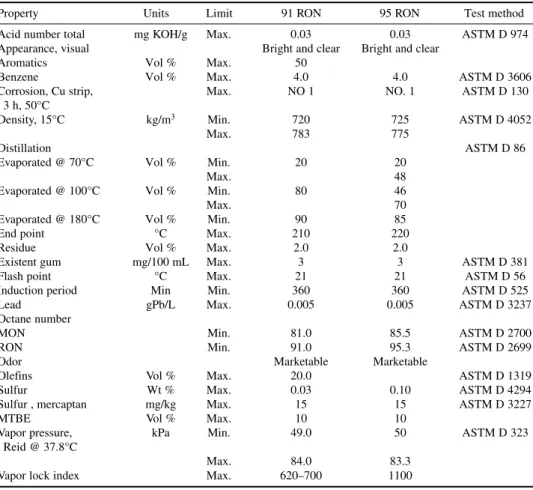
LPG SPECIFICATIONS
Commercial propane and butane specification conforming to U.S. Gas Processor Association stan-dards are listed in Tables 1-4 and 1-5. Indexes for “R” and “O” give residue and oil stain results, respectively, in whole numbers. In these specifications, under residual matter, “R” refers to residue volume in milliliters multiplied by 200. “O” refers to 10 divided by oil stain observation in millimeters. Specifications for autogas conforming to EN 589 are listed in Table 1-6. The most important speci-fications for auto LPG are motor octane number and vapor pressure. Commercial butane-propane (BP) mixtures used for domestic uses contain varying amounts of C3and C4hydrocarbons as per the ambient conditions (Table 1-7).
10 PETROLEUM FUELS
TABLE 1-2 Molecular Sieve Product Treating Process Operating Conditions
Operating variable Units Propane Butane
Pressure lb/in2 325 155
Temperature °F 110 110
Phase Liquid Liquid
TABLE 1-3 Typical Contaminant Level in Untreated LPG
Contaminants Units Propane Butane
H20 wt ppm 10 Trace
H2S wt ppm 100 Trace
COS wt ppm 34 Trace
C3SH wt ppm 100 40
C2H5SH wt ppm Trace 220
TABLE 1-4 Commercial Propane Specifications
Property Units Limit Value Test method
Composition ASTM D 2163
C2and lighter Mol % Max. 2.0
C3hydrocarbons Mol % Min. 96.0
C4and heavier Mol % Max. 2.5
Cu corrosion strip, 1 h @ 37.8°C Max. No. 1 ASTM D 1838
Hydrogen sulfide Negative ASTM D 2420
Moisture content Pass ASTM D 2713
Residual matter ASTM D 2158
“R” number Max. 10
“O” number Max. 33
Relative density 60/60°F Report ASTM D 1657/D 2598
Sulfur ppm Max. 60 ASTM D 2784/D 3246
Vapor pressure @ 37.8°F lb/in2 Max. 200 ASTM D 1267
Ammonia ppm Max. Report Drager tubes
Carbonyl sulfide ppm Max. Report UOP 212
Diene Mol % Max. 0 ASTM D 2163
Hydrogen sulfide (H2S) ppm Report UOP 212
Unsaturates Mol % Max. 1.0 ASTM D 2163
Volatile residue
LIQUEFIED PETROLEUM GAS 11
TABLE 1-5 Commercial Butane Specifications
Property Units Limit Value Test method
Composition ASTM D 2163
C4Hydrocarbons Mol % Min. 95.0
C5and heavier Mol % Max. 2.0
Free water content Visual None
Cu corrosion strip, 1 h @ 37.8°C Max. No. 1 ASTM D 1838
Hydrogen sulfide Negative ASTM D 2420
Relative density 60/60°F Report ASTM D 1657/D 2598
Sulfur ppm Max. 60 ASTM D 2784/D 3246
Vapor pressure @ 37.8°F lb/in2 Max. 70 ASTM D 1267
Ammonia ppm Max. Report Drager tubes
Diene Mol % Max. 0 ASTM D 2163
Hydrogen sulfide (H2S) ppm Max. Report UOP 212
Unsaturates Mol % Max. 1.0 ASTM D 2163
Volatile residue
Temperature @ 95% evaporation °C Max. 2.2
TABLE 1-6 Autogas (LPG for Automobiles) Specifications
Characteristics Units Limit Value Test method
Vapor pressure, 40°C kPa Min. 800 ISO 8973
Max. 1530
Volatile residue (C5 and heavier) Mol % Max. 2.0 ISO 7941
Diene Mol % Max. 0.5 ISO 7941
Total volatile sulfur mg/kg Max. 100 ASTM D 2784
Motor octane (Mon) Min. 90.5 ISO 7941/EN 589
Cu strip corrosion test, 38°C No. 1 EN ISO 6251
Residue on evaporation mg/kg Max. 100 JLPGA-S-03
Moisture content, @ 0°C NIL EN 589
Hydrogen sulfide NIL EN ISO 8819
TABLE 1-7 Commercial LPG (B-P Mixture)
Property Units Limit Value Test method
Composition ASTM D 2163
C3Hydrocarbons Mol % Min. 22.0
Max. 24.0
C4Hydrocarbons Mol % Min. 76.0
Max. 78.0
Cu corrosion strip, 1 h @ 37.8°C Max. No. 1 ASTM D 1838
Hydrogen sulfide Negative ASTM D 2420
Odorant
Tetrahydrothiophene *
Relative density 60/60°F Report ASTM D 1657/D 2598
Residual matter ASTM D 2158
“R” number Max. 10
“O” number Max. 33
Sulfur ppm Max. 60 ASTM D 2784/D 3246
Vapor pressure @ 37.8°C lb/in2 Max. 93 ASTM D 1267
CHAPTER 2
NAPHTHA
Naphtha is the lightest liquid distillate product of crude distillation consisting of C5 to C10 hydrocarbons boiling in the 100 to 310°F range. It is produced from the atmospheric distil-lation of crude oil and from many secondary processing units in the refinery. Unlike other petro-leum fuels such as kerosene, diesel, or fuel oil, naphtha is not a direct petropetro-leum fuel but is used as a feedstock for the manufacture of plastics and polymers, synthetic fiber, petrochemicals, fertilizer, insecticides and pesticides, industrial solvents for making specialty solvents such as food grade hexane, dyes, and chemicals. In refineries, naphtha is one of the basic feedstocks for the manufacture of gasoline. At locations where natural gas is not available, naphtha is used as a feedstock for producing hydrogen required for hydroprocessing units in refineries. Naphtha is sometimes used as fuel in gas turbines or boilers for power generation units. The worldwide naphtha demand in 2006 was estimated at 900 million tons.
NAPHTHA PRODUCTION
Naphtha is produced from the following units:
• Crude distillation units in the refinery. • Secondary processing units in the refinery.
• Gas-processing units separating LPG from field gases. Naphtha thus separated is known as natural gas liquid.
Crude Distillation Unit
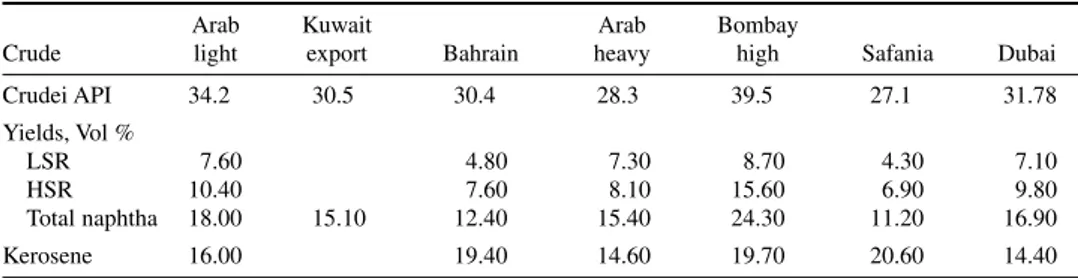
The yield of naphtha cut from crude distillation depends on the crude oil processed. Lighter crude oils yield larger volumes of naphtha on processing. Table 2-1 lists the yield of naphtha from some Middle Eastern crude oils. Naphtha produced in the refinery is typically a straight C5-310°F cut from the crude distillation unit. Naphtha cut withdrawn from crude column is not a sharp cut because it contains lighter as well as heavier components such as LPG and kerosene.
Naphtha production in the refinery is a two-step process:
1. Production of a broad cut from a crude distillation unit (CDU).
2. Refractionation of the broad naphtha cut to remove light and heavier components.
In the CDU (Fig. 2-1), crude oil is preheated by heat exchange with product streams and enters preflash tower V-100. The preflash tower is a small distillation column with four to five plates that removes most of the LPG gases and some light naphtha as overhead product. The preflash tower top vapors are cooled in exchangers E-101 and E-102 and collected in reflux drum V-103. A part of this preflashed naphtha is sent back to column V-100 as reflux, and the rest is routed to naphtha refrac-tionation section via V-102. The topped crude from the preflash tower is fed to main atmospheric
distillation column V-101. Naphtha is withdrawn from the crude distillation column’s reflux drum V-102 and routed to the naphtha refractionation unit. Naphtha liquid withdrawn from the CDU column reflux drum V-102 contains heavy ends that must be removed. Similarly, the LPG gas prod-uct from V-102 reflux drum contains some naphtha vapor that must be recovered. Naphtha vapors from V-102 are compressed in compressor C-101 and cooled in a series of water-cooled heat exchangers.
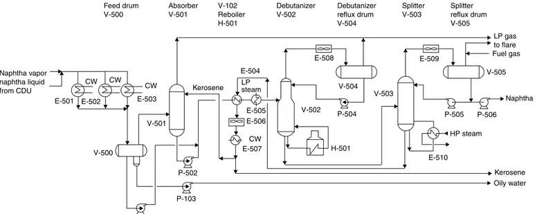
Naphtha Refractionation Unit. The condensed naphtha is collected in naphtha feed drum V-500 (Fig. 2-2). The uncondensed vapors from V-500 enter absorber V-501 near the bottom and are absorbed in a stream of kerosene that enters V-501 near the top. The rich kerosene stream
14 PETROLEUM FUELS
FIGURE 2-1 Simplified process flow diagram for naphtha production from crude distillation unit in refinery.
Crude TABLE 2-1 Yield of Naphtha from Various Crude Oils
Arab Kuwait Arab Bombay
Crude light export Bahrain heavy high Safania Dubai
Crudei API 34.2 30.5 30.4 28.3 39.5 27.1 31.78
Yields, Vol %
LSR 7.60 4.80 7.30 8.70 4.30 7.10
HSR 10.40 7.60 8.10 15.60 6.90 9.80
Total naphtha 18.00 15.10 12.40 15.40 24.30 11.20 16.90
15
Naphtha vapor naphtha liquid from CDU
Absorber V-501
Debutanizer V-502
Splitter V-503 Feed drum
V-500
V-500 CW
CW CW
Kerosene
Debutanizer reflux drum V-504
V-504
Splitter reflux drum V-505
HP steam V-102
Reboiler H-501
H-501
LP gas to flare Fuel gas
Kerosene Oily water E-501 E-502 E-503
E-504
E-505 E-506
CW E-507
E-508 E-509
E-510
P-101
P-502
P-103
P-504 P-505 P-506
Naphtha LP
steam
V-502
V-503
V-505
V-501
16 PETROLEUM FUELS
leaving V-501, along with condensed naphtha from V-500 after heating with steam in E-505, enters debutanizer column V-502, which removes all C4 and lighter product from naphtha as overhead product. The bottom product from debutanizer V-502 is sent to a splitter column V-503 where naph-tha is removed as a top product and kerosene as a bottom product. A part of kerosene is recycled to absorber V-501 as sponge oil.
Production from Secondary Processing Units
Naphtha is also produced from secondary conversion units such as distillate hydrocrackers, delayed coker units, and resid hydrocrackers. Small quantities of naphtha are also produced by distillate desulfurizer units. However, the distillate hydrocracker is the most important conversion unit, which produces approximately 31 vol % (percentage of volume) naphtha on feed. Compared with straight run naphtha, hydrocracker naphtha has a lower paraffin and higher naphthene content. Hydrocracker heavy naphtha, because of its high naphthene content, is a preferred feedstock for catalytic reformer units. Feed with high naphthene content gives a higher reformate and hydrogen yield.
Production from Associated Gas
Almost 10 percent of total naphtha production comes from associated gas processing. A large quantity of associated gas is also produced as a by-product during crude oil production. Gas separated from oil may contain carbon dioxide, hydrogen sulfide, methane, ethane, propane, normal butane and isobutane, and C5+ hydrocarbons. The typical associated gas composition from a Middle Eastern oil field is listed in Table 2-2. The gas is first processed to remove acid gases (CO2and H2S). Next C3+ components such as propane, butane, and natural gasoline are separated from C1 and C2 gases by cooling with a propane refrigeration system to a low temper-ature. C3+ hydrocarbons condense as liquid and are separated in a flash drum. The separated hydrocarbons are further separated into propane, butane, and natural gasoline by fractionation in a series of columns. The separated C1 and C2 gases are stripped of any heavier hydrocarbons
TABLE 2-2 Typical Associated Gas Composition
Component Weight %
H2 0.00
N2 0.22
CO2 2.61
H2S 0.04
C1 37.40
C2 20.97
C3 19.42
I C4 3.31
N C4 8.16
I-C5 2.00
N C5 2.63
C6 2.44
C7 0.51
C8 0.20
C9 0.05
C10+ 0.01
Water 0.03
NAPHTHA 17
they may contain by absorbing in natural gasoline liquid in an absorber. Naphtha produced from associated gas is called light naphtha. Table 2-3 lists its composition and properties. Light naphtha consisting mainly of C5 and C6 hydrocarbon components is a preferred isomerization unit feed. Isomerization unit isomerizes C5 and C6 normal paraffins to branched chain hydrocarbons and increases the research octane number (RON) from 70 to 83. Isomerate is an important gasoline blend component for controlling the Reid Vapor Pressure (RVP) and distillation specification of blended gasoline.
SECONDARY PROCESSING UNITS
Table 2-4 lists the typical naphtha yield from various secondary processing units. Naphtha prop-erties from secondary processing units such as the distillate hydrocracker and delayed coker are presented in Tables 2-5 and 2-6. Naphthas produced from coker or resid hydrocrackers usually have high nitrogen, sulfur, and olefin content, and they require hydrotreating before blending into the naphtha pool.
TABLE 2-3 C4+ Natural Gasoline Composition and Properties*
Vol %
Isobutane 0
Normal butane 0
Isopentane 25.6
Normal pentane 37.7
Cyclopentane 0
2,2 Dimethyl butane 1.2
2,3 Dimethyl butane 2.2
2 Methyl pentane 9.7
3 Methyl pentane 6.3
Normal hexane 2.2
Methyl cyclopentane 5.2
Cyclohexane 5.8
Benzene 1.8
C7+ 2.3
Density, g/mL 0.6568
PONA, vol %
Paraffins 73.9
Naphthene 15.1
Aromatics 11
Sulfur, ppmw 0.5
*Separated from field gases.
TABLE 2-4 Naphtha Yield from Various Refinery Units
Units Naphtha yield
Distillate hydrocracker Vol % 31.5
Delayed coker Vol % 1.9
Resid hydrocracker ( H oil) Vol % 7.3
Resid desulfurizer Vol % 3.0
Diesel desulfurizer Vol % 0.9
NAPHTHA DESULFURIZATION
Naphtha produced from crude oil distillation, coking units, or from field gases may contain sulfur, mercaptan, and H2S as impurities that must be removed or reduced to a low level before naphtha can be used as feedstock in any downstream catalytic process. The naphtha hydrodesulfurization (HDS) unit serves to make naphtha feed suitable for catalytic conversion processes by removing sulfur, nitrogen, trace metals, or other catalytic poisons from feed. This is done by reacting feed
18 PETROLEUM FUELS
TABLE 2-6 Light Coker Naphtha Properties
Property Units Value
Gravity °API 82.1
Density, 60/60°F kg/L 0.662
Distillation IBP
10 vol % °F 118
50 vol % °F 126
90 vol % °F 147
RON clear 81.8
PONA
Paraffins Vol % 36
Olefins Vol % 56
Naphthenes Vol % 0
Aromatica Vol % 8.0
Bromine number 70.0
Nitrogen content ppm 100.0
Sulfur Wt % 0.10
Reid vapor pressure kPa @100°F 91
TABLE 2-5 Light and Heavy Naphtha Properties Ex Hydrocracker
Property Units C5-180°F 180–320°F
Gravity °API 79 52.5
Density g/mL 0.672 0.769
Aniline point °F 107
Distillation °F
IBP 110 215
10% 115 225.0
30% 125 245.0
50% 135 260.0
70% 150 270
90% 170 295
EP 195 325
PONA Vol %
Paraffins 74 27
Naphthenes 22 58
Aromatics 4 15
Sulfur ppm <10 <10
NAPHTHA 19
with hydrogen at high temperature and pressures. Sulfur is converted to H2S and nitrogen to NH3, which are removed by distillation. Typical desulfurization reactions occurring in the HDS reactor are shown in Fig. 2-3.
Naphtha feed to cat reformers must meet 1 ppm or lower sulfur level specifications to protect noble metal catalyst in the reforming unit. In the naphtha steam reforming process for the produc-tion of hydrogen, naphtha sulfur must be reduced to less than 0.5 ppm in order to prevent poisoning of the nickel catalyst in the reactor. Sulfur is removed from naphtha in a naphtha desulfurization unit. However, if only H2S is present in the feed, vapor feed is passed over a guard reactor containing ZnO, which absorbs H2S.
NAPHTHA HDS UNIT
Referring to the process flow diagram in Fig. 2-4, naphtha feed from storage tanks is pumped by charge pump P-101 through reactor effluent-feed exchangers E-101 to E-103 and fired heater H-101 into the top of reactor V-101. The reactor is loaded with a desulfurization catalyst consist-ing of cobalt-molybdenum (Co-Mo) metals on an alumina base. Hydrogen from the catalytic reformer or hydrogen plant is compressed by centrifugal compressor C-101 and sent to the feed stream upstream of the reactor feed exchanger. The reactor effluent is cooled in effluent-feed exchangers E-101, E-102, E-103, in air cooler E-104, and in trim water cooler E-105 before flowing into high-pressure (HP) separator V-102. Hydrogen-rich vapors from a HP separator are routed back to compressor C-101. A small part of this stream is purged off to prevent buildup of H2S in the hydrogen stream. HP separator liquid is flashed in low-pressure separator V-103 where H2S and lighter hydrocarbons are separated from liquid. The liquid from V-103 is pumped to sta-bilizer column V-104 through feed/bottom exchanger E-106. Stasta-bilizer column V-104 overhead vapors are condensed in air cooler E-107 and in water trim cooler E-108 and flow into accumulator V-105. The vapor from the accumulator (C4 and lighter) along with gas from the flash drum is sent to an amine unit for H2S removal and gas recovery. The liquid from the V-105 is returned to the stabilizer column as total reflux. Stabilizer bottoms flow through E-106 to dehexanizer column V-106. The objective of dehexanizer column V-106 is to split desulfurized naphtha into light and heavy naphtha. Heavy naphtha is used as a feed for the catalytic reforming unit. The dehexanizer overhead vapors are condensed in E-109 and flow into reflux drum V-107. A part of the condensed liquid is sent back to the column as reflux, and the remainder is pumped through water trim cooler E-113 to storage as light naphtha (C5/C6) product. Dehexanizer bottoms (heavy naphtha) are cooled by pumping through air cooler E-111 and water trim cooler E-112 and routed to storage tanks. Table 2-7 lists the key operating conditions for a naphtha HDS unit.
Desulfurization
Denitrogenation
Hydrocarbon saturation CH = CH
C = CH R
R CH2 NH2 + H2
R CH2 CH2 + H2
S + 4 H2 R CH2 CH2 CH2 CH3 + H2S
R CH3 + NH3
R CH2 CH3
20
NAPHTHA 21
NAPHTHA SPECIFICATIONS
Naphtha may be classified by its boiling range or by its end use:
• Light straight run (LSR) naphtha • Wide straight run (WSR) naphtha • Petrochemical naphtha
LSR NAPHTHA
LSR naphtha is a light naphtha cut produced from crude oil distillation with a boiling range of C5 to180°F. It consists mainly of C5 and C6 hydrocarbons. It is highly paraffinic. The paraffin content of light naphtha is greater than 80 vol %. Table 2-8 lists the specifications of light naphtha, which is typically blended from hydrocracker light naphtha, meroxed coker light naphtha, and natural gasoline separated from associated gas. Specifications limit blending of light cracked naphtha such as light coker naphtha in LSR blends to an olefin content of 1.0 vol % maximum. LSR naphtha, because of its volatility, is a preferred feedstock for refinery isomerization unit to make a light gaso-line blending component. LSR naphtha has a low RON of approximately 60. In the isomerization unit, feed is vaporized, mixed with hydrogen, and passed over a platinum-impregnated chlorinated
TABLE 2-7 Naphtha HDS Unit Operating Conditions
Property Units Value
Reactor inlet temperature @ SOR/EOR °F 608/698
HP separator pressure kg/cm2 21.3
Hydrogen partial pressure kg/cm2 11.2
at reactor outlet
VVH (m3/h naphtha/m3catalyst) 15°C 4.00
TABLE 2-8 Light Naphtha Specifications
Property Units Limit Value Test method
Color, saybolt +20 ASTM D 156
Density kg/L Min. 0.645 ASTM D 1298
Max. 0.700
Distillation ASTM D 86
IBP Report
10 vol % °F Max. 131
50 vol % °F Max. 149
90 vol % °F Max. 239
End point °F Max. 320
Lead content ppb Max. 50 IP 224
PONA Chromatography
Paraffins Vol % Min. 80
Olefins Vol % Max. 1.0
Naphthene Vol % Max. 18.0
Aromatics Vol % Max. 5.0
Sulfur Wt % Max. 0.03 ASTM D 1266
alumina catalyst in an isomerization reactor. Isomerization of C5 and C6 normal paraffins to isoparaffins increases RON by 18 to 22 numbers. Isomerate is a very useful blend component to control gasoline distillation and to reduce high aromatic content reformate blending in gasoline.
WSR Naphtha
WSR is a (C5-310°F) cut from crude distillation units. Typical product specifications for WSR naphtha are listed in Table 2-9. A significant part of WSR is used as petrochemical naphtha or as a feedstock for the catalytic reforming unit for the production of a motor gasoline blend component.
22 PETROLEUM FUELS
TABLE 2-9 Wide Straight Run (WSR) Naphtha Specifications
Property Units Limit Value Test method
Color, Saybolt Report ASTM D 156
Density kg/L Min. 0.690 ASTM D 1298
Max. 0.735
Distillation ASTM D 86
IBP Report
10 vol % °F Min. 109
Max. 210
50 vol % °F Min. 174
Max. 270
90 vol % °F Min. 230
Max. 351
End point °F Max. 399
Lead content ppb Max. 200 IP 224
Olefins Vol % Max. 1.0 ASTM D 1319
or
Bromine number Max. 1.0 ASTM D 1159
PONA Report
Sulfur Wt % Max. 0.07 ASTM D 1266
Vapor pressure, Reid kPa @100°F Max. 75 ASTM D 323
Petrochemical Naphtha
In refineries, petrochemical naphtha is blended from the straight run naphtha ex-crude distillation column and hydrocracker naphtha. Naphtha used as petrochemical feedstock must be highly paraf-finic (minimum 70 vol %) with low aromatic content (less than 11 vol %). Table 2-10 lists the typical specifications of petrochemical naphtha.
NAPHTHA 23
NAPHTHA USES
Catalytic Reforming
Catalytic reforming is an important refinery process for the manufacture of gasoline from naphtha. Straight run naphtha from crude oil distillation consists mainly of paraffins and naphthenes. It has a low octane number and cannot be used for gasoline blending.
The catalytic reformer unit converts low-octane heavy naphtha to high-octane catalytic reformate. Reformate is used as a blend component for gasoline blending. The reformate octane number can be increased by increasing the process severity, that is, increasing the reactor temperature or decreasing the space velocity. Increasing severity decreases reformate yield. Most cat reformers for gasoline manufacture operate in the 95 to 100 RON severity range. The manufacture of aromatics requires cat-alytic reforming units with continuous catalyst regeneration, operating in a higher severity RON range (100 to 102).
Figure 2-5 presents the chemical reactions that take place during catalytic reforming. Important chemical reactions are dehydrogenation, dehydrocyclization, isomerization and hydrocracking. Dehydrogenation reactions convert naphthenes to aromatics with higher octane number. Dehydrocyclization reactions convert normal paraffins to naphthenes, and isomerization of normal paraffins convert n-paraffins to branched hydrocarbons with high RON. Hydrocracking of paraffins decreases molecular weight and increases the volatility of reformate. The yield of reformate is a function of feed paraffin, olefin, naphthene, and aromatic (PONA) and cat reformer operating con-ditions. Naphthas with high naphthene content are the preferred feed for the catalytic reformer unit. The cat reforming process also produces hydrogen gas, which can be used for various desulfuriza-tion units in the refinery.
Naphtha feed for the reformer unit comes from the naphtha desulfurization unit where naphtha, sulfur, and nitrogen are both reduced to below 0.5 ppm.
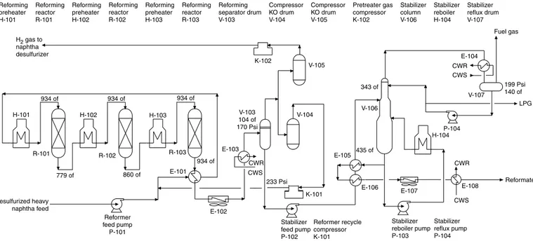
Referring to the process flow diagram in Fig. 2-6, in the reforming unit, naphtha feed from the naphtha HDS unit or storage tank is mixed with hydrogen from recycle compressor K-101
TABLE 2-10 Petrochemical Naphtha Specifications
Property Units Limit Value Test method
Color, Saybolt Min. +20 ASTM D 156
Density, 60/60°F kg/L Min. 0.680 ASTM D 1298
Max. 0.725
Distillation ASTM D 86
IBP Report
10 vol % °F Min. Report
Max.
50 vol % °F Min. 122
Max. 248
90 vol % °F Min. 167
Max. 320
End point °F Max. 356
Lead content ppb Max. 200 IP 224
Olefins Vol % Max. 1.0 ASTM D 1319
PONA
Paraffins Vol % Min. 70 Chromatography
Olefins Vol % Max. 1.0
Naphthene Vol % Report
Aromatics Vol % Report
Sulfur Wt % Max. 0.07 ASTM D 1266
and is preheated in feed-effluent exchanger E-101. The feed-hydrogen mix is next heated to reac-tion temperature by first fired heater H-101 and passed over reforming catalyst in first reactor R-101. Due to the endothermic nature of reactions, the temperature of the effluent coming out of the first reactor drops. It is reheated in the second fired heater H-102 after which the effluent from the first reactor enters the second reactor R-102. Effluent from the second reactor is reheated in third fired heater H-103 after which it enters the third reforming reactor R-103. Effluent from third reforming reactor is cooled first by heat exchange with incoming feed in E-101, next in air cooler E-102, and finally in trim water cooler to 104°F before entering HP separator drum V-103. Pressure in V-103 is controlled at 170 lb/in2. High-pressure gas, mainly hydrogen, is sent to recycle compressor K-101 and recirculated to incoming fresh feed. Reforming reactions produce large volumes of hydrogen. Excess hydrogen from a flash drum is sent to other refinery units via knockout (KO) drum V-105 and compressor K-102.
Liquid effluent from HP Separator V-103 is pumped via P-102 to stabilizer column V-106, which separates fuel gas and LPG as top product; reformate is the bottom product. Reformate is cooled by heat exchange with incoming feed in E-105, E-106, and next cooled in water cooler E-108 before sending it to storage.
24 PETROLEUM FUELS
CH3 CH3
+ 3H2
Methyl cyclohexane Toluene
CH3
Methyl cyclopentane Cyclohexane Benzene
Isomerization reactions
C6H14
C7H16
CH3 CH CH2 CH2 CH3 CH3
CH3 Paraffin dehydrocyclization
+ H2
CH3 CH CH2
CH3
CH2
CH3
CH CH2 CH3 + H2 CH3 CH CH2
CH3
CH3+ CH3 CH CH3
CH3 Dehydrogenation reactions
Hydrocracking reactions
25
26 PETROLEUM FUELS
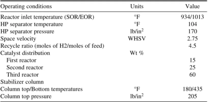
Operating Conditions
Reforming catalyst is a high-purity alumina catalyst impregnated with platinum and other noble metals. Reforming reactions are favored by high temperature and low pressure. The yield of reformate is a function of feed PONA and process severity. Typical operating conditions, feed, and product properties are shown in Tables 2-11 and 2-12. Motor gasoline blends typically contain 30 vol % or more reformate. Considering the large volumes of motor gasoline blended, the volumes of heavy naphtha feedstock consumed are a significant fraction of total naphtha production.
TABLE 2-11 Catalytic Reformer Operating Conditions
Operating conditions Units Value
Reactor inlet temperature (SOR/EOR) °F 934/1013
HP separator temperature °F 104
HP separator pressure lb/in2 170
Space velocity WHSV 2.75
Recycle ratio (moles of H2/moles of feed) 4.5
Catalyst distribution Wt %
First reactor 15
Second reactor 25
Third reactor 60
Stabilizer column
Column top/Bottom temperatures °F 180/435
Column top pressure lb/in2 205
TABLE 2-12 Catalytic Reformer Feed and Product Properties
Reformate
Property Units Feed C5+
API gravity ° 61.3 47.8
Specific gravity 0.734 0.789
Octane number 38 96
TBP distillation °F
IBP 194 140
10% 203
30% 221 194
50% 239 230
70% 257 257
90% 275
FBP 284 311
PONA Vol %
Paraffins 69
Naphthenes 20
Aromatics 11
Sulfur Wt % 0.015
Mercaptan Wt % 0.008
Nitrogen ppm 1.00
Aromatics Production
NAPHTHA 27
used for the manufacture of terephthalic acid (TPA) and dimethyl terephthalate (DMT). Both TPA and DMT are used in the manufacture of polyethylene terephthalate (PET) resin. The major uses of PET are fiber, film, and engineering resins.
The catalytic reforming of naphtha is also used for the production of aromatics such as benzene, toluene, and xylenes (Fig. 2-7). The only difference from the cat reformer for motor gasoline (mogas) is that reforming operations are carried out at a higher severity (98 to 102) in a continuous catalyst regeneration configuration. Feed is 183 to 313°F cut. It is used for the production of ben-zene, toluene, and mixed xylenes. Aromatics from reformate are separated from nonaromatics by solvent extraction. Aromatic extract is separated into benzene, toluene, and xylene by fractionation or other separation processes. Because there is little demand for toluene, it is converted to benzene by a hydrodealkylation process.
Fertilizer/Petrochemical Industry
Naphtha is used as a feedstock for the manufacture of nitrogen fertilizers such as urea, ammonium nitrate, ammonium sulfate, and so on. In regions where natural or associated gas is not available, naphtha is the preferred feedstock. Naphtha is also used for the manufacture of methyl alcohol with a large industrial demand.
Naphtha is gasified and next reacted at high tem-peratures (1575°F) with steam over a nickel catalyst that converts naphtha to carbon monoxide and hydro-gen (Fig. 2-8). Carbon monoxide reacts with more steam to produce more hydrogen and carbon dioxide. Hydrogen is reacted with nitrogen from the air to ammonia. Ammonia in turn is reacted with CO2to manufacture urea. Methanol is manufactured by react-ing carbon monoxide with hydrogen over a catalyst.
Naphtha Steam Cracker
Naphtha is one of the basic raw materials for the production of ethylene and propylene. Ethylene is the largest volume petrochemical produced worldwide (estimated at 95 million tons in 2002). Ethylene has no direct use but is used exclusively as a chemical building block. Ethylene, propy-lenes, and C4 olefins are used for the production of plastics, fibers, films, textiles, pharmaceuticals, detergents, and so on.
The bulk of the worldwide commercial production of olefin is based on the thermal cracking of naphtha or heavier hydrocarbons with steam. The process is called pyrolysis, or steam cracking.
Catalytic reformer
Aromatic
extraction Toluene Hydrodealkylation
Xylenes C9 + Aromatics
Benzene
Mixed xylenes Naphtha
feed
Steam reforming reaction
C5H12 + 5 H2O = 5 CO + 11 H2
CO + H2O = CO2 + H2 Low-temperature shift reaction
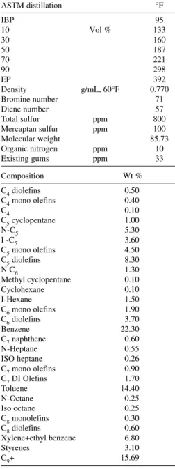
Naphtha is pumped through the convection section of the pyrolysis furnace where it is heated by heat exchange with flue gases. It is then mixed with steam and further heated to incipient crack-ing temperature (approximately 950°F) dependcrack-ing on feedstock. This stream next enters the radiant heating section of the furnace where it is heated under controlled conditions (residence time and temperature profile) to 1380 to 1607°F for 0.1 to 0.5 seconds. Final heating temperature depends on feed properties. Pyrolysis converts heavier hydro-carbons into lighter fractions, primarily ethylene and propylene, by removing hydrogen. Ethylene yield is roughly 33 wt % of the naphtha feed. The hot gas effluent from the furnace is then passed through a quench section where it is rapidly cooled to retard further cracking and to condense heavy fractions. Heavy fractions are subsequently processed into fuel oil, light cycle oil, and pyroly-sis gasoline. The pyrolypyroly-sis gasoline produced from naphtha cracker has a high benzene, toluene, and xylene content (Table 2-13). It also has a high olefin and diolefin content. It is first hydrotreated to saturate diolefins and monolefins. Aromatics are next extracted by a selective solvent such as sulfolane and separated by fractionation. Steam generated in the quench section is recycled back to the furnace for reuse.
Power Plant Fuel
Naphtha is increasingly being used as a fuel in gas-based power plants in place of natural gas, associated gas, or liquefied natural gas (LNG). Naphtha as a fuel cannot compete with natural gas due to its higher price, but because of the shortage of natural gas feedstock, power producers in many regions of the world use naphtha as fuel to meet electric power output requirements. Naphtha with high aromatic content (less than 20 vol %) can be used. Net heat of combustion is 20,000 Btu/lb or 11,300 kcal/kg, which is much more than natural gas on a per unit volume basis. Using naphtha in place of gas requires adjustment of operating con-ditions to avoid high boiler temperatures of 2000°F or more. Also, use of naphtha results in higher corrosion rates due to the sulfur in naphtha, which in turn causes shorter run length or more plant maintenance.
28 PETROLEUM FUELS
TABLE 2-13 Pyrolysis Gasoline Properties and Composition Ex Naphtha Steam Cracker
ASTM distillation °F
C4mono olefins 0.40
C4 0.10
C5cyclopentane 1.00
N-C5 5.30
I -C5 3.60
C5mono olefins 4.50
C5diolefins 8.30
N C6 1.30
Methyl cyclopentane 0.10
Cyclohexane 0.10
I-Hexane 1.50
C6mono olefins 1.90
C6diolefins 3.70
Benzene 22.30
C7naphthene 0.60
N-Heptane 0.55
ISO heptane 0.26
C7mono olefins 0.90
CHAPTER 3
GASOLINE
Gasoline may be defined as the fuel derived from crude oil, in the boiling range of 100 to 400°F, for use in spark-ignited internal combustion engines. Gasoline is one of the most important petroleum products. Most passenger cars use gasoline as fuel, and the demand for gasoline is directly linked to the growth of the automobile industry. It is estimated that production of gasoline worldwide in 2007 was approximately 1150 million tons, which corresponds to an estimated 27 percent gasoline yield from crude oil. The automobile industry is witnessing explosive growth. In 2006, estimated produc-tion of passenger cars was 49 million units, and demand for gasoline is growing in proporproduc-tion to the number of automobiles fueled by motor gasoline (mogas) on the roads. About half a century ago, gasoline was also a fuel for aircraft, but with the advent of aviation turbine engines, most military and commercial aircraft switched to kerosene fuel, and demand for gasoline for this use almost dis-appeared. However, a small number of piston engine aircrafts for commercial and military use still use gasoline fuel.
GASOLINE ENGINE
The gasoline engine is an internal combustion engine. Fuel is supplied by a pump from the automobile fuel tank. Gasoline is mixed with air, and the gasoline-air mixture enters the cylinder during the intake stroke. It is compressed by a piston on the compression stroke and ignited by a spark plug. As the fuel burns, the expanding hot gases force the piston down on the power stroke. Unburned gases are finally ejected from the cylinder on the exhaust stroke through an exhaust valve.
The stoichiometric ratio of air to fuel for complete combustion is 15:1 by weight. A richer mixture is used under full throttle where maximum power is desired. Gasoline is a mixture of hydrocarbons. In a perfect combustion process, oxygen in the air would convert all hydrocarbons to carbon dioxide and water, releasing energy for moving the car. In actual practice, the combustion process produces many types of pollutants that are emitted from the tailpipe of the automobile: unburned hydrocarbons, nitrogen oxides, carbon monoxide, and carbon dioxide.
GASOLINE PROPERTIES
Octane Number
The octane number is a relative measure of knocking, or the tendency to self-ignition of a fuel in a spark-ignited internal combustion engine. In a normal cycle, the fuel-air mixture is ignited at the end of the compression stroke by a spark plug. If fuel has too low an octane number, it may spontaneously ignite during the compression stroke itself due to the temperature rise during adi-abatic compression or from hot spots in the engine. This kind of ignition, called preignition, can quickly damage the engine. Fuels with a high normal paraffin content have a low octane and can cause preignition. The efficiency of an engine is directly proportional to its compression ratio; the higher the compression ratio, the higher the power output. For higher compression ratio