Contributing to Progress in the World of
Product Manufacture
NACHI-FUJIKOSHI CORP.
is a pioneer of precision cutting tools in Japan and one
of the leading manufacturers of tools worldwide. No manufacturer of cutting tools anywhere in
the world exercises greater control over the quality of its products than NACHI. NACHI quality starts with the
material itself because the High Speed Steel, premium Cobalt High Speed Steel, Powder High Speed, and
Cermet we use comes from our own mills. The technology of the coating, such as Mixed Component
multi-layer coating and Diamond coating (thin film diamond) has been developed specifically for our cutting tools.
Cutting tools are basic products for the machine industries. Successful performance of machine tools cannot be
expected without precise cutting tools and high quality. NACHI pursues the highest quality 100% of the time.
NACHI is the first Japanese cutting tool manufacturer to be awarded the prestigious honor of the Deming Award
for Quality.
When you purchase cutting tools from NACHI you are using products produced by one of the largest, most
innovative manufacturers of industrial equipment in the world. Established more than 75 years ago, The
NACHI-FUJIKOSHI CORP. has grown into a world-class, worldwide leader in its industry. The company has
approximately ten million square feet of plant area and facilities in Japan, Production plants in The U.S.A.,
Singapore, Brazil, Taiwan, Spain and Korea, and sales marketing subsidiaries in all major industrial nations.
The NACHI Difference:
NACHI-FUJIKOSHI CORP.
Head Office: Toyama Plant
Higashi - Toyama, Steel Plant Namerikawa Plant
Brazil Plant
JAPAN MAIN OFFICE
Shiodome Sumitomo Bldg. 17F, 1-9-2 Higashi-Shinbashi, Minato-ku, Tokyo JAPAN, 105-0021
Phone: (03)5568-5111 Fax: (03)5568-5206
Overseas Subsidiary Companies NACHI AMERICA INC.
HEADQUARTERS
713 Pushville Road, Greenwood, Indiana 46143, U.S.A. Phone: (317)530-1001 Fax: (317)530-1011
NACHI CANADA INC.
89 Courtland Ave., Unit No. 2, Concord, Ontario L4K 3T4, CANADA Phone: (905)660-0088 Fax: (905)660-1146
NACHI MEXICANA, S.A. DE C.V.
Urbina No.54, Parque Industrial Naucalpan, Naucalpan de Juarez, Estado de Mexico C.P. 53370, MEXICO
Phone: +52-55-3604-0832/0842/0081 Fax: +52-55-3604-0882
NACHI EUROPE GmbH
Bischofstrasse 99, 47809, Krefeld, GERMANY Phone: (02151)65046-0 Fax: (02151)65046-90
NACHI TECHNOLOGY (THAILAND) CO., LTD.
5/5 M, 2, Rojana Industrial Estate Nongbua, Ban Khai, Rayong, 21120, THAILAND Phone: (38)961-682 Fax: (66)38-961-683
NACHI SINGAPORE PTE. LTD.
No. 2 Joo Koon Way, Jurong Town, Singapore 628943, SINGAPORE
Phone: 65587393 Fax: 65587371
NACHI (SHANGHAI) CO., LTD.
Yitong Industry Zone 258, Fengmao Rd. Malu Town, Jiading, Shanghai 201801, CHINA
Phone: +86-(0)21-6915-2200 Fax: +86-(0)21-6915-5427
NACHI (AUSTRALIA) PTY. LTD.
(SYDNEY HEAD OFFICE)
Unit 1, 23-29 South Street, Rydalmere, N.S.W. 2116, AUSTRALIA Phone: (02)9898-1511 Fax: (02)9898-1678
FUJIKOSHI-NACHI (MALAYSIA) SDN. BHD.
No. 17, Jalan USJ 21/3, 47630 UEP Subang Jaya, Selangor Darul Ehsan, MALAYSIA Phone: 03-80247900 Fax: 03-80235884
Overseas Plants NACHI TECHNOLOGY INC.
713 Pushville Road, Greenwood, Indiana 46143, U.S.A. Phone: (317)535-5000 Fax: (317)535-8484
NACHI TOOL AMERICA INC.
713 Pushville Road, Greenwood, Indiana 46143, U.S.A. Phone: (317)535-0320 Fax: (317)535-0983
NACHI BRASIL LTDA.
Avenida joa~o XXIII, No. 2330, Jardim Sa~o Pedro,
Mogi das Cruzes, S.P., BRASIL, CEP 08830-000 Caixa Postal 2505 Phone: (011)4793-8800 Fax: (011)4793-8870
NACHI INDUSTRIES PTE. LTD.
No. 2 Joo Koon Way, Jurong Town, Singapore 628943, SINGAPORE Phone: 6861-3944 Fax: 6861-1153
NACHI PILIPINAS INDUSTRIES, INC.
1ST Avenue, Manalac Compound, Sta. Maria
Industrial Estate, Bagumbayan, Taguig Metro Manila, PHILIPPINES Phone: (02) 838-3620 Fax: (02) 838-3623
We have a history of Seventy five years as a world-famous integrated manufacturers with the renowned brand
“NACHI”. With the continuous production system, from high class special steels to finished products, our
well-coordinated technics stand high in public estimation.
2
THE NACHI DIFFERENCE --- MATERIAL AND HEAT TREATMENT
T
echnical
Data
DRILLS
DRILLS
Cutting Condition
END MILLS
END MILLS
Cutting Condition
T
APS
T
APS
Cutting Condition
Others
Material and heat treatment are major
factors in determining the performances
of the HSS tool. To provide high-quality
HSS tools, NACHI-FUJIKOSHI has a steel
mill to manufacture the HSS steels
con-forming to individual requirements for
our in-house use as well as for outside
sales.
Main high-speed tools and their applications
Electric arc furnace
Horizontal type one chamber gas pressure
quenching vacuum furnace
In the field of heat treatment, we are
pro-ducing and marketing vacuum heat
treat-ment furnaces, which are highly
evalu-ated among users both in Japan and
abroad. Further, through technical tie-ups
with Sumitomo Electric Industries Co.,
Ltd., we use cemented carbide materials
best suited to individual requirements.
High-speed tool
Clean Steel
Clean Heat Treatment
SKH10
SKH51
—
—
SKH55
SKH57
SKH59
SKS 7
SKD11
SKD61
High-speed
steel
Powdered
High-speed
steel
Alloy tool
steel
Steel type symbol
Chemical component
Application
JIS
T 15
M 2
M33
M34
M35
—
M42
AISI
HS55T
SKH51
HM33
HM34
HS53M
HS93R
HS96H
HS97R
FAX18
FAX31
FAX38
FAX55
FAX90
SKS 7
SKD11
SKD61
NACHI
1.5
0.85
0.9
0.9
1.05
1.25
1.1
1.1
1.1
1.3
1.3
1.6
2.6
1.15
1.5
0.4
C
5
9.5
8
5.5
3.5
9.5
5.5
9.5
5.5
5
3.5
1
1.3
Mo
12
6
1.5
2
6
10
1.5
7.5
1.5
6
6
12
10
2.2
W
4
4
4
4
4
4
4
4
4
4
4
4
4
0.3
12
5
Cr
5
2
1.2
2
2.5
3.5
1.2
1.8
1.2
3
3
5
8.5
0.4
1
V
5
8
8
5
10
8
9
8
8
5
10
Sil
Basic steel type, cutting tool
Drill, broach, others in general
Drill, gear cutting tool, others in general
Cutting tool, others in general
Cutting tool, others in general
Tool material
End milling cutter and others
End milling cutter, tap
Saws and others
General
Gear cutting tool, tap, others in general
Gear cutting tool, broach, others in general
General (high alloy material)
Hack saw, etc.
Molding tools including dies and molds
Co
Classification
W : Hard double carbide is formed to ensure improved
wear resistance
Mo : Fine carbide and improved toughness to ensure
improved wear resistance
Cr : Tissue stabilization factor (upgraded solubility)
Effects pf major alloy components
V
: Extended and improved wear resistance of
sec-ondary carbon
C
: Enhanced carbon formation factor and hardening
properties
3
T
echnical
Data
DRILLS
DRILLS
Cutting Condition
END MILLS
END MILLS
Cutting Condition
T
APS
T
APS
Cutting Condition
Others
THE NACHI DIFFERENCE --- MATERIAL AND HEAT TREATMENT
It is important that tool materials are characterized by
excellent resistance to chipping or breakage.
Selection is made from among various types of tool
materials in conformity to the workpiece and
machin-ing method. NACHI's integrated production system
covering the entire range from materials to tool
pro-duces provides tool materials meeting each of your
requirements.
Characteristic of various tool materials
Characteristics of various tool materials
Diamond sintered body
CBN sintered body Ceramic
W
ear resistance (or hardness)
Cutting speed
Thermit
Direction of development
Coated cemented carbide
Cemented carbide
Cutting conditions
Tool characteristics Toughness
Coated high seed steel
High seed steel Cemented carbide
of fine particle Powdered high
speed steel Feed
Carbon tool steel
Alloy tool steel
High speed steel
Powdered
high speed steel
Cemented carbide
Ultrafine grain
cemented carbine
Thermit
Ceramic
CBN sintered body
Diamond
sintered body
SK
첸
SKS
첸
SKD
첸
SKH
첸
NACHI symbol
FAX
첸
K
첸
P
첸
Z
첸
NACHI symbol
NAX
첸
NACHI symbol
BM
첸
BC
첸
NACHI symbol
DM
첸
Symbol
Type
(Example)
Production method
Features
SK 3
SKS 7
SKD 11
SKH 51
SKH 55
FAX 38
FAX 55
K 10
P 20
Z 20
NAX T
NAX LL
BM 10
BC 30B
DM 10
DM 10F
Tool steel where carbon is put into
iron to enable hardening.
Tool steel with its wear resistance improved
by alloy steel such as iron, Cr and W.
Tool steel with wear resistance and toughness
improved by hard carbide created by mixing
W, Mo, Cr and V with iron.
Fine powder of the high speed steel sintered by the powder
metallurgy. This method can also be used to manufacture
the type of steep containing such components as V and Co.
The major component is W. It is manufactured by sintering the TiC,
TaC and Co (bonding agent) according to powder metallurgy method.
Cemented carbide characterized in that the particle diameter
of carbide such as W, Ti and Ta does not exceed 1 micron.
The main components are carbide such as Ti and Ta,
nitride and carbonitride. They are sintered with Ni and
Co (binder) by powder metallurgy to produce Thermit.
A sintered body (porcelain). Available
in two types; alumina type mainly
consisting of Al2O3 and silicon
type mainly consisting of Si2N4.
Manufactured by sintering the powder of CBN, the hardest
second only to diamond, at a high temperature under super
high pressure. Excellent hardness even at a high temperature.
A polycrystalline body formed by sintering powdered
diamond at a high temperature under super high
pressure. Characterized by excellent hardness.
Less expensive, but low hardness
at a high temperature.
The steel type with much Co content is
called cobalt high speed tool characterized
by excellent heat resistance.
The tissue is minute, uniform and tough.
Further, excellent wear resistance is
provided by such components.
Very hard at a high temperature and excellent
in wear resistance, but chips easily.
The toughness is higher than that of cemented
carbide, but wear resistance is lower.
Excellent in resistance to wear, heat and
deposition, but susceptible to chipping.
Used for high-sped cutting.
Excellent wear resistance but
poor toughness.
Reaction with metal occurs very
rarely. Characterized by excellent
stability at a high temperature.
Chemically stable to the workpiece
made of other than iron.
0 Diamond
Hardness of high-hardness material
CBN TiC TiN WC Cemented carbide High seed steel
1000 2000 3000
Vickers hardness
4000 5000 10000
4
THE NACHI DIFFERENCE --- COATING TECHNOLOGY
T
echnical
Data
DRILLS
DRILLS
Cutting Condition
END MILLS
END MILLS
Cutting Condition
T
APS
T
APS
Cutting Condition
Others
Coating Series with Excellent Characteristics
High-speed dry machining of aluminum alloy
has been realized by adoption of cemented
carbide alloy and coating of DLC
(Diamond-Like Carbon) -- an amorphous substance
having diamond-like properties characterized
by a high degree of hardness, a low friction
coefficient and wear resistance.
It has a low friction coefficient and resistance
to deposition of aluminum alloy. Deposition
is reduced even in high-speed dry
machin-ing, and excellent properties of machining
surfaces are provided.
DLC Coating
As a cutting tool coating technique, this
coat-ing technique provides improved wear
resist-ance and ensures protection of the base
materials (through the use of a composite
multi-layer configuration), centering on the
general-purpose TIN G-series. We have
established the manufacturing conditions of
various series of our company, including the
SG series of high-speed steel.
Composite multi-layer coating
We are the first in the world to succeed in
commercial use of a diamond film (so-called
a tool of dream), using our coating
tech-nique.
Diamond coating by vapor phase synthetic
method provides the close adhesion that has
been inconceivable so far. The technique
ensures drastic improvement of cutting
perform-ance in the field of machining the nonferrous
metal, graphite, composite material or
alu-minum alloy.
Diamond coating
Our R & D efforts cover the development of
coating equipment indispensable to the
developing of new coating technology.
Coating equipment
Graphite DLC Diamond
Graphite amorphous Diamond
C C+H C
— 1000~8000HV 10000HV
element R/V
Structure
Construction of DLC
High wear resistance film Iubrication film (DLC)
Body
1.0
0.0 0.1 0.2 0.3 0.4 0.5 0.6 0.7 0.8 0.9
Frictional coefficient
0 2000 4000 6000 800
Rotation of disk
DLC CrN TiN
BALL : SUJ2 Disk : Film/HSS (Ry0.2µm)
Revolution : 500RPM Over weight : 100N Dry
Machine : CSEM Tribometer
Composite multi-layer film (UG-Coating) Base material
Diamond coated film
5
T
echnical
Data
DRILLS
DRILLS
Cutting Condition
END MILLS
END MILLS
Cutting Condition
T
APS
T
APS
Cutting Condition
Others
THE NACHI DIFFERENCE --- COATING TECHNOLOGY
Comparison of characteristics of NACHI coating film
Name
Evaluation of relative
characteristics
Features
G
(TiN)
SG
UG
AG
X's
AQUA
DLC
DIA
- The basis for PVD coating.
Coating method in common use.
- Composite multi-layer film coating method
character-ized by improved wear resistance as compared to TiN.
- Coating method characterized by adoption of a TiCN
based composite multi-layer film to provide improved
wear resistance.
- Coating method based on the TiAIN film characterized
by superb resistance to heat and wear.
Commercialized for use in high-speed steel.
- Coating method for cemented carbide end-milling
cut-ters, based on the TiAIN film characterized by superb
resistance to heat and wear.
- Coating method characterized by excellent heat
resist-ance and lubricity of the workpiece. Compatible with
both dry machining and wet machining.
- Coating method characterized by a film having a
structural characteristic intermediate between
graphite and diamond, where the surface is provided
with a smooth film, thereby enhancing resistance of
aluminum alloy and others to deposition.
- Coating method best suited to processing of
non-ferrous metal, graphite and aluminum alloy, where
NACHI is the first to realize commercialization of a
dia-mond film.
0 1 2 3 4 5 Wear resistance
Toughness
Heat resistance Deposition resistance
(for iron) Surface properties (Smoothness)
G
0 1 2 3 4 5 Wear resistance
Toughness
Heat resistance Deposition resistance (for iron) Surface properties (Smoothness)
G SG
0 1 2 3 4 5 Wear resistance
Toughness
Heat resistance Deposition resistance (for iron) Surface properties (Smoothness)
G UG
0 1 2 3 4 5 Wear resistance
Toughness
Heat resistance Deposition resistance (for iron) Surface properties (Smoothness)
G AG
0 1 2 3 4 5 Wear resistance
Toughness
Heat resistance Deposition resistance (for iron) Surface properties (Smoothness)
G X's
0 1 2 3 4 5 Wear resistance
Toughness
Heat resistance Deposition resistance (for iron) Surface properties (Smoothness)
G AQUA
0 1 2 3 4 5 Wear resistance
Toughness
Heat resistance Deposition resistance (for aluminum) Surface
properties (Smoothness)
G DLC
0 1 2 3 4 5 Wear resistance
Toughness
Heat resistance Deposition resistance (for aluminum) Surface
properties (Smoothness)
6
THE NACHI DIFFERENCE --- ECO & ECO CONCEPT
T
echnical
Data
DRILLS
DRILLS
Cutting Condition
END MILLS
END MILLS
Cutting Condition
T
APS
T
APS
Cutting Condition
Others
NACHI’s Efficiency Theme “Eco & Eco”
Sets The New Standard for Cutting Tools
“ ECO ” = Economy of Cost Reduction
“ ECO ” = Ecologically Friendly
Achieving The Cost Efficient Environmentally Friendly Solution
Economical
Environmentally
manufacturing
Reduction of
Energy
Consumption
Reduction of
Coolant oil
High Speed & Feed
Dry & Semi-Dry
Cutting
NACHI’s Efficient Eco & Eco Lines
Dry & Semi-Dry Cutting
Drilling
AQUA Drill Series
for Steel
DLC Drill Series
for Aluminum
Milling
DLC Endmill Series
for Aluminum
X's mill GEO Series
for Steel
X's mill Series
for Steel
7
T
echnical
Data
DRILLS
DRILLS
Cutting Condition
END MILLS
END MILLS
Cutting Condition
T
APS
T
APS
Cutting Condition
Others
THE NACHI DIFFERENCE --- ECO & ECO CONCEPT
If you can reduce coolant use,
you can reduce cost by more than 16%
Tool cost
4 %
Others
80 %
Coolant cost
16 %
The "Dry" Advantages
• No Coolant Expense
• Reduced Energy Consumption
• Reduced Cleaning Effort
Reducing Machining Costs
The Machining Energy Story
Machining energy
= Working energy
Static energy
1 cycle
Machining energy
= Working energy
Static
energy
1 cycle
E
n
e
r
g
y
Reduced Machining Time
Reduce Working and Static Energy
Less Energy = High Speed Efficient Cutting
( High Speed & Feed Cutting )
The NACHI Solution
High Speed
& Feed Cutting
NACHI High Speed & Feed Lines
Drilling
AQUA Drill Series
for Steel
AG /UG Power Series
for Steel
Milling
X's mill GEO Series
X's mill Series
High Speed and Feed Cutting
T
echnical
Data
DRILLS
DRILLS
Cutting Condition
END MILLS
END MILLS
Cutting Condition
T
APS
T
APS
Cutting Condition
Others
G (TiN) Coating Normal Helix Flutes
High Helix Flutes
Low Helix Flutes
Point Angle of Drills
Drill Length is from Center Point
Drill Length is from Corner Point
Oil-hole Drills
Three Flutes Drills
Shape of Lip Relief is Conical
Shape of Lip Relief is Two Rake
Shape of Lip Relief is Three Rake
S-type Thinning
Notch Thinning
X-type Thinning
XH-type Thinning
2Rake Relief & X-type Thinning
2Rake Relief & XR-type Thinning
3 Flutes Drills & 3F-type Thinning UG (TiCN multi layer) Coating
SG (TiCN multi layer) Coating
AG (TiAlN multi layer) Coating
AQ (TiAlN multi layer) Coating
X's (TiAlN multi layer) Coating
GS (TiAlN multi layer) Coating
DLC Coating
Diamond Coating
High Speed Steels
Cobalt High Speed Steels
Fine Melting HSS
High Grade Powder HSS
Vanadium HSS
Vanadium HSS
Cobalt/Vanadium HSS
Tungsten Carbide
Coating
Flutes of Drills
Drill Dimension
Lip Relief of Drills
Thinning of Drills
T
ool Materials
T
echnical
Data
DRILLS
DRILLS
Cutting Condition
END MILLS
END MILLS
Cutting Condition
T
APS
T
APS
Cutting Condition
Others
Tolerance of Drills Diameter is js6 4 Flutes Radius End mills (Center Cut)
2 Flutes Ball Nose End mills (Center Cut)
4 Flutes Ball Nose End mills (Center Cut)
6 Flutes Ball Nose End mills (Center Cut)
Cutting Taps
Forming Taps
Straight Flutes Taps
Spiral Pointed Taps
Normal Helix Flutes Taps
High Helix Flutes Taps
Low Helix Flutes Taps
Chamfer Length is 2.5P to 3P
Chamfer Length is 4P to 5P (for through hole)
Chamfer Length is 1.5P (for blind hole)
Chamfer Length is 2.5P
Chamfer Length is 3.5P
Cutting Taps for Taper Pipe Tolerance of Drills Diameter is h7
Tolerance of Drills Diameter is h8
Sharp corner Type End mills
2 Flutes Square End mills (Center Cut)
3 Flutes Square End mills (Center Cut)
4 Flutes Square End mills (Center Cut)
4 Flutes Square for X's-mill Hard (Center Cut)
5 Flutes Square End mills (Center Cut)
6 Flutes Square End mills (Center Cut)
6 Flutes Square for X's-mill Hard & X's-mill Multi Flutes (Center Cut)
8 Flutes Square for X's-mill Hard & X's-mill Multi Flutes (Center Cut)
4 Flutes Square End mills (with Center Hole)
5 Flutes Square End mills (with Center Hole)
6 Flutes Square End mills (with Center Hole)
Multiple Flutes (over 8) Square End mills (with Center Hole)
2 Flutes Radius End mills (Center Cut)
T
olerance of Drills Dia.
Flutes of End Mills
Flutes of End Mills
T
ype of
T
aps
Flutes of
T
aps
Chamfer of
T
aps
Drills / Visual Index
T
echnical
Data
DRILLS
DRILLS
Cutting Condition
END MILLS
END MILLS
Cutting Condition
T
APS
T
APS
Cutting Condition
Others
HIGH PERFORMANCE DRILLS
List 7573P
STUB LENGTH SG-ESS / FRACTIONAL, WIRE, LETTER
P52
P
100
List 7570P
JOBBERS LENGTH SG-ES / METRIC SIZES
P53
P
100
List 7571P
JOBBERS LENGTH SG-ES / FRACTIONAL, WIRE, LETTER
P54
P
100
List 7596P
SG DRILLS WITH OIL-HOLE
P55
P
101
Metric Sizes
List 7591P
Fractional
List 6540P
AG-POWER LONG DRILLS
P61
P
102
Metric Sizes
List 6541P
Fractional
List 6517U
UG POWER DRILLS / FRACTIONAL SIZES
P56
P
101
List 6528P
UG POWER DRILLS / METRIC SIZES
P57
P
101
List 6596P
AG-SUS DRILLS SHORT / METRIC SIZES
P58
P
102
List 6594P
AG-SUS DRILLS REGULAR / METRIC SIZES
P59
P
102
List 6595P
AG-SUS DRILLS REGULAR / FRACTIONAL SIZES
P60
P
102
List 7572P
STUB LENGTH SG-ESS / METRIC SIZES
P48
P
100
>1.9>1.9
T
echnical
Data
DRILLS
DRILLS
Cutting Condition
END MILLS
END MILLS
Cutting Condition
T
APS
T
APS
Cutting Condition
Others
Drills / Visual Index
List 9550
AQUA DRILLS STUB / METRIC SIZES
P63
P
103
List 9551
AQUA DRILLS STUB / FRACTIONAL
P64
P
103
List 9552
AQUA DRILLS REGULAR / METRIC SIZES
P65
P
104
List 9558
AQUA DRILLS WITH MIST-HOLE 3D
P66
P
106
List 9554
AQUA DRILLS WITH MIST-HOLE 5D
P67
P
106
List 9546
AQUA DRILLS THREE FLUTES / METRIC SIZES
P69
P
104
List 9548
AQUA DRILLS HARD / METRIC SIZES
P70
P
105
List 9544
AQUA MICRO DRILLS / METRIC SIZES
P71
P
105
List 9556
AQUA DRILLS WITH MIST-HOLE 7D
P68
P
107
Metric Sizes
List 9569
Fractional
List 9588
VG OIL HOLE DRILL FOR 3D
P72
P
108
Metric Sizes
List 9589
Fractional
List 9586
VG OIL HOLE DRILL FOR 5D
P74
P
108
Metric Sizes
List 9587
Fractional
List 9566
MQL PILOT DRILLS
P76
P
110
NEW
NEW
Drills / Visual Index
T
echnical
Data
DRILLS
DRILLS
Cutting Condition
END MILLS
END MILLS
Cutting Condition
T
APS
T
APS
Cutting Condition
Others
STRAIGHT SHANK JOBBERS LENGTH DRILL / LETTER SIZES
List 501
General Purpose
P86
P
112
List 501A
General Purpose
P86
P
112
List 6501
Aircraft NAS907-J
P86
P
112
STRAIGHT SHANK DRILLS
List 500
STRAIGHT SHANK JOBBERS LENGTH DRILL / METRIC SIZES
P82
P
112
>0.55 >13.0List 6520
STRAIGHT SHANK COBALT DRILL TYPE
!
/ METRIC SIZES
P83
P
112
>1.5List 520P
G STANDARD DRILLS / METRIC SIZES
P84
P
112
>3List 9501D
DIAMOND COATED CARBIDE DRILLS
P78
P
107
List 544
DLC-HSS DRILLS / METRIC SIZES
P79
P
111
>1.4List 9524
DLC MICRODRILLS / METRIC SIZES
P80
P
111
List 9520
DLC DRILLS REGULAR / METRIC SIZES
P81
P
111
MQL POWER LONG DRILLS
P77
P
109
List 9564
10D
T
echnical
Data
DRILLS
DRILLS
Cutting Condition
END MILLS
END MILLS
Cutting Condition
T
APS
T
APS
Cutting Condition
Others
Drills / Visual Index
List 517P
Parabolic
P86
P
113
STRAIGHT SHANK JOBBERS LENGTH DRILLS / WIRE GAUGE SIZES
List 501
General Purpose
P86
P
112
List 501A
General Purpose
P86
P
112
List 501P
General Purpose
P86
P
112
SCREW MACHINE LENGTH / FRACTIONAL SIZES
List 561
General Purpose
P88
P
112
List 561P
General Purpose
P88
P
112
>1/2>#53
List 6501
Aircraft NAS907-J
P86
P
112
STRAIGHT SHANK JOBBERS LENGTH DRILLS / FRACTIONAL
List 501
P86
P
112
General Purpose
>1/2
List 501A
P86
P
112
General Purpose
>1/2
List 6501
P86
P
112
Aircraft NAS907-J
>5/64
List 501P
P86
P
112
General Purpose
>1/2
List 517P
P86
P
113
Drills / Visual Index
T
echnical
Data
DRILLS
DRILLS
Cutting Condition
END MILLS
END MILLS
Cutting Condition
T
APS
T
APS
Cutting Condition
Others
SCREW MACHINE LENGTH / LETTER SIZES
List 561
General Purpose
P88
P
112
List 563
Aircraft NAS907-C
P88
P
112
List 6563
Aircraft NAS907-C
P88
P
112
List 545P
Parabolic Style
P90
P
113
STRAIGHT SHANK TAPER LENGTH / FRACTIONAL SIZES
List 6531
General Purpose
P90
P
112
P90
P
112
List 531
General Purpose
>1/2
SCREW MACHINE LENGTH / FRACTIONAL SIZES
List 6563
Aircraft NAS907-C
P88
P
112
>#53List 563
Aircraft NAS907-C
P88
P
112
List 6563
Aircraft NAS907-C
P88
P
112
SCREW MACHINE LENGTH / WIRE GAUGE SIZES
List 561
General Purpose
P88
P
112
>5/64>5/64
List 561P
General Purpose
P88
P
112
List 563
Aircraft NAS907-C
P88
T
echnical
Data
DRILLS
DRILLS
Cutting Condition
END MILLS
END MILLS
Cutting Condition
T
APS
T
APS
Cutting Condition
Others
Drills / Visual Index
TAPER SHANK DRILLS
List 601
TAPER SHANK DRILLS / REGULAR SHANKS / FRACTIONAL
P94
P
115
>1/2List 651
EXTRA LENGTH DRILLS / TAPER SHANK DRILLS
P95
P
113
>1/2List 683
OIL HOLE DRILLS / TAPER SHANK
P96
P
115
List 581
OIL HOLE DRILLS / STRAIGHT SHANK
P93
P
114
STRAIGHT SHANK DRILL-EXTRA LENGTH
P92
P
113
List 551
Parabolic Tang Drive
List 6551
P92
P
113
List 575
SILVER AND DEMING DRILLS
P97
P
115
SPECIAL
>23/32
List 599
DRILL SETS / JOBBERS LENGTH
P98
Endmills / Visual Index
T
echnical
Data
DRILLS
DRILLS
Cutting Condition
END MILLS
END MILLS
Cutting Condition
T
APS
T
APS
Cutting Condition
Others
HIGH PERFORMANCE END MILLS
List 9382
GS-MILL TWO FLUTE
P
142
P
177
List 9384
GS-MILL FOUR FLUTE
P
142
P
177
List 9386
GS-MILL BALL
P
143
P
178
List 9398
GS-MILL HARD
P
144
P
179
List 9408
MOLD MEISTER BALL
P
143
P
184
List 9399
GEO-MILL HARD / INCH SIZES
P
145
P
180
List 9422
GS-MILL HARD BALL
P
144
P
181
List 9423
GEO-MILL HARD BALL / INCH SIZES
P
145
P
181
List 9322
X’S-MILL GEO / METRIC SIZES
P
146
P
182
List 9321
X’S-MILL GEO / INCH SIZES
P
147
P
182
List 9324
X’S-MILL GEO RADIUS
P
148
P
182
List 9338
X’S-MILL GEO SLOT
P
149
P
183
NEW
T
echnical
Data
DRILLS
DRILLS
Cutting Condition
END MILLS
END MILLS
Cutting Condition
T
APS
T
APS
Cutting Condition
Others
Endmills / Visual Index
List 9366
X’S-MILL GEO KV TWO FLUTES
P
150
P
186
List 9368
X’S-MILL GEO KV FOUR FLUTES
P
150
P
186
List 9332
X’S-MILL GEO MICROBALL
P
152
P
185
List 9330
DLC-MILL FOR ALUMINUM / METRIC SIZES
P
153
P
187
List 9378
DLC-MILL SHARP CORNER TWO FLUTE
P
153
P
187
List 9302
DLC-MILL RADIUS
P
154
P
187
List 9390
DLC-MILL SLOT LONG SHANK
P
155
P
187
List 9360
DLC-MILL BALL
P
156
P
190
List 6450
DLC-HSS MILL / METRIC SIZES
P
157
P
191
List 6231HD
DLC-HSS MILL / INCH SIZES
P
157
P
191
List 6485
AG-MILL ROUGHING / INCH SIZES
P
158
P
192
List 6403
AG-MILL HEAVY / INCH SIZES
P
158
P
193
List 9340
X’S-MILL GEO BALL
P
151
Endmills / Visual Index
T
echnical
Data
DRILLS
DRILLS
Cutting Condition
END MILLS
END MILLS
Cutting Condition
T
APS
T
APS
Cutting Condition
Others
END MILLS
List 9261X
GENAC END MILLS “SG” COATED CARBIDE
P
163
P
194
Regular
List 9271X
P
163
P
195
Ball Nose
List 9263X
P
163
P
194
Regular
List 9273X
P
163
P
195
Ball Nose
List 9221X
P
164
P
196
List 6486
AG-MILL ROUGHING MEDIUM
P
160
P
192
List 6488
AG-MILL ROUGHING LONG
P
160
P
192
List 6402
AG-MILL HEAVY
P
161
P
193
List 6404
AG-MILL HEAVY LONG
P
162
P
193
List 9251X
P
164
P
196
List 6406
AG-MILL ROUGHING SHORT
P
159
P
192
List 6484
AG-MILL ROUGHING REGULAR LENGTH SHORT
P
159
P
192
T
echnical
Data
DRILLS
DRILLS
Cutting Condition
END MILLS
END MILLS
Cutting Condition
T
APS
T
APS
Cutting Condition
Others
Endmills / Visual Index
List 9265X
GENAC END MILLS “SG” COATED CARBIDE LONG SERIES
P
165
P
194
List 9267X
P
165
P
194
List 9275X
P
165
P
195
List 9277X
P
165
P
195
List 6367
ROUGHING AND FINISHING (HEAVY DUTY) END MILLS
P
166
P
203
List 6367X
P
166
P
199
List 6303
ROUGHING (HOG) END MILLS
P
167
P
203
List 6303X
P
167
P
199
List 6307
P
168
P
203
List 231
TWO FLUTE END MILLS / REGULAR-SINGLE END
P
169
P
200
List 6231
P
169
P
200
Discontinued items
Discontinued items
Discontinued items
Endmills / Visual Index
T
echnical
Data
DRILLS
DRILLS
Cutting Condition
END MILLS
END MILLS
Cutting Condition
T
APS
T
APS
Cutting Condition
Others
List 6233
TWO FLUTE END MILLS / LONG, SINGLE END
P
170
P
200
TWO FLUTE END MILLS / REGULAR-SINGLE END
List 6231X
P
169
P
197
List 261
TWO FLUTE DOUBLE END MILLS
P
171
P
200
List 6230
METRIC SIZES, REGULAR, SINGLE END
P
172
P
200
List 6210
P
172
P
201
List 211
MULTI FLUTE END MILLS / REGULAR SINGLE END CENTER CUTTING
P
173
P
201
List 6211M
P
173
P
201
List 6211X
P
173
P
198
List 213
MULTI FLUTE END MILLS / LONG SINGLE END, CENTER CUTTING
P
174
P
201
List 6213
P
174
P
201
Discontinued items
Discontinued items
T
echnical
Data
DRILLS
DRILLS
Cutting Condition
END MILLS
END MILLS
Cutting Condition
T
APS
T
APS
Cutting Condition
Others
Endmills / Visual Index
FOUR FLUTE, DOUBLE END END MILLS
List 271
P
176
P
201
List 215
FOUR FLUTE END MILLS / EXTRA LONG SINGLE END, CENTER CUTTING
P
175
P
201
Discontinued items
Taps / Visual Index
T
echnical
Data
DRILLS
DRILLS
Cutting Condition
END MILLS
END MILLS
Cutting Condition
T
APS
T
APS
Cutting Condition
Others
List 6957
DLC TAFLET THREAD FORMING TAPS / MACHINE SCREW SIZES
P228
P
260
List 6955
DLC TAFLET THREAD FORMING TAPS / FRACTIONAL SIZE
P228
P
260
List 6956
DLC TAFLET THREAD FORMING TAPS / METRIC SIZES
P229
P
260
List 6959
SG LO-SPIRAL FLUTED TAPS / MACHINE SCREW SIZES & FRACTIONAL SIZE
P230
P
260
List 6958
SG LO-SPIRAL FLUTED TAPS / METRIC SIZES
P231
P
260
HIGH PERFORMANCE TAPS
List 7981
VIPER T SERIES-SPIRAL FLUTED / GENERAL PURPOSE
P233
P
260
List 7971
VIPER T SERIES-SPIRAL POINTED / GENERAL PURPOSE
P234
P
260
VIPER T-SERIES
VIPER T SERIES-METRIC TAPS / GENERAL PURPOSE
List 7980
Spiral Fluted
P235
P
260
List 7970
Spiral Pointed
P235
P
260
List 7987
VIPER T SERIES-SPIRAL FLUTED / FOR STAINLESS STEEL
P236
T
echnical
Data
DRILLS
DRILLS
Cutting Condition
END MILLS
END MILLS
Cutting Condition
T
APS
T
APS
Cutting Condition
Others
Taps / Visual Index
VIPER T SERIES METRIC TAPS / FOR STAINLESS STEEL
List 7982
Spiral Fluted
P238
P
260
List 7972
Spiral Pointed
P238
P
260
List 996
VIPER TAFLET METRIC TAPS FOR STEELS
P242
P
260
VIPER TAFLET
VTP TAPS
VTP SPIRAL FLUTED
List 983
Machine Screw Sizes
P244
P
260
List 981
Fractional Sizes
P244
P
260
VIPER TAFLET FOR STEELS
List 995
Machine Screw Sizes
P240
P
260
List 995
Fractional Sizes
P241
P
260
List 7977
VIPER T SERIES-SPIRAL POINTED / FOR STAINLESS STEEL
P237
Taps / Visual Index
T
echnical
Data
DRILLS
DRILLS
Cutting Condition
END MILLS
END MILLS
Cutting Condition
T
APS
T
APS
Cutting Condition
Others
VTP SPIRAL POINTED
List 973
Machine Screw Sizes
P245
P
260
List 971
Fractional Sizes
P245
P
260
VTP ROLL FORM TAPS
List 993
Machine Screw Sizes
P246
P
260
List 991
Fractional Sizes
P247
P
260
List 980
VTP METRIC TAPS SPIRAL FLUTED
P249
P
260
List 982
VTP METRIC TAPS SPIRAL POINTED
P249
P
260
STANDARD TAPS
STANDARD HAND TAPS
List 911
Fractional Sizes
P250
P
260
List 911P
Fractional Sizes
P250
P
260
List 913
Machine Screw Size
P251
P
260
List 913P
Machine Screw Sizes
P251
P
260
Discontinued items
T
echnical
Data
DRILLS
DRILLS
Cutting Condition
END MILLS
END MILLS
Cutting Condition
T
APS
T
APS
Cutting Condition
Others
Taps / Visual Index
STANDARD TAPS SPIRAL POINTED / FRACTIONAL SIZES
List 921
Fractional Sizes
P252
P
260
List 921S
Fractional Sizes
P252
P
260
List 921P
Fractional Sizes
P252
P
260
STANDARD TAPS SPIRAL POINTED / MACHINE SCREW SIZES
List 923
Machine Screw Sizes
P253
P
260
List 923S
Machine Screw Sizes
P253
P
260
List 923P
Machine Screw Sizes
P253
P
260
STANDARD TAPS / SPIRAL FLUTED
List 931
Fractional Sizes
P254
P
260
List 933
Machine Screw Sizes
P254
P
260
STANDARD TAPS / FAST SPIRAL FLUTED
List 931H
Fractional Sizes
P255
P
260
List 933H
Machine Screw Sizes
P255
P
260
List 969
STANDARD HAND TAPS / FOR CAST IRON
P252
P
260
Discontinued items
Discontinued items
Discontinued items
Taps / Visual Index
T
echnical
Data
DRILLS
DRILLS
Cutting Condition
END MILLS
END MILLS
Cutting Condition
T
APS
T
APS
Cutting Condition
Others
STANDARD TAPS / .005 OVERSIZED
List 915
Fractional Sizes & Machine Screw Sizes
P256
P
260
List 925
Fractional & Machine Screw Sizes
P256
P
260
TAPER PIPE TAPS / STRAIGHT FLUTED
List 941D
(NPTF)
P257
P
260
List 943
TAPER PIPE TAPS / INTERRUPTED
P257
P
260
TAPER PIPE TAPS / SPIRAL FLUTED
List 947
(NPT)
P258
P
260
List 947D
(NPTF)
P258
P
260
STRAIGHT PIPE TAPS / STRAIGHT FLUTED
List 945
(NPS)
P258
P
260
List 945D
(NPSF)
P258
P
260
TAPER PIPE TAPS / STRAIGHT FLUTED
List 941
(NPT)
P257
P
260
List 941P
(NPT)
P257
P
260
T
echnical
Data
DRILLS
DRILLS
Cutting Condition
END MILLS
END MILLS
Cutting Condition
T
APS
T
APS
Cutting Condition
Others
Taps / Visual Index
List 910
STANDARD METRIC HAND TAPS
P259
P
260
List 920
STANDARD METRIC TAPS / SPIRAL POINTED
P259
30
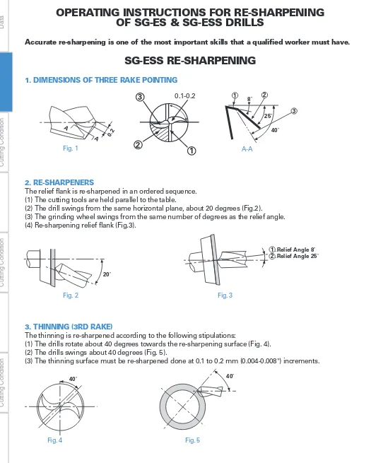
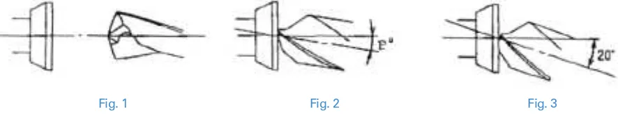
TECHNICAL INFORMATION / SG DRILLS
T
echnical
Data
DRILLS
DRILLS
Cutting Condition
END MILLS
END MILLS
Cutting Condition
T
APS
T
APS
Cutting Condition
Others
Composite multi-layer film coating method characterized by
improved wear resistance as compared to TiN.
0 1 2 3 4 5 Wear resistance
Toughness
Heat resistance Deposition resistance
(for iron) Surface properties (Smoothness)
TiN SG
Brand A (TiN Coated) SG-ES Drill
Positioning
30µm 15µm
SG-ESS Drills (stub length)
Self centering point:
SG-ES Drill
(jobber's length):
Characteristics of SG coating
Cutting condition
Drill Dia : 9.0mm.
Hole Depth : 32mm
Cutting Speed : 20m/min. (65.6 SFM)
Feed : 142mm/min (5.6 IPM)
Work piece Material : Alloy steel (300HB)
Machine : Vertical machining center
Brand A (TiN Coated) SG-ES Drill
0 0 25 20 15 10 5
100 200 300 400 500 600 Enlargement
Number of Drilled Holes (µm)
Performance and cutting
data of SG drill series
Structural Steels, Carbon Steels, Alloy Steels, Stainless Steels, Cast Irons,
Aluminum Alloys
• Streamline the process and reduce machining time dramatically.
• Eliminate the center drill operation with our SG-ESS drills (Stub length)
• Stable positioning within 0.0006" (15µm)
• Faster feed & speed rates than regular HSS-Co drills
• Better cost performance than carbide drills
• Utilizes a high accuracy shape of lip relief (3 rake, 2 rake + x-thinning)
• Made from premium powder metal with Composite Multi-Layer
SG Coating (TiCN)
• End mill style shanks for highly precise and accurate drilling
List No. Page
SG-ESS Drill/Metric Sizes SG-ESS Drill/Fractional Sizes SG-ESS Drill/Wire & Letter Sizes SG-ES Drill/Metric Sizes SG-ES Drill/Fractional Sizes SG-ES Drill/Wire & Letter Sizes SG-OH Drill/Fractional Sizes SG-OH Drill/Metric Sizes
7572P 7573P 7573P 7570P 7571P 7571P 7591P 7596P Drill Name
48 52 52 53 54 54 55 55
Stocked Size
Features
Work Materials
31
T
echnical
Data
DRILLS
DRILLS
Cutting Condition
END MILLS
END MILLS
Cutting Condition
T
APS
T
APS
Cutting Condition
Others
TECHNICAL INFORMATION / AG-SUS DRILLS
T
OOL
L
I
F
E
7 0 0 6 0 0 5 0 0 4 0 0 3 0 0 2 0 0 1 0 0 0
AG-SUS Regular Drill Brand B
Austenitic Stainless Steels, Martensitic Stainless Steels, Feritic Stainless Steels,
Structural Steels, Low Carbon Steels
• Utilizes a high accuracy shape of lip relief (3 rake thinning)
• Made from New HSS (FM-HSS: Fine melting HSS) with Composite
Multi-Layer AG Coating (TiAIN)
• End mill style shanks for highly precise and accurate drilling
List No. Page
AG-SUS Drill Short/Metric Sizes AG-SUS Drill Regular/Metric Sizes AG-SUS Drill Regular/Fractional Sizes
6596P 6594P 6595P Drill Name
58 59 60
Stocked Size
AG-SUS DRILL
COMPETITOR
CUTTING CONDITION
Drill Dia.: 6mm
Material: S42020 (SUS420J2)
Hole Depth: 20mm through
Speed: 78 SFM (1.275 rpm)
Feed: 190mm/min (7.48 IPM)
Pecking: Non
Coolant: Emulsion
NU
M
B
E
R
O
F
H
O
L
E
S
2 5 0 0 2 0 0 0 1 5 0 0 1 0 0 0 5 0 0 0
AG-SUS Regular Drill Brand C
CUTTING CONDITION
Drill Dia.: 1mm (0.039”)
Material: S304 (175 HB)
Hole Depth: 5mm blind
Speed: 49 SFM (4.775 rpm)
Feed: 100mm/min (3.94 IPM)
Pecking: 1mm
Coolant: Emulsion
CHIP
SHAPE-NACHI AG-SUS DRILL VS. COMPETITOR
FOR STAINLESS STEEL
To u g h n e s s H e a t R e s i s t a n c e W e a r R e s i s t a n c e M i c r o S t r u c t u r e
C o nv e n t i o n a l H S S Po w d e r M e t a l H S S F M - H S S
GOOD EXCELLENT
Features
Work Materials
32
TECHNICAL INFORMATION /
UG POWER DRILLS
T
echnical
Data
DRILLS
DRILLS
Cutting Condition
END MILLS
END MILLS
Cutting Condition
T
APS
T
APS
Cutting Condition
Others
JAPAN
STOCK ITEM
*
NU
M
B
E
R
O
F
H
O
L
E
S 1 5 0 0
1 0 0 0
5 0 0
0
U G P OW E R D R I L L OT H E R B R A N D
( Ti N C o a t e d )
1 0 8 6 h o l e s
5 6 3 h o l e s
Tool life is 1.5 times longer than competitor
UG Power Drills
Competitor
APPLICABLE MATERIAL
UNSUITABLE MATERIAL
• Carbon Steel
• Alloy Steel
• Tool Steel
• Die Steel
• Cast Iron
• Stabilized Steel (under 35HRC)
• Soft Steel
• Aluminum
• Copper Alloy
• Hardened Steel (over 40HRC)
New style Parabolic Drills
The Nachi UG-Power drill is designed for deep hole drilling. Flute geometry
allows for easy chip removal and enable non pecking drilling up to 7X
diameter.
List No. Page
UG-POWER Drill/Fractional Sizes UG-POWER Drill/Metric Sizes
6517U 6528P Drill Name
56 57
Stocked Size
*
*
* JAPAN STOCK ITEM : Please allow 2-3 weeks delivery.
Cutting condition
Drill : 6mm (0.236in)
Speed : 33m/min (108 SFM)
Feed : 0.18mm/rev (12.4 IPM)
Depth : 48mm (1.9in) blind hole
Material : C45 (180HB) / S45C / 1045
Fluid : Emulsion
UG Power Drills
Competitor
TOOL LIFE–
NACHI UG DRILL VS. OTHER PARABOLIC BRAND DRILLS
CONDITION
Drill Dia. : 1/4”
Material : AISI 1049
Hole Depth : 1-3/4” (7D)
Speed : 105’/min (1800 RPM)
Feed : 12.4”/min (.007”/rev)
Without pecking
Features
Work Materials
33
T
echnical
Data
DRILLS
DRILLS
Cutting Condition
END MILLS
END MILLS
Cutting Condition
T
APS
T
APS
Cutting Condition
Others
TECHNICAL INFORMATION /
AG POWER LONG DRILLS
C o m p e t i t o r
AG Po w e r
L o n g D r i l l
E n t r y S i d e E x i t i n g S i d e E n t r y S i d e E x i t i n g S i d e
Torque is stable.
Clogging at 50mm depth. Broken at 68mm depth.
3 0 0
2 0 0
1 0 0
0
AG Power Long Drill Conventional Drill Competitor 247
113
0
Nu
m
b
e
r
o
f
H
o
l
e
s
Carbon Steels, Alloy Steels, Mold Steels,
Hardened Steels (under 40HRC), Cast Irons
CUTTING CONDITION
Drill : 6mm (0.236in)
Material : 1050 (217HB) S50C
Hole Depth : 102mm (4.01in : 17D) through
Speed : 1590rpm (98 SFM)
Feed : 0.1mm/rev (6.26 IPM)
non-pecking drilling
Fluid : Emulsion
AG POWER LONG DRILL VS. STANDARD DRILL
New style Parabolic Drills
• Flute geometry and coating enables non pecking deep hole drilling up to
20XD.
• AG Coating (TiAlN) and HSS-Co material increases tool life.
List No. Page
AG Power Long Drill/Metric Sizes AG Power Long Drill/Fractional Sizes
6540P 6541P Drill Name
61 61
Stocked Size
* JAPAN STOCK ITEM : Please allow 2-3 weeks delivery.
*
Stable torque
Long tool life
USA & JAPAN
STOCK ITEM
*
Features
Work Materials
34
TECHNICAL INFORMATION / AQUA DRILLS
T
echnical
Data
DRILLS
DRILLS
Cutting Condition
END MILLS
END MILLS
Cutting Condition
T
APS
T
APS
Cutting Condition
Others
0.01 0.025 0.04 0.055 0.07 0.085 0.1
Number of Drill Holes
20 24
23
22
15
10
40 60 80 100 120 140
800
Cutting Condition for Longest Tool Life
Cutting Condition for Hightest Machinability
700 600 500 400 300 200
Feed (mm/rev) Machinability (mm/min)
Speed (m/min)
900
0.01 0.025 0.04 0.055 0.07 0.085 0.1
Number of Drill Holes
20 24
23
22
15
10
40 60 80 100 120 140
Cutting Condition for Longest Tool Life Cutting Condition for Hightest Machinability
300 200
Feed (mm/rev) Machinability (mm/min)
Speed (m/min)
• Aqua coating has a self-lubricant and offers superior heat resistance.
(Composite and multi-layered TiAIN + original lubricant film)
• Tough micro grain carbide enables a longer tool life.
• End mill type shank (List 9550, 9551, 9552, 9546, 9548, 9544)
• Cylindrical type shank (List 9556, 9569)
• Negative corner edge design prevents chipping.
List No. Page
AQUA Drill Stub/Metric Sizes AQUA Drill Stub/Fractional Sizes AQUA Drill Regular/Metric Sizes AQUA Drill with Mist Hole 3D AQUA Drill with Mist Hole 5D
AQUA Drill with Mist Hole 7D/Metric Sizes AQUA Drill with Mist Hole 7D/Fractional Sizes AQUA Drill 3 Flute/Metric Sizes
AQUA Drill Hard/Metric Sizes AQUA Drill Micro/Metric Sizes
9550 9551 9552 9558 9554 9556 9569 9546 9548 9544 Drill Name
63 64 65 66 67 68 68 69 70 71
Stocked Size
*
*
*
*
*
*
*
* JAPAN STOCK ITEM : Please allow 2-3 weeks delivery.
AQUA Drills 3flutes
AQUA Drills Hard
Competitor
AQUA Drills Stub
• Wide range of Cutting condition
Conventional
Straight cutting edge
Outside corner becomes negative shape
Aqua Drill
Strength up
Abrasion and chipping are
restrained
It is suitable for dry cutting and high speed cutting with fluid
USA & JAPAN
STOCK ITEM
*
35
T
echnical
Data
DRILLS
DRILLS
Cutting Condition
END MILLS
END MILLS
Cutting Condition
T
APS
T
APS
Cutting Condition
Others
TECHNICAL INFORMATION / AQUA DRILLS
• Structural Steel
• Carbon Steel
• Alloy Steel
• Pre-Hardened Steel
• Cast Iron
• Stainless Steel (
∗
AQUA Micro Drill)
• Die Steel
• Annealed Steel (30 - 40HRC)
• Hardened Steel (40 - 50HRC)
∗
AQUA Drill Hard.
• Hardened Steel (50 - 70HRC)
Excellent for accurate drilling
• Has accurate point geometry for high rigidity
• Superior positioning within 0.01mm (0.0004”)
without center drill
AQUA Drills 3flutes
Roundness 2.8µm Roundness 17.2µm
0.03mm 0.02 0.01
0.03mm 0.02 0.01 -0.01
-0.02 -0.03mm
-0.03mm -0.02 -0.01
Drill Dia. : 1/4”
Material : S50C (1050),185 HB
Hole Depth : 18mm through
Speed : 108m/min (5000 RPM)
Feed : 0.16mm/rev (800mm/min)
Coolant : Water base coolant
HIGH SPEED DRY DRILLING–
THE NACHI AQUA DRILL VS. OTHER BRANDS
CONDITION
Drill : 6mm (0.2362”)
Material : Alloy steel
(Hardness : 310 HB)
Hole Depth : 18mm blind
Speed : 60m/min (196 SFM)
Revolution : 3183 RPM
Feed : 477mm/min (18.7 IPM)
Dry (Air blow)
CHIP SHAPE
The Aqua Drill produces chips which
will dissipate heat quickly.
NU
M
B
E
R
O
F
H
O
L
E
S
3 5 0 0
3 0 0 0
2 5 0 0 2 0 0 0
1 5 0 0
1 0 0 0 5 0 0
0
Aqua Drill Brand A Brand D X = 3 2 7 3
X = 9 5 2
X = 4 5 2
HIGH SPEED WET DRILLING–THE NACHI AQUA DRILL VS. OTHER BRANDS
CONDITION
Drill : 6mm (0.2362”)
Material : Alloy steel
(Hardness : 310 HB)
Hole Depth : 21mm through
Speed : 100m/min (328 SFM)
Revolution : 5305 RPM
Feed : 1061mm/min (41.7 IPM)
Water Soluble
Roundness is under 3µm in pre-hardened steels
Drilling condition
Drill : 10mm
Speed : 80m/min (2,550min
-1)
Feed : 0.27mm/rev (680mm/min)
Hole Depth : 30mm (Blind)
Material : NAK80 (40HRC) / Die Steel
Coolant : Emulsion
NU
M
B
E
R
O
F
H
O
L
E
S
3 0 0 0 2 5 0 0
2 0 0 0
1 5 0 0 1 0 0 0
5 0 0
0
Aqua Drill Brand A Brand C X = 1 1 6
Brand D
2 6 5 7
2 3 0 5
1 7 7 6
8 8 2
X = 2 4 8 1
X = 1 3 2 9
9 8 1 3 4
X = 1 2 9 4
1 6 5 6
9 3 2
Conventional
Work Materials
36
T
echnical
Data
DRILLS
DRILLS
Cutting Condition
END MILLS
END MILLS
Cutting Condition
T
APS
T
APS
Cutting Condition
Others
VG Oil Hole Drill for 3D / 5D
• Utilize high accuracy shape of relief (2rake +XWthinning)
• Coolant Through Solid Carbide Drill
• "S"shaped cutting edge for superior chip removal
• Made from High grade carbide with Composite Multi-layer GS
Coating (Al-Ti-Cr based coating)
Features
Workpiece Material Carbon Steel Alloy
Steel Die Steel
Hardened Steel StainlessSteel Titanium
Alloys Nickel Alloys
Cast Iron Aluminum
Copper Alloys Low Carbon High Carbon HRc Austenitic
300 Series Martensitic 400 Series
Soft 200HB
Hard 200HB
6061 7075
Casting Si 12%
High Si Si 13% 1010,1018 1045,1065 4140,4330 D2 up to 35 35 to 45 45 to 65
:Gre
a
t
:Good
:OK
Selection Chart
TEST RESULTS VG OIL HOLE 3D
"COMPETITOR A"
2 times more
Tool life
NO OF HOLES
4 0 0 0
3 0 0 0
2 0 0 0
1 0 0 0
CUTTING CONDITIONS
Drill: 8.0mm
Speed: 132SFM,40.2m/min
RPM: 1600
Feed: 16IPM (.010 IPR)
400mm/min (0.01mm/rev)
Hole: 23mm Blind
Work Material: 304 Stainless Steel
Coolant: Water Soluble
DRILLING IN 304 STAINLESS
Hole Depth 4"
Work Material Carbon Steel
Cutting Fluid MQL
1600
1200
800
400
0
1600
1200
800
400
0
Double Margin Single Margin
Margin
Surface
roughness
Hole
Tool 5 130 180 5
Cutting Speed RPM = 5100
Feed IPR = .006 0.15mm/rev
Feed IPR .007 .011 .013 .015 .017 .019 .027 .023
mm/rev 0.2 0.3 0.35 0.4 0.45 0.5 0.55 0.6
MQL Power Long Drill Competitor
Guide Hole Depth 1"
Work Material Carbon Steel
Cutting Fluid MQL3cc/h
Tool 6 150 200 6
Cutting Speed RPM = 4250
Feed IPR = .007~.024
Hole Depth 4.7"
.66" 7 times
Work Time 51second
Tool 5mm
Cutting Speed RPM = 1300
4" Drill Depth
HSS Long Drill
Conventional drilling
Work Time 10second
MQL drilling
Tool 5mm
Cutting Speed RPM = 5100
MQL Power Long Drill
4" Drill Depth
Feed IPR = .005
Peck Depth = .66"
Feed IPR = .006
Peck = No peck
37
T
echnical
Data
DRILLS
DRILLS
Cutting Condition
END MILLS
END MILLS
Cutting Condition
T
APS
T
APS
Cutting Condition
Others
TECHNICAL INFORMATION / MQL POWER LONG DRILL
Solid Carbide Long Drill with OH for MQL
• Streamline the Process and reduce machining time dramatically.
• "S" shaped cutting edge for superior chip removal
• Made from High grade carbide with Composite Multi-layer GS Coating (Al-Ti-Cr based coating)
• Utilizes high accuracy shape of relief (2 rake + XWthinning)
• Double Margin for increased drilling stability and performance
Features
Cutting Performance
Work Materials
Use of a double margin increases drilling straightness by controlling drill bending and swelling.
• Coolant Thru Solid Carbide drills with "S" Shaped cutting edge for superior chip removal
• Precision Guide hole drills for our MQL Long Drills
• Made from high grade carbide with composite Multi-layer GS Coating (Al-Ti-Cr based coating)
• Utilizes high accuracy shape of relief (2rake + XW thinning)
• Double margin to provide accurate and straight guide hole for MQL Long Drills
• Structural Steels, Carbon Steels, Alloy Steels, Stainless Steels, Cast lrons, Hardened Steel (up to 40HRc)
Features
Structural Steels, Carbon Steels, Alloy Steels, Stainless Steels, Cast Irons, Hardened Steels (up to 40Hrc)
Work Materials
"S" shaped cutting edge
"S" shaped cutting edge
Limit comparison at feed
Non-step drilling improves machining efficiency by 5x.
Drilling surface roughness and tool life in double margin
38
TECHNICAL INFORMATION / DLC DRILLS
T
echnical
Data
DRILLS
DRILLS
Cutting Condition
END MILLS
END MILLS
Cutting Condition
T
APS
T
APS
Cutting Condition
Others
JAPAN
STOCK ITEM
*
1 2 0 0 0 1 0 0 0 0 8 0 0 0 6 0 0 0 4 0 0 0 2 0 0 0 0
NU
M
B
E
R
O
F
H
O
L
E
S
DLC Drill Non-Coat Carbide Drill
Interruption After Drilling 10400 Holes
Breaks After Drilling 15