UNIVERSITI TEKNIKAL MALAYSIA MELAKA
TOOL WEAR OF CARBIDE CUTTING TOOLS WHEN
MACHINING ALUMINUM ALLOY 2024 UNDER DRY AND
WET CONDITION
This report submitted in accordance with requirement of the Universiti Teknikal Malaysia Melaka (UTeM) for the Bachelor Degree of Manufacturing Engineering
(Manufacturing Process) (Hons.)
By
MUHAMMAD AMIRUL FAHMI BIN NADZERI
B051210161
910609145289
UNIVERSITI TEKNIKAL MALAYSIA MELAKA
BORANG PENGESAHAN STATUS LAPORAN PROJEK SARJANA MUDA
TAJUK: TOOL WEAR OF CARBIDE CUTTING TOOLS WHEN MACHINING ALUMINUM ALLOY 2024 UNDER DRY AND WET CONDITION
SESI PENGAJIAN: 2014/15 Semester 2
Saya MUHAMMAD AMIRUL FAHMI BIN NADZERI
mengaku membenarkan Laporan PSM ini disimpan di Perpustakaan Universiti Teknikal Malaysia Melaka (UTeM) dengan syarat-syarat kegunaan seperti berikut:
1. Laporan PSM adalah hak milik Universiti Teknikal Malaysia Melaka dan penulis. 2. Perpustakaan Universiti Teknikal Malaysia Melaka dibenarkan membuat salinan
untuk tujuan pengajian sahaja dengan izin penulis.
3. Perpustakaan dibenarkan membuat salinan laporan PSM ini sebagai bahan pertukaran antara institusi pengajian tinggi. atau kepentingan Malaysia sebagaimana yang termaktub dalam AKTA RAHSIA RASMI 1972)
(Mengandungi maklumat TERHAD yang telah ditentukan oleh organisasi/badan di mana penyelidikan dijalankan)
Alamat Tetap:
DECLARATION
I hereby, declared this report entitled “Tool Wear of Carbide Cutting tools when Machining Aluminum Alloy 2024 Under Dry and Wet Condition” is the results of
my own research except as cited in the references.
Signature : ………....
Author’s Name : MUHAMMAD AMIRUL FAHMI BIN NADZERI
APPROVAL
This report is submitted to the Faculty of Manufacturing Engineering of UTeM as a partial fulfillment of the requirements for the degree of Bachelor of Manufacturing Engineering (Manufacturing Process) (Hons.). The member of the supervisory is as follow:
……… (Dr. Mohd Hadzley bin Abu Bakar)
i
ABSTRAK
ii
ABSTRACT
iii
DEDICATION
iv
ACKNOWLEDGEMENT
I wish to acknowledge and express my gratitude and appreciation to my supervisor, Dr Mohd Hadzley b. Abu Bakar for his supervision, encouragement, suggestion and assistance through the research and my parent Rasimah bte Mohd Jais whose constant encouragement, faith and confidence besides continuously moral support.
Sincere thank to all to those who helped me to solve various experiment problems and active involvement in parts of this research especially to Mrs. Farizan Binti Md Nor, Mr.Zameri bin Hamidi, Mr Azhar and Miss Anis Afuza binti Azhar.
v
2.3.3 Cutting Processes 10
2.4 Type of Tool Force 12
2.5 Turning Process Parameters 13
2.5.1 Tool geometry 14
2.5.2 Material Removal Rate 15
2.5.3 Cutting Speed 16
vi
2.5.5 Feed Rate 18
2.5.6 Depth of Cut 18
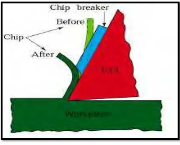
2.6 Chips Formations 19
2.7 Selection the cutting tools 20
2.7.1 Basic Insert Shape and Size 21
2.7.2 Chip Breaker Design 22
2.8 Cutting Tool Materials 22
2.9 Aluminium Alloy 23
2.10 Cutting Fluids 25
2.10.1 Purpose of Cutting Fluids 26
2.12 Tool Wears and Tool Life 26
CHAPTER 3: METHODOLOGY 30
3.1 Flow chart 31
3.2 Material Selection 32
3.3 Machine and Equipment 34
3.3.1 Conventional Lathe Machine 34
3.3.2 Horizontal Bandsaws 35
3.3.3 Stereo Microscopes 36
3.3.4 Electron Scanning Microscopes 37
3.4 Experiment method 38
3.4.1 Experimental set-up 38
3.4.2 Process Parameter 38
3.4.3 Steps in turning operation 39
3.5 Analysis on Cutting Tool 43
CHAPTER 4: RESULT & DISCUSSION 44
4.1 Introduction 44
4.2 Result Analysis 45
4.3 Wear Mechanism 56
vii
4.3.2 Crater Wear 58
4.3.3 Built Up Edge 59
4.3.4 Chip Formation 60
4.3.5 Wear Mechanism of Aluminium Alloy 61
CHAPTER 4: RESULT & DISCUSSION 63
5.1 Conclusion 63
5.2 Recommendation 64
REFERENCES 65
APPENDICES
viii
LIST OF TABLES
2.1 Factor influencing machining operations 7
2.2 Manufacturing properties and typical applications of selected wrought
Aluminium Alloys 24
2.3 Chemical Position of Aluminium 2024 25
3.1 Information about carbide insert 34
3.2 Aluminium alloy properties 34
3.3 General Information of Lathe Machine 36
3.4 General Information of Horizontal Bandsaw 37
3.4 General information of Stereo Microscopes 37
3.6 General Information of SEM 38
3.7 Experiment Parameters 40
4.1 Data for dry condition 46
ix
2.7 General Recommendations for Tool Angles in Turning 15
2.8 Summary of turning parameter and formulas 16
2.9 Depth of cut calculation 18
2.10 Method of mounting inserts on tool holders 21 2.11 Difference shape with increasing strength and chipping 21
x 3.14 Stop watch used to measure the amount of time in turning operation 43
4.1 Flank wear vs. cutting speed for dry cutting condition 46 4.2 Flank wear vs. cutting speed for the wet cutting condition 47 4.3 Comparison between wet and dry cutting condition 48
4.4 Flank wear on dry Condition (m/min) 49
4.5 Flank wear on wet Condition (m/min) 50
4.6 Crater wear on dry cutting Condition (m/min) 51 4.7 Crater wear on wet cutting Condition (m/min) 52 4.8 Development BUE at cutting tool on dry condition (m/min) 53 4.9 Development BUE at cutting tool on wet condition (m/min) 54 4.10 Formation of chip on dry cutting at various speeds (m/min) 55 4.11 Formation of chip on wet cutting at various speeds (m/min) 56 4.12 Effect of cutting speed on the flank wear for both cutting conditions 58 4.13 Effect of cutting speed on the mode of tool wear for dry and wet cutting
condition 59
xi
LIST OF ABBREVIATIONS
Al – Aluminium
BUE - Built up Edge
DOC - Depth of Cut
DOE - Design of Experiment HSS - High Speed Steel SM - Strereo Microscopes
1
CHAPTER 1
INTRODUCTION
The introduction elaborates the main idea of the project, whereas it introduces the title, the project background, objectives, problem statement and scope of the project. The specification of the study is enlightening in this chapter as guidance and information about this project.
1.1 Background of Research
2
For that reason, study of tool wear is an important in order to find suitable parameter for machining aluminium alloy because of the factor that affects productivity and manufacturing efficiency. In response tool wear of carbide cutting tool are being subject of interest to study their behaviour when machining on aluminium alloy under dry and wet condition. However, research has consistently shown that tool wear are the consequence of the load, friction, and high temperature between the edge of cutting and the work piece. The major causes of tool wear are mechanical, thermal, chemical, and abrasion. The cyclic mechanical forces cause fatigue on the tool cutting edge. The temperature of a tool increases as the cutting speed increases (Gu et al, 1999).
3
This project investigates tool wear of carbide cutting tools when machining aluminium alloy on wet and dry condition at different cutting speed. In this research, the evaluation of machining performance of the cutting tools mentioned above depends on the tool wear and wear mechanism. The methodology used in this project is experimental procedures. By referring to an experiment that will be done, the tools must undergo a machining test at various cutting condition before analysis is done with the tool. The evaluation of this research will be examined using a stereo microscope (SM) and scanning electron microscopes (SEM)
1.2 Problem Statement
In industry, machining operation such as turning, milling, drilling and grinding commonly use especially in the manufacturing industry. There needs to produce high volumes of product in order to ensure their company always achieves their target. The optimization of machining processes for the achievement of high responsiveness of production. However, it can cause wear on the cutting tool. Which it a result of physical contact between cutting tool and workpiece that remove small parts of the material from the cutting tool. Tool wear can cause catastrophic failure of the tool that causes significant damage to the workpiece and even to machine tool after a certain limit.
4
1.3 Objective
(a) To identify the effect of cutting speeds on tool wear of the carbide cutting tools during machining aluminium alloy at dry and wet conditions.
(b) To analyse the type of wear mechanisms during machining aluminium alloy at dry and wet conditions
(c) To compare the performance of tool wear under dry and wet machining.
1.4 Scope of Research
5
CHAPTER 2
LITERATURE REVIEW
The literature review is one of the scope studies which is locating and summarizing the studies about a topic. It will provide part in order to get the whole data about lathe machine, cutting tools and workpiece material and will give an idea to run the project. This chapter presents related study done by previous research on the tool wear, tool life and surface roughness. The purpose of this chapter is to gather the information that could contribute to this project.
2.1 Metal Machining
6 2.1.1 Machining Element
According to Kalpakjian and Schmid (2009), there are several primary elements in the following below that are required for a machining process.
(a) Workpiece: Its shape and size for continuous and intermittent cutting, the chemical composition, mechanical properties and metallurgical properties.
(b) Tool: Material and geometry
(c) Chip: Types of chips and their geometry
(d) Cutting fluid: Its chemical composition, rate of flow and the mode of application.
Figure 2.1: Machining by cutting (Kalpakjian and Schmid, 2009)
2.2 Mechanic of Cutting
7
Table 2.1: Factor influencing machining operations (Kalpakjian and Schmid, 2009)
Parameter Influence and interrelationship
Cutting speed, depth of cut, feed and cutting fluid.
Forces, power, temperature rise, tool life, type of chip, surface finish and integrity.
Tool angles As above, influence on chip flow direction, resistance to tool wear and chipping. Continuous chip Good surface finish, steady cutting force,
undesirable, especially in automated machinery. Built up edge chip Poor surface finish and integrity; if thin and stable,
edge can protect tool surfaces.
Discontinuous chip Desirable for ease of chip disposal; fluctuating cutting forces; can affect surface finish and cause vibration and chatter.
Temperature rise Influences tool life, particularly crater wear and dimensional accuracy of work piece; may cause thermal damage to work piece surface.
Tool wear Influences surface finish and integrity,
dimensional accuracy, temperature rise, forces and power.
Machinability Related to tool life, surface finish, forces and
2.3 Lathe Machine
8
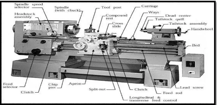
Figure 2.2: Lathe Machine (Kalpakjian and Schmid, 2009)
2.3.1 Lathe Components
Lathes are equipped with a variety of components and accessories such as bed, carriage, headstock, and tailstock as shown in figure 2.3.
Figure 2.3: Component of lathe machine
9
(a) Bed
Bed is the base of lathe machine because it supports all major components in the lathe. The bed is built rigid and made from grey or nodular cast iron. The main features of beds construction are the ways in which formed at the top portion besides run the full length of the bed.
(b) Headstock
The headstock is permanent to the bed and it equipped with motors, pulley, and belts. It rotates the work by using a chuck. It driven by an electric motor connected either to a belt or pulley system or to a geared system. The speed can be set manually through controlled selector or by electrical control. For long bars or tubing workpiece, holding device such as chuck and collets is used with headstock for various turning operations.
(c) Tailstock
The tailstock is placed at the opposite end of the lathe from the headstock. Tailstock can be clamped in any position and can slide along the ways and support the other end of the workpiece. It has two types of centre which fixed centre or live centre.
(d) Carriage