________________________________________
: Corresponding Author
The 11th Asia Pacific Industrial Engineering and Management Systems Conference
The 14th Asia Pacific Regional Meeting of International Foundation for Production Research
Melaka, 7 – 10 December 2010
Development of a Solar Car
Zahari Taha1
Faculty of Manufacturing Engineering and Technology Management Universiti Malaysia Pahang
26300 Kuantan, Pahang. Malaysia E-mail: [email protected]
Rossi Passarella 2 , Nasrudin Abd Rahim3 and Aznijar Ahmad-Yazid4 2,4
CPDM and 3UMPEDAC
Faculty of Engineering, University of Malaya 50603, Kuala Lumpur, Malaysia E-mail: [email protected]
E-mail : [email protected] E-mail : [email protected]
2
Faculty of Computer Science, UniversitasSriwijaya, Palembang, Indonesia
Jamali Md Sah4
School of Manufacturing Engineering Universiti Malaysia Perlis 02600,Arau, Perlis, Malaysia Email: [email protected]
Abstract- Solar car can be categorized as a ‘green vehicle’ which is powered by renewable energy with zero carbon
emission. Various numbers of solar race events organized around the world has propelled the continuous development of solar cars by different research teams. These events have become the platform for universities and private companies to showcase their latest technologies and findings in utilising solar energy to drive their vehicles. Solar car development cost has been observed to increase significantly over the years with most teams having the sole aim of winning the race at all costs, instead of producing a practical solar car suitable for everyday use. Bucking this trend, Centre for Product Design and Manufacturing has recently developed a solar car using off-the-shelf components in order to reduce the development cost. It presented a big challenge to the team in combining those components while aspiring to achieve optimum operating conditions.
This paper describes the design concept of this ‘alternative’ solar car, the mechanical, electrical and telemetry systems and
some performance characteristics of the car. During the recently concluded World Solar Challenge 2009, even though the developed solar car has managed to cover only 20 percent of the total distance required but managing to received positive responses due to its practicality, novel concept and comfort factors.
Keywords: Solar car, off-the-shelf components, design concept, world solar challenge.
1. INTRODUCTION
Interest in green vehicles has grown in recent times due to their pollution-free characteristics, with everyone wanting to jump into the ecological-friendly alternative mode of transport. One type of green vehicles which is very popular is the solar-powered vehicle. Solar cars have the solar energy tapped using rows of solar panels, charging
batteries and used to power the electric motor of the vehicle. There are a number of solar car race events organized by lots of different countries such as Australia, the United States of America, Japan and South Africa. These events are used as a platform for researchers, educational institutions and automotive corporations to develop environmental friendly vehicle for future use.
The 11th Asia Pacific Industrial Engineering and Management Systems Conference
The 14th Asia Pacific Regional Meeting of International Foundation for Production Research
Melaka, 7 – 10 December 2010
participating in those events for the last 20 years has been so remarkable in terms of the materials, mechanical and electrical components used, and the energy management systems employed had resulted to the introduction of few high-speed aerodynamic solar cars which are capable of reaching a top speed of 120 km/h. However, those advanced technologies require millions of dollars in investment. This fact was proven at the recently concluded World Solar Challenge (WSC) in Australia where several solar cars cost more than USD 1 million. At the moment, mass production of solar cars for commercial use is not possible unless researchers start to develop an economical solar car that is highly reliable and able to meet the demand for everyday use.
2. THE WORLD SOLAR CHALLENGE
In 1982, the world’s first solar car was driven across
Australia by Hans Tholstrup, a Danish adventurer, from Perth to Sydney, in 20 days. His passion in motor sport and the average speed of 105 km/h, with a maximum recorded speed of more than 140 km/h. Technological development of solar car participating in the WSC for the last 20 years has seen the average speed rising tremendously aerodynamic shape and vehicle weight are the two most important factors influencing
a solar car’s speed and much advancement has been made in
these two areas. Materials used to build solar cars have changed and evolved dramatically since the first event. Composite materials used in aerospace industries are used frequently these days. These aerospace materials are lightweight, yet strong. The shape and appearance of solar cars has altered quite dramatically as aerodynamic factor becomes a very strong influencing factor. Different vehicle shapes were experimented with in the early days, before the
‘cockroach’ shape was accepted as being the best to achieve
optimum speed and aerodynamics characteristics. The WSC 1993 had seen 3 solar car teams employing the wheel motor for the first time out of 52 participating teams. At this juncture, tyre manufacturers also began to take interest in constructing tyres of low rolling resistance, especially-designed for WSC events (Taha et. al. 2008; The world solar challenges, 2010)
To further reduce weight, battery technology development was given special consideration. In the early days, silver zinc batteries were used, which were expensive and heavy. The higher energy density of batteries used today especially the lithium ion batteries, have made them
significantly lighter compared to the lead acid batteries. Other component that has developed significantly is the solar cell technology. The fast solar cars have solar cells capable of harvesting the highest amount of energy from the solar panels. The most successful solar vehicle which has won 4 WSCs,
‘Nuna’ from Delft University of Technology, Netherlands,
had utilised ‘maximum power point trackers’ (MPPT) mechanism. These MPPTs are normally used by satellites to optimise the output of solar cells even when they are in the shade. A chip in the MPPT continuously measures the voltage supplied by the solar cells, compares it with the fixed battery voltage, and then determines the best voltage to charge the experimental devices to sophisticated electronic gearboxes with no moving parts and has become an essential component of the emerging hybrid and electric cars. Energy from the Sun
is captured by the cells of the car’s solar array, which
produces an electrical current. The current can be routed either to the batteries for storage or to the motor controller directly, or a combination of both. The energy sent to the controller is used to power the motor that turns the wheel and moves the car. Whenever the car is in motion, the converted energy from the sun is generally delivered directly to the motor controller, but there are times when the energy from the array is greater than the requirement of the motor. When this happens, the extra energy is relayed to the batteries for later use. However, there are instances when the energy produced by the solar array is un-sufficient to drive the motor at the desired speed; the array's energy is supplemented with stored energy from the charged batteries.
As the solar cars technology progresses during the recent years, to ensure solar cars edging closer towards practicality and becoming greater user-friendly, the organizer of the WSC event keeps introducing new regulations. The
solar cars participating in the event need to have ‘normal
-car-like’ features such as more upright seating, unaided driver access and exit, with indicator lights at front and rear of the vehicle and is also equip with a reverse gear. Solar array area on vehicles has also been cut by 25 per cent, from previously at 8 m2 to 6 m2. The organizer are confident that there are still a lot more development can be introduced in solar car technology and eventually, solar car will be ready for every-day use.
3. UNIVERSITY OF MALAYA SOLAR CAR
3.1Merdeka 1
The 11th Asia Pacific Industrial Engineering and Management Systems Conference
The 14th Asia Pacific Regional Meeting of International Foundation for Production Research
Melaka, 7 – 10 December 2010
consist of 12 members has been set-up in January 2007 and the first project activity was to develop the design of the solar car. Because of the limited fund and time to fabricate the solar car, the team has decided to use the common parts and components available off-the-shelf as the team was trying to keep the cost of the solar car as minimum as possible. These components include the solar or photovoltaic (PV) panels, batteries, motor and most of mechanical parts such as the braking system and wheels. Therefore, the design of the first solar car which was named Merdeka 1 was very much dependent on the shape and size of the solar panels. The main body structure was fabricated using hollow steel rod and fibre glass sheet was used to cover most of the lower part of the vehicle. The solar car used PV panels which are designed and fabricated for roof application with a glass sheet covers the solar cells and placed in an aluminium frame. The valve-regulated lead-acid gel type batteries were chosen for the solar car mainly because of the charging characteristics and also it was much cheaper compare to lithium ions batteries.
Figure 1. CPDM’s Merdeka 1Solar car
The car was driven by a 48V direct current (DC) motor which was originally used in mountain bikes. Due to the characteristics of the DC motor which has low torque, a gear box was directly connected to the motor in order to prevent the occurrence of high current in the motor controller and a motorcycle chain was used to link the gear box with the single rear motorcycle wheel.Other parts used such as the steering, front wheels, suspension and braking systems are standard parts as use in motorcycle and car. There are some disadvantages of using these off-the-shelf components especially when using the solar panels for the solar vehicle since they resulted to more weight of the car and consequently the current consumption to power the vehicle was much higher than the current charging rate from the panels. In the WSC 2007, the solar car had only managed to complete approximately 320 km of the total 3000 km distance with the average speed of 30 km/h. The main problem was due to the design of the stand alone power management system which was unable to balance
the power consumption required to run the vehicle with the power generated from the PV during the race time.
3.2Merdeka 2
In 2009, CPDM had participated again in the WSC with a second version of solar car which was named Merdeka 2 as shown in Figure 2. The concept of using off-the-shelf components was maintained and it was designed to be as close possible as a normal car with the solar panels were placed on top to function as the roof of the car. The vehicle main body structure was fabricated using 38 mm aluminium hollow pipe of 3.14 mm thickness. Other components used such as the wheels, spring suspensions, steering and seat are all off-the-shelf parts. The solar car used a 48V permanent magnet DC motor of 3000 maximum r.p.m. and there were 4 units of 12V deep cycle batteries to store the electrical energy from the solar panels and powered the motor. In this car, there were also 4 units of Maximum Power Point Tracking (MPPT) acting as the PV charging controller. Each MPPT was connected to each panel and to charge each of the 12V battery. In the event with the average speed of 45 km/h, the solar car had managed to finish 590 km of the total race distance which is approximately 100% improvement compared to previous solar car. Again, it is going to be a huge task for researchers at CPDM to continue with the development of solar car in the future with the aim of completing the race with the limitation on the funding.
Figure 2. CPDM’s merdeka 2 solar car
4. ELECTRICAL SYSTEM FOR MERDEKA 2
The 11th Asia Pacific Industrial Engineering and Management Systems Conference
The 14th Asia Pacific Regional Meeting of International Foundation for Production Research
Melaka, 7 – 10 December 2010
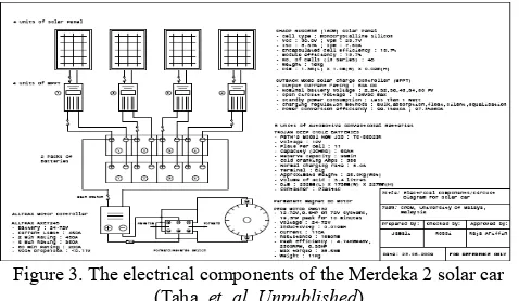
cells is covered by a sheet of glass and hold by 1.3 x 1.0 m aluminium rectangular frame. There were 4 panels used for the vehicle and each panel has its own Outback MX80 MPPT to maximise the charging current from the panels into the deep cycle 12V Trojan batteries. This subsystem which consisted of the panels, batteries and the MPPTs was also called Small Generator Module (SGM) as proposed by Taha et. al. 2010a, which is shown in Figure 3.
This combination of the components was able to produce a maximum current of 14A. The 4 SGMs on the vehicle were combined to maximise the current stored into the batteries which resulted to a maximum power of 2.7 kW. The battery pack produces 48V with a capacity of 105Ah. The motor controller takes 48V DC current from the batteries and supplies it to the motor. An accelerator which is hooked to a potentiometer provides a signal to the controller and indicates the amount of current it is supposed to deliver. The controller will supply the current from zero to maximum according to the position of the accelerator or the potentiometer. This current from the controller is used by the motor to move the solar car. This PMG 132 motor, a brushed permanent magnet and pancake type DC motor is manufactured by Perm Motor, Germany. It is designed to
Figure 3. The electrical components of the Merdeka 2 solar car
(Taha, et. al, Unpublished)
This system setting has able to maintain a current of 20A when the vehicle is moving at 45 km/h on a flat road. This value is lower than the maximum charging capacity of 56A from the total of 4 SGMs. During the race however, the average current consumption recorded was approximately 80A which was higher than charging capacity. The main reason for this high consumption was due to the slope of the road which at some points the current consumption exceeded 100A. As a result, it was impossible to drive the solar car continuously during the 8 hours race day due to this charging capacity, adding that the solar panels were unable to always produce maximum current as there were clouds at some areas.
5. DESIGN CONCEPT AND STRUCTURE OF MERDEKA 2
Several factors must be considered when designing the solar car as the process involves multidisciplinary fields. At the early stage, the design work requires a balance consideration and compromise between four fundamental demands, namely the product cost, design cost, product performance and design time. The material selection process however, depends on several aspects either it is design-oriented, product oriented, cost oriented or environment oriented as noticed by Taha et. al. 2009a. These demands and material selection requirements had influenced the design team at CPDM to apply the sustainable product concept for Merdeka 2. The development activity for the solar car can be considered as a one-off project. It can be said that the design concept for the vehicle is very much dependent on the investment. Since cost is the main concern for this project, the ability to recycle and re-use the materials and parts that have been used for the vehicle is very important. The conceptual design of the solar vehicle was very much dependent on the dimension and profile of the electrical and mechanical components that were used. The top area of the vehicle was designed to accommodate the 4 solar panels. The chassis was designed to cater the load and to accommodate all the electrical and mechanical components with considerations of simplicity, lightweight and easy maintenance. Generally, the structure of the Merdeka 2 can be divided into 6 important groups namely the car body, steering system, the wheels, braking system, suspension and also the driver compartment.
The 11th Asia Pacific Industrial Engineering and Management Systems Conference
The 14th Asia Pacific Regional Meeting of International Foundation for Production Research
Melaka, 7 – 10 December 2010
Figure 4. The structural design of merdeka 2 6. TELEMETRY SYSTEM
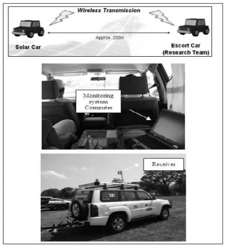
In WSC 2009, the monitoring system has to acquire data from the sensors and send out the data through wireless connection as reported by Taha. et al 2010b. At the same time the system will saved the data into controller and laptop for analysis purposes as shown in Figure 11. A data acquisition and telemetry system (DAQ-T) is developed to fulfill the needs of the research team where LabVIEW was used as a programming language for the DAQ-T. Development of DAQ-T required 5 important components which are the programming software, National Instruments (NI) LabVIEW, the controller, NI CompactRIO (C-RIO) and Xstream OEM Radio Frequency Modules.
Figure 11. Data acquisition and telemetry system of
Merdeka 2 solar car (Taha. et al, 2010b).
Laboratory Virtual Instrumentation Engineering Workbench or LabVIEW is a graphical programming language for instrument control and data acquisition, analysis and presentation. In DAQ-T, LabVIEW is used to program the controller C-RIO. C-RIO is a programmable automation controller. It is an advanced embedded control
and data acquisition system designed for applications that require high performance and reliability. It is small, light weight, rugged, low power consumption and flexible. It needs to program with LabVIEW to deliver a powerful real time (RT) signal acquisition, analysis, control and data logging (Taha. et al 2009b). This controller is very suitable to be applied in solar vehicle as a DAQ-T during WSC 2009 as it can withstand and perform in the harsh competition environment at the same time consuming low power. C-RIO consists of three major components namely the embedded real-time processor, high performance Field Programmable Gate Array (FPGA) chassis and hot-swappable input-output (I/O) modules. Maxstream Xstream is a radio frequency (RF) module with outdoor out of sight range of 11 km. It provides communication link between the solar vehicle and the escort team. It is commonly applied for remote application.
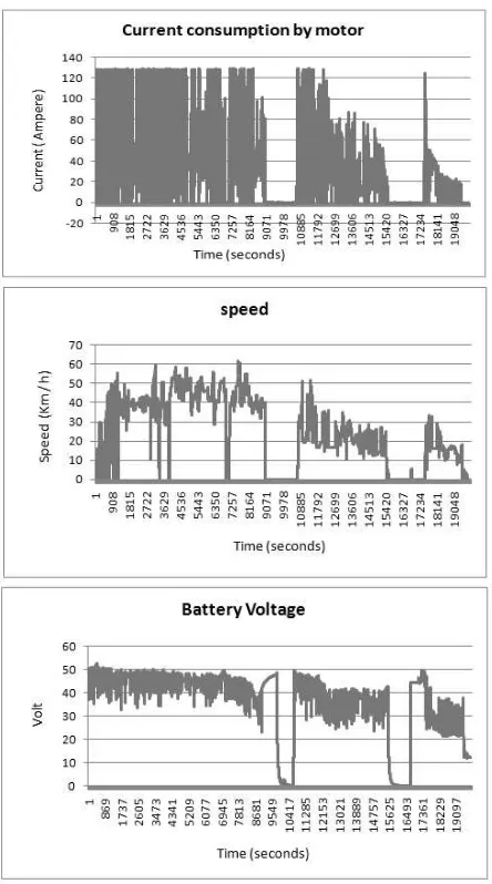
During WSC 2009, there were 4 data required from the 6 units of thermocouples, 2 units of current transducers, 1 group of batteries and 1 unit of tachometer. Therefore, there were 4 input modules selected in total. Each of the NI 9211 input module consist of 4 channels. Total of 2 unit of NI 9211 were used to accommodate 6 units of thermocouples. 2 units of thermocouples were placed on the PV cells, 2 units of thermocouples measured the temperature of motor and the other 2 units on the batteries. An NI 9221 8 channels +- 60 V input module was needed to measure the voltage level of a group of battery pack and to obtain the signals of 2 units of current transducers which measured the current of the motor. An NI 9215 8 channels input module was used to measure the signals from the tachometer. Each of the sensors was connected to the respective I/O module which was fixed on the FPGA chassis of the C-RIO. The real time controller processed and sent the data to computer through the transmitter of Xstream RF module for monitoring. The data measured (Figure 12) was saved into C-RIO and the laptop as the visual display of program shown in Figure 13.
The 11th Asia Pacific Industrial Engineering and Management Systems Conference
The 14th Asia Pacific Regional Meeting of International Foundation for Production Research
Melaka, 7 – 10 December 2010
Figure 12. Example data collected by DaqT in WSC 2009 from merdeka 2, consists of speed, voltage, current charging, and
current consumption (Taha et al.Unpublished)
Figure 13. Visual Display of the Program using Lab View (Taha et
al 2009b).
7. CONCLUSION
The development process of a solar car is not an easy tasks especially it requires a lot of efforts and time from the team members and most importantly the investment is high. However, those factors will not prevent the CPDM solar car team from continuing their efforts to design and build more solar cars in order to achieve the goal of finishing the race in the coming WSC events. There are number of challenges and obstacles before the dream solar car can be fabricated but with the experiences and knowledge obtained from the previous WSC events, the dream will come true.
References
The world solar challenges, Cited on 2010 June 11
available from: http://www.anzses.org/files/The% 20WORLD %20Solar%20Challenge.pdf
Zahari Taha, Rossi Passarella, Jamali Md Sah and Nasrudin Bin Abd Rahim (2008). A Review on Energy Management System of a Solar Car, The 9th Asia Pacific Industrial Engineering & Management Systems Conference,3-5 December 2008, Nusa Dua, Bali, paper 93, pp. 2527-2530.
Zahari Taha, Rossi Passarella, Nasrudin Abd Rahim, Jamali Md Sah (2010a). Driving force characteristic and power consumption of 4.7 kW permanent magnet motor for a solar vehicle, ARPN Journal of engineering and applied sciences, vol 5, No 1 January 2010, ISSN 1819-6608
Z. Taha, J.M. Sah, R. Passarella, R.A.R. Ghazilla, N. Ahmad, Y.H. Jen, T.T. Khai, Z. Kassim, I. Hasanuddin, and M. Yunus (2009a). A Solar Vehicle based on Sustainable Design Concept, The IASTED International conference on Solar Energy ~SOE 2009~ ISBN: 978-0-88986-791-8 Phuket, Thailand 2009
Z. Taha, R.Passarella, H.X.How, J.Md.Sah, N. Ahmad, R.A.R. Ghazilla, H.J.Yap (2010b), Application of data acquisition and telemetry system into a solar vehicle. The 2nd International Conference on Computer Engineering and Applications (ICCEA 2010),
Z. Taha, R. Passarella, J.M. Sah, H.X. Hui, N. Ahmad, R.A.R.Ghazilla, Y.H. Jen, and T.T. Khai,(2009b) Developing of Telemetry Monitoring system for a Solar Vehicle, Proceeding of the IASTED international Conference on Solar Energy, 16-18 March 2009, Phuket, 647-035.pp 44-50.