CONSTRUCTION OF A SYSTEM FOR DEFINING AREAS WHICH ARE NOT
OBTAINED DATA FROM STEREO IMAGES
Hideharu Yanagi a, c, Hirofumi Chikatsu b
a
Japan Association of Surveyors, 1-48-12, Itabashi, Itabashi-ku, Tokyo 173-0004, Japan - [email protected] b Department of Civil and Environmental Engineering, Tokyo Denki University,
Hatoyama, Hiki-gun, Saitama 350-0394, Japan - [email protected] c
School of Science and Engineering, Tokyo Denki University, Hatoyama, Hiki-gun, Saitama 350-0394, Japan
Commission V, WG V/1
KEY WORDS: Macro lens, Digital very close range photogrammetry, 3D modeling, Small object
ABSTRACT:
Recently, digital documentation and visualization of various cultural assets have been receiving attention. For example, a small Buddha with a height of approximately 4 cm is categorized as a cultural asset. Such a small object has to be documented.
Generally, in order to perform 3D modeling of small objects from the viewpoint of digital very close range photogrammetry, multi view images are taken. However, it is important to confirm the occluded part and image quality after taking images.
In order to confirm the defocusing of images and the areas which were not obtained data from stereo images, a system is proposed for confirming data with a macro lens and convenient 3D measurement software called 3DiVision. Finally, it is proposed that the data be supplemented in areas which are not obtained data.
1. INTRODUCTION
Recently, digital documentation of various cultural assets has been receiving attention. Small objects, such as an extremely small Buddha with a size of approximately 4 cm and an old coin that was unearthed from remains, are categorized as cultural assets. In order to document such small cultural assets, convenient 3D measurements are required.
On the other hand, convenient 3D measurements using consumer-grade digital cameras are eagerly awaited in various application fields. In these circumstances, the desire is not only for convenient 3D measurements using consumer-grade digital cameras but also for a convenient method to integrate multiple images without ground control points (GCPs). The authors have been attempting to develop convenient 3D measurement software called 3DiVision by using consumer-grade digital cameras (Chikatsu et al., 2006). 3DiVision has the capability to perform exterior and interior orientation simultaneously without GCPs.
Generally, in order to perform 3D modeling of a small object, multi view images are taken by digital very close range photogrammetry. However, it is important to confirm the occluded part after taking images. In 3D measurements using a terrestrial laser scanner, a problem due to occlusion has reportedly been solved by inserting a two-dimensional high resolution image into the missing location in the 3D model (Martínez et al., 2011). In digital very close range photogrammetry, the construction of an imaging system to confirm data in real time is needed in order to confirm as soon as possible the defocusing of images and the areas which were not obtained data from stereo image.
With this motivation, an imaging system with 3DiVision and a macro lens was proposed in the present study. Moreover, an investigation was conducted on the proposed method for supplementing the data in areas which were not obtained data from stereo images.
2. PROPOSED IMAGING SYSTEM
Table 1 lists the specifications of the macro lens that was used in this investigation. This lens was mounted on a Canon EOS 50D.
In order to construct the proposed imaging system, the following are required:
1) Consider the working distance from the small object to the camera.
2) Take multi view images using one camera. 3) Construct a pseudo 3D model in real time. 4) Confirm the defocusing of images.
5) Make convenient 3D measurements using consumer grade digital cameras without GCPs.
6) Define the areas which were not obtained data from stereo images.
7) Supplement the data in areas which were not obtained data from stereo images.
The imaging system proposed in this study and that satisfies requirements 1 through 6 is shown in Figure 1. The size of the small object shown in Figure 1 is approximately 8.6 cm and the altitude is approximately 90 cm. The camera is connected directly to a personal computer (PC), and images are taken using the PC.
Camera
Canon EOS 50D 15.1 megapixels, CMOS Sensor size: 22.3 × 14.9 mm
Lens Canon EF100mm f/2.8 Macro USM Focal length: 100 mm, F: 2.8
Table 1. Specifications of camera and lens International Archives of the Photogrammetry, Remote Sensing and Spatial Information Sciences, Volume XXXIX-B5, 2012
Figure 2. Pseudo 3D model. The depth of field depends on the principal distance and the
aperture value of the lens. For 3D modeling of cultural assets in particular, it is important to adjust the depth of field for each image obtained. However, appropriate imaging modes can be used to achieve superior imaging. The camera listed in Table 1 offers a selection of imaging modes as follows:
• P mode (program automatic exposure):
Aperture value and shutter speed are set automatically depending on the brightness.
• AV mode (aperture value):
Aperture value can be changed manually.
• A-DEP mode (automatic depth of field):
Aperture value is set automatically depending on the auto focus (AF) frame.
In this study, the AV mode was selected for the ability to set an aperture value manually with respect to the depth of field. The focal length of the macro lens specified in Table 1 is fixed. Another characteristic feature of a macro lens is the working distance; i.e., the distance between the front of the lens and the object. Suitably adjusting the working distance enables the capture of sharp images without the influence of shadows caused by lighting.
As shown in Figure 1, it is understood that requirements 1 and 2 are satisfied because the camera position is fixed and a turntable is used. Requirements 3 through 6 will be discussed in the sections below.
3. THE PSEUDO 3D MODEL
A characteristic of the proposed system is a fixed camera position. The small object is set at the center of a turntable. The turntable is rotated in one direction, and images of the small object are taken with one camera. Therefore, the small object is always in the center of the image. In addition, the images of the small object are saved in a PC, because the camera is connected directly to a PC. The images of the small object are taken by the PC while the turntable is rotated in one direction. After the turntable has rotated once, the images of the small object appear continuous like a 3D model rotated on a display. In this study, the continuous images that are shown in Figure 2 are called the pseudo 3D model.
Therefore, the image defocusing and the occlusion areas are confirmed from the pseudo 3D model. Thus, it is understood that requirements 3 and 4 are satisfied.
4. 3D MODELING AND ORTHOPHOTOS
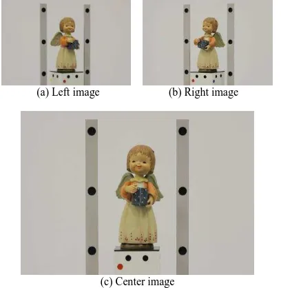
The proposed imaging system uses 3DiVision. Hence, it is understood that requirement 5 is satisfied. In this study, triplet images that are taken using the proposed imaging system (Figure 3) and 3DiVision are used for 3D models and orthophotos.
(a) Left image (b) Right image
(c) Center image
Figure 3. Triplet images. Figure 1. Proposed imaging system.
Altitude is constant.
Turntable
Rotates in one direction.
(a) Original image (b) Image processed using a Wallis filter
Figure 4. Image processed using a Wallis filter.
(a) Original image (b) Classified image
Figure 5. Image processed using an Otsu method.
4.1 Image processing
In this study, the feature points for the 3D modeling of the small object were obtained by stereo matching the left and right images of the triplet. However, it was difficult to obtain the feature points of the small object because there are many similar colors and patterns on its surface. Therefore, the feature points were increased by processing the images using a Wallis filter (Jazayeri & Fraser, 2008). The Wallis filter enhances the contrast of an image. Figure 4 shows an image processed by using the Wallis filter in equation (1) with a mask size of 51 × 51. The parameter values applied to the Wallis filter were as
sg: Original standard deviation mf: Target mean
Sf: Target standard deviation c: Contrast expansion constant
b: Brightness forcing constant
4.2 Stereo matching
Generally, it seemed that the stereo matching needed much processing time. Therefore, in order to reduce the processing time, the image was divided into areas (Figure 5) by using an Otsu method (Otsu, 1980), and the stereo matching process was done in each area without a background.
However, mismatching is an extremely important issue in stereo matching. In this study, in order to reduce the amount of mismatching, a reverse projection method (Sugiyama & Chikatsu, 2011) was used in the stereo matching process. The reverse projection method uses triplet images and each orientation element of the image. The reverse projection method is implemented as follows: first, the stereo matching is performed using the left and right images (Figure 3); second, the result point of the matching is checked with points on the center image that were projected using the interior and exterior orientation elements of the center image. In this study, the stereo matching method uses the area-based matching that is given by equation (2). The correlation value threshold and masking window size were set to 0.4 and 51 × 51, respectively.
m:Height of masking window
l: Width of masking window
f(u, v): Threshold of pixel position (u, v) in the target image
t(u, v): Threshold of pixel position (u, v) in the template image
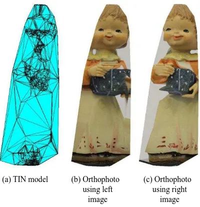
4.3 TIN modeling and orthophoto images
Figure 6(a) shows a triangulated irregular network (TIN) model using result points described in Section 4.2. Figures 6(b) and 6(c) show the orthophoto images obtained using the TIN with the left and right images, respectively. From these results, it is clear that each orthophoto image is a stretched texture image with textures other than those of the doll.
(1)
(2)
Figure 6. TIN model and orthophoto images.
(a) TIN model (b) Orthophoto
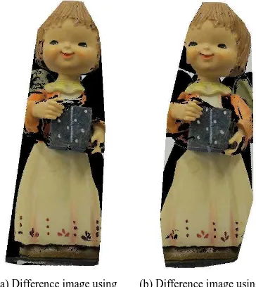
Figure 8. Difference image.
(a) Left image (b) Right image
Figure 7. Difference in color information.
4.4 Defining areas which are not obtained data from stereo images
Each orthophoto image is constructed from corresponding points on left and right images that have been extracted by stereo matching. Therefore, it seems that the texture images of the orthophoto images should each contain the same color information. However, Figure 7 shows that the texture images extracted from the left and right images are different. It is clear in Figure 7 that the color information within the red triangles is the same but the color information within the blue triangles is not.
With this motivation, a difference image was constructed using Figures 6(b) and 6(c). Figure 8 shows the difference image that is extracted given the same color information at the same location in both images. The black areas shown in Figure 8 are the areas where the same color information cannot be extracted from both images (e.g., anywhere that color information recorded in the left image was not recorded at the same location in the right image). From these results, it is clear that the black areas in Figure 8 define areas which are not obtained data from stereo imagea.
5. DEFINING AREAS WHICH ARE NOT OBTAINED DATA FROM TRIPLET IMAGES
The triplet image is used in this proposed system. In Section 4.4, the left and right images are used for defining areas that are not
obtained data. Therefore, it can be inferred that additional data can be obtained from the pair of left and center images or the pair of center and right images. Figure 9 shows the difference image made from each pair. It is clear from this figure that different data were obtained in each image.
However, the images shown in Figures 8 and 9 were calibrated using the same coordinate system. Therefore, all three images can be overlaid. Figure 10 shows the three images overlaid, and data have clearly been added to the black areas in Figure 8. However, there are still black areas in Figure 10. That is, the black areas in Figure 10 show the areas which are not obtained data from images.
Consequently, it is understood that requirement 6 of Section 2 is satisfied.
Figure 10. Areas which are not obtained data from the triplet images.
Figure 9. Difference images.
(a) Difference image using left and center images
(b) Difference image using center and right images
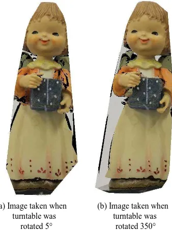
(a) Image taken when turntable was rotated 5°
(b) Image taken when turntable was rotated 350°
Figure 13. Images searched.
6. SEARCH FOR CORRESPONDING IMAGES
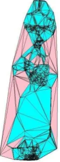
The orthophoto images constructed in this study are based on the TIN model. Therefore, in order to supplement the data in the areas which are not obtained data, the triangles forming the TIN are examined. The eye vector is a base vector that is defined between a triangle in the TIN and the camera position set in front of the small object. An image that corresponds to the area which is not obtained data is searched for by calculating the angle between the eye vector and normal vector of the triangle. Figure 11 shows the relationship between the eye vector and the normal vector. The angle between the eye vector and the normal vector is given by equation (3).
where, N: Normal vector
Q: Eye vector calculated using the pink triangles that are shown in Figure 12. The vector components correspond to each axis of the coordinate system shown in Figure 11 (e.g., a corresponds to the
X-axis). The vector components indicate the direction and magnitude corresponding to each axis. It is inferred that the angle represents the center image of the triplet.
In order to confirm that data can be supplemented, the angles and vector components were verified using the contents of Table 2 that are shaded in gray. These contents were selected because one angle (6.4359°) is near the top of the list. The other angle angle 2.5470° was same as that in Figure 3(c).
Figure 13 shows the images that were searched by the proposed imaging system. In this study, the turntable was rotated by increments of 5 degrees. Therefore, the search angle was selected close to the angles at which images were taken using this system.
As each image in Figure 13 is the center image of a triplet, the left and right images that corresponded to each center image were searched, and each difference image was constructed using the proposed method. Figure 14 shows the difference images that were constructed from these results.
Figure 11. Relationship between eye vector and normal vector.
Figure 12. Corresponding triangles (pink).
Eye vector
Table 2. Angle between eye vector and normal vector Angle(°) a b c International Archives of the Photogrammetry, Remote Sensing and Spatial Information Sciences, Volume XXXIX-B5, 2012
Figure 15 shows overlaid images of Figure 10 and Figure 14. In this figure, the black area in Figure 10 is supplemented using the image of Figure 14. Where the black areas are still not supplemented with data, it is possible to supplement using another angle in Table 2. Therefore, it is understood that requirement 7 of Section 2 is satisfied by this result.
From these results, all seven requirements that were described in Section 2 are satisfied.
7. CONCLUSION
In this study, the effectiveness and practicality of the proposed imaging system were investigated for the documentation of small objects. Consequently, results obtained in this study show that the proposed imaging system can be used effectively for the documentation of small objects, since the areas which are not obtained data are supplemented using the proposed method.
References
Martínez, J., Finat, J., Fuentes, L.M., Gonzalo, M., Viloria, A., 2005. A COARSE-TO-FINE CURVED APPROACH TO 3D
SURVEYING OF ORNAMENTAL ASPECTS AND
SCULPTURES IN FACADES. Proc. XX CIPA Symposium, Turin, 26 Sep. – 1 Oct.
http://cipa.icomos.org/ fileadmin/template/doc/TURIN/441.pdf (14 Apr. 2011).
Chikatsu, H., Ohdake, T., 2006. UBIQUITOUS DIGITAL PHOTOGRAMMETRY BY CONSUMER GRADE DIGITAL CAMERA. In: The International Archives of the Photogrammetry, Remote Sensing and Spatial Information Sciences, Vol. XXXVI, PART 5, ISSN 1682-1750 (on CD-ROM).
Jazayeri, I., Fraser, C.S., 2008. INTEREST OPERATORS IN CLOSE-RANGE OBJECT RECONSTRUCTION. In: The International Archives of the Photogrammetry, Remote Sensing and Spatial Information Sciences, Vol. XXXVII, PART B5, pp.69-74.
Otsu, N., 1980. An Automatic Threshold Selection Method Based on Discriminant and Least Squares Criteria. Trans.IECE of Japan, Vol. 63-D, No.4, pp.349-356.
Sugiyama, F., Chikatsu, H., 2011. Improvement in the Accuracy of DEM for Orthophoto Generation by Reverse Projection Method. Journal of JSPRS, Vol. 50, No. 2, pp.80-89.
(a) The image before (b) The supplemented supplementing data image
Figure 15. Supplemented difference image.
(a) Image taken when (b) Image taken when turntable was turntable was
rotated 5° rotated 350°
Figure 14. Difference images that were constructed using search angle.