IDENTIFYING SURFACE CHANGES ON HRSC IMAGES OF THE MARS SOUTH
POLAR RESIDUAL CAP (SPRC)
Alfiah Rizky Diana Putri, Panagiotis Sidiropoulos, Jan-Peter Muller
Imaging Group, Mullard Space Science Laboratory, Dept. of Space and Climate Physics, University College London, Holmbury St Mary, Surrey, RH5 6NT, UK - (alfiah.putri.15, p.sidiropoulos, j.muller)@ucl.ac.uk
Commission IV, WG IV/8
KEY WORDS: data mining, Mars south pole, HRSC, DTM, surface change, ice caps
ABSTRACT:
The surface of Mars has been an object of interest for planetary research since the launch of Mariner 4 in 1964. Since then different cameras such as the Viking Visual Imaging Subsystem (VIS), Mars Global Surveyor (MGS) Mars Orbiter Camera (MOC), and Mars Reconnaissance Orbiter (MRO) Context Camera (CTX) and High Resolution Imaging Science Experiment (HiRISE) have been imaging its surface at ever higher resolution. The High Resolution Stereo Camera (HRSC) on board of the European Space Agency (ESA) Mars Express, has been imaging the Martian surface, since 25th December 2003 until the present-day. HRSC has covered 100% of the surface of Mars, about 70% of the surface with panchromatic images at 10-20 m/pixel, and about 98% at better than 100 m/pixel (Neukum et. al., 2004), including the polar regions of Mars. The Mars polar regions have been studied intensively recently by analysing images taken by the Mars Express and MRO missions (Plaut et al., 2007).
The South Polar Residual Cap (SPRC) does not change very much in volume overall but there are numerous examples of dynamic phenomena associated with seasonal changes in the atmosphere. In particular, we can examine the time variation of layers of solid carbon dioxide and water ice with dust deposition (Bibring, 2004), spider-like channels (Piqueux et al., 2003) and so-called Swiss Cheese Terrain (Titus et al., 2004). Because of seasonal changes each Martian year, due to the sublimation and deposition of water and CO2 ice on the Martian south polar region, clearly identifiable surface changes occur in otherwise permanently icy region. In this research, good quality HRSC images of the Mars South Polar region are processed based on previous identification as the optimal coverage of clear surfaces (Campbell et al., 2015). HRSC images of the Martian South Pole are categorized in terms of quality, time, and location to find overlapping areas, processed into high quality Digital Terrain Models (DTMs) and Orthorectified Images (ORIs) and projected into polar stereographic projection using DLR (Deutsches Zentrum für Luft- und Raumfahrt; German Aerospace Center)’s VICAR and GIS software with modifications developed by Kim & Muller (2009). Surface changes are identified in the Mars SPRC region and analysed based on their appearance in the HRSC images.
1. INTRODUCTION
The HRSC (High Resolution Stereo Camera) on board of the ESA Mars Express spacecraft has been mapping Mars in stereo (3 views), polarisation (2 views) and four-band colour coverage since 25 December 2003, covering ≈98% Martian surface at 100 m/ pixel or better (Neukum, et. al., 2004). Its design make it possible to map topography of Mars, mapping it systematically with stereo coverage from which DTMs (Digital Terrain Models) and terrain-corrected orthorectified image (ORI) and DTM mosaics of the Martian surface. As HRSC has covered 98% of the Martian surface, the south polar region of Mars has also been covered by HRSC. HRSC has been taking images of Mars for more than 12 years, with multiple acquisitions taken over the same area (see Sidiropoulos and Muller, 2015b). The repeat HRSC images are particularly suited for change detection research of the Mars surface, especially if coregistered and combined with images from other cameras orbiting Mars (Sidiropoulos and Muller, 2015a). Its stereo cameras ensure that there are stereo pairs for almost every orbit, allowing image matching to produce multiple 3D model
related to seasonal changes on the planet. A few investigations have been performed on these changes, such as studies on layers of solid CO2 and water ice (Plaut et al., 2007), the so-called Swiss Cheese Terrain (Titus et al., 2004) analysed in HiRISE images and Mars Orbiter Camera, and spider-like channels (Piqueux et al., 2003) on the ice surface in HiRISE images. As there are yet more changes likely to be discovered in SPRC, detecting changes in the surface is necessary before doing the next step, analysing and identifying what surface processes are responsible for these changes.
In this paper, stereo HRSC images of a few south polar orbits are processed to produce DTMs. Level 2 images (corresponding with level 1 images in the USGS ISIS, Integrated Software for Imagers and Spectrometers) are then orthorectified with the DTM produced. When the images are orthorectified to the terrain model, perspective and relief effect will be reduced. In orthorectified images pixel distance can be translated to actual metre distances, and intensity values can be translated into real-world metre height. Comparison between surface features from different images orthorectified to the same HRSC DTM are likely to give more accurate results than comparison from images without orthorectification and from images orthorectified with MOLA (Mars Orbiter Laser Altimeter) DTM. The MOLA-orthorectified image will be referred to as level 3 images (corresponding to ISIS level 2 images) and the images orthorectified with the HRSC DTM produced in this
research will be referred as level 4 images (corresponding to ISIS level 3 images).
2. METHODS 2.1 DLR-VICAR for DTM processing
HRSC images are input as Level 2 images, i.e. those that have been radiometrically calibrated to radiance or reflectance but are still in the original observation geometry. From 9 separate multi-angle HRSC images available for each orbit of Mars Express, the three stereo views: one nadir and two stereo images are used to produce stereo models for image matching. Exterior orientation, orbit, and pointing data are then used to rectify individual orbit images to MOLA-DTM with the DLR-VICAR orthorectification program (Gwinner et al., 2009). Adjusted exterior orientation parameters are obtained from bundle adjustment with MOLA data (Heipke et al., 2007).
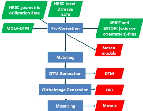
Area-based matching is performed on the 2 pairs derived from the three stereo images using the DLR-VICAR programme. Conjugate points are matched to nadir image by iteratively processing different pyramid levels, starting from the lowest resolution, sampled by bilinear sampling (Baltsavias, 1991). Matching is done for each off-nadir image, paired with the nadir image. The cross-correlation algorithm is used for discrete pixel position approximation. Sub-pixel accuracy is reached by a least squares method(Ackermann, 1983). The 3D object points are generated from tie-point coordinates and interpolated as map projected DTMs. This processing chain is shown in Figure 1.
Figure 1. Processing Chain used for Generating DTMs and ORIs by DLR-VICAR (simplified, based on Scholten et al.,
2005)
2.2 Modification by Kim & Muller (2009)
The matching process is modified with a script based on IDL (Kim and Muller, 2009). Area-based matching is performed using a region-growing variant of the Gruen ALSC matcher (Adaptive Least Square Correlation) within the Gotcha (Gruen-Otto-Chau) algorithm (Gruen, 1985; Otto and Chau, 1989; Shin and Muller, 2012). Matching is done with a MOLA basemap and DTM produced with the DLR-VICAR Processing Chain.
The variance and covariance matrix for each match is defined and a maximum eigenvalue (so-called precision value) is calculated. Lowest maximum eigenvalue is calculated for 5 iterations. Iterative scheme is done for different matching window sizes, from larger windows, to obtain base matching results to smaller windows to obtain more detailed results. The maximum grey level difference is taken as the value for each matching (Kim et al., 2013). Pairwise matching results are then merged. Least squares forward intersection are used for compute 3D points. Interpolation is done to obtain more accurate subpixel extractions. Blunders are reduced by assigning a threshold for intersection accuracy (Kim and Muller, 2009).
After matching points for all channel pairs, a DTM can be produced by grid-point interpolating the result. Level 2 images are first projected to the MOLA basemap to produce level 3 images. After obtaining a DTM, level 3 images are map projected to DTM and then applied to orthorectify the images.
Figure 2 Processing Chain used for Generating DTMs and ORIs by DLR-VICAR method modified by Kim & Muller
(based on Heipke et al., 2007; Kim and Muller, 2009)
3. RESULTS AND ANALYSIS 3.1 HRSC Images with SPRC
At the time of writing, there are 11 189 level 3 and above HRSC and SRC products in nadir view, with 3689 of them level
and available for access. From those, 149 are of latitudes south of 85o S where the SPRC is located.
The 149 sets of images are taken over a timespan of 6 years, from April 2005 until March 2011. That corresponds with 4 Martian winters, from MY 28 until MY 30 according to the Clancy calendar (Clancy et al., 2000), with a distribution of 32 orbits in MY 27 (21.48%), 48 orbits in MY 28 (32.21%), 28 orbits in MY 29 (18.79%), and 2 orbits in MY 30 (1.34%). The images can also be grouped according to their Martian Year. Based on the information, using the HRSC images available, we can analyse SPRC over a timespan of 2 years for all areas and with 3 years timespan for 1.34% data. The vast majority (96.64%) of the images have nadir resolution of 50 m/ pixel and above, with 19 orbits (43.62%) at the maximum HRSC resolution of 12.5 m/pixel. This ensures that the DTMs produced are able to reach a resolution of at least 4 times coarser than the original image resolution, 200 m/ pixel (Heipke et al., 2007).
All 149 sets are available as DTMs and level 4 images processed by DLR, although not as full orbital strips. DTMs and level 4 images available from DLR for latitudes south of 85o are limited to 14 orbits. For HRSC images around the polar region, cloud, dust and low contrast, because of saturation, can reduce the quality of the stereo processing results. In HRSC images, bad quality images are also be caused by other factors, such as occlusions, shadows, image noise, and compression artefacts. For this paper, we processed 24 good quality images for the south polar region.
3.2 Producing DTMs and ORIs
At periapsis, ground resolution of the nadir channel of HRSC images can reach 12.5 m/pixel, with stereo channel resolution typically two times coarser than the nadir channel (Heipke et al., 2007). Because of the elliptical orbit of the satellite, the nadir resolution varies between images covering the same area but also within a single orbital image. In this research, all DTMs are made at a resolution of 200 m/pixel to adjust for the different resolutions of level 2 images, given the lowest nadir resolution of 50 m/pixel. Subsequently, all orbits are orthorectified using a polar stereographic projection with the same parameters, centred on 90o S and 0o E. Similar parameters are necessary to produce mosaiced data without additional steps for projection. The resulting DTM were mosaiced to produce the final DTMs partially covering the SPRC area.
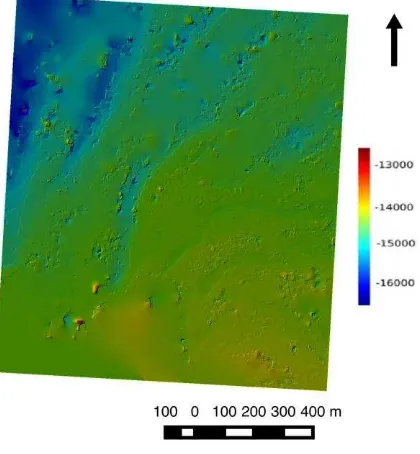
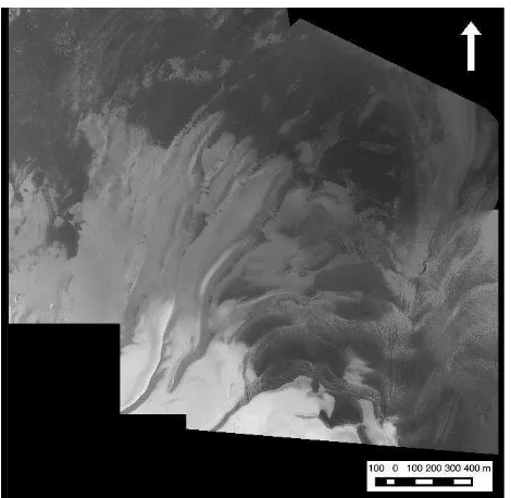
With the DLR-VICAR method modified by Kim and Muller script, DTMs and ORIs of selected orbits are made. HRSC images are taken from south to north for each orbit. Around 15000 lines are processed for each image, each fitting with SPRC positioned within, and to obtain less processing time. An example result is shown for H2162_0000 with SPRC in the southern area as pictured in Figure 3 with DTM produced by both DLR-VICAR processing chain and Kim & Muller modification pictured in Figure 4.
Figure 3. HRSC Image h2162_0000, lines 1-15000 processed with DLR-VICAR, orthorectified to a DTM produced with the
Kim & Muller (2009) Modification
Figure 4. Colourised hillshade image of DTMs: (a) H2162_0000 with the DLR-VICAR method. (b) Kim & Muller
can be seen in Figure 5
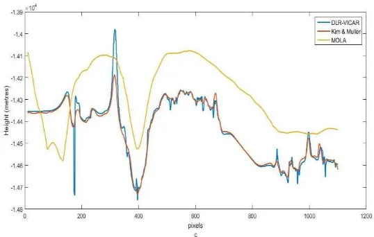
Figure 5 DTM Height Comparison of H2162_0000.for three height profiles
Height profiles were extracted using values obtained in DTM. Height samples are taken for three different height profiles. The resulted DTM from Kim and Muller modified method gives a smoother profile, as seen in the side-by-side comparison between the DTM in Figure 4 and Figure 5. Based on the height profiles in Figure 5, we can see that the height profile is fairly similar for both processing, with smoother profile reached by Kim & Muller modification, reducing the outliers in height profiles obtained by DLR-VICAR method. Both processing are giving similar profiles with MOLA height values, with result from Kim & Muller modified method gives consistently lower height compared to MOLA height values compared to DLR-VICAR method which gives more fluctuative value. This can be corrected by giving adjustment for the height value. Better result can also be obtained by choosing profiles in accordance with MOLA orbits, not values based on interpolation.
The height difference of HRSC DTM processing with MOLA height in the strip for Kim and Muller modified method can be seen in Figure 6. As discussed in the previous part, difference compared to MOLA height values are pretty consistent for the image, with difference in +100 m range in most pixels. Higher differences are obtained around the SPRC edges. These differences might be caused by the need for MOLA footprints to have slopes <2º where even though the footprints are 170m, they do not represent the height discontinuities on the surface.
Figure 6 Height difference map for H2162_000 (DLR-VICAR + Kim & Muller with MOLA-DTM. Positive values means
higher MOLA-DTM profiles)
3.3 Examples of Overlapping Images
From processed images, orbits with overlapping areas in SPRC are selected for analysis. Demonstrated (Figure 7) is overlapping area for H2162_0000, H2183_0000, H2228_0000, H4144_0000 and H4162_0000. Area overlapping between these five images is 4,268.25 m2, with 213,512.03 m2 total overlapping areas for two images or more, with more than about a third containing the SPRC.
Figure 7 Overlapping areas of H2162_0000, H2183_0000, H2228_0000, H4144_0000 and
H4162_0000 with SPRC visible
From the five orbits used as a test, three were taken in MY 27/ 2005 (orbits 2162, 2183, and 2228) and two were taken in MY 28/2007 (orbits 4144 and 4162). Images are then compared for
the span of one martian year/ two years by differentiating pixel values between the images.
Table 1 Statistics of Images Used as Sample
Image Name Date Acquired
Resolution of Nadir image (metre/ pixel)
Resolution of Stereo
Images (metre/pixel)
H2162_0000 2005-09-20 25 50
H2183_0000 2005-09-25 25 50
H2228_0000 2005-10-08 25 50
H4144_0000 2007-03-29 50 100
H4162_0000 2007-04-03 50 100
As the images are orthorectified by the DTMs produced by the methods outlined above, it was assumed that the images had been corrected planimetrically. The two images can be analysed visually by flickering between the two images. Visually it seemed that there is no change in brightness between the two images. By differentiating brightness values between images within the two sets, changes in pixel values between images in between periods of two years can be detected. Figure 8 shows a difference map between the orthorectified images of H2162_0000 and H4162_0000. After normalisation, we can see than there are positive pixel differences in the SPRC area. The albedo of the area was lower for H4162_0000 compared to H2162_0000. Future research is required to better understand where these differences come from. For example, are these due to differences in solar/view azimuths for the two images or if not a multi-angular artifact, are these differences due to a reduction of the ice layer thickness or due to other factors as yet unknown..
Figure 8 Differences displayed as a grey-level between orbit 2162 and 4162 (normalised, only showing
overlapping area)
4. CONCLUSIONS AND FUTURE WORK In this work, an analysis of HRSC images above a latitude of -85o S has been perfomed to try to classify the images and identify the possibility to process images and detect changes. Orbits over the South Polar Residual Cap are identified. HRSC Level 2 images were processed with DLR-VICAR with the modifications developed by Kim & Muller (2009) to produce Digital Terrain Models (DTMs) and Orthorectified Images (ORIs). Not all areas of SPRC have been mapped and mosaiced with this method. A few processed images were analysed for overlapping areas to identify possible changes in brightness where a few areas have been identified for further study. Future work aims to process all areas of SPRC, using HRSC as a basemap to produce DTM for other Mars images, correcting the height result with MOLA, as well as more thorough research into any possible changes which can be identified in overlapping areas.
ACKNOWLEDGEMENTS
The first author would like to acknowledge support for her studies from the Indonesian Endowment Fund for Education, Ministry of Finance, Republic of Indonesia. Part of the research leading to these results has received funding from the STFC “MSSL Consolidated Grant” ST/K000977/1 and partial support from the European Union’s Seventh Framework Programme (FP7/2007-2013) under iMars grant agreement n˚ 607379. We also acknowledge use of the ESA/DLR HRSC images.
REFERENCES
Ackermann, F., 1983. High Precision Digital Image Correlation. Proceedings 39th Photogrammetric Week, pp. 231-243.
Baltsavias, E.P., 1991. Multiphoto geometrically constrained matching. Doctoral dissertation, Diss. Techn. Wiss. ETH Zürich, Nr. 9561, 1991. Ref.: A. Gruen; Korref.: BP Wrobel).
Bibring, J.-P., Langevin, Y., Poulet, F., Gendrin, A., Gondet, B., Berthé, M., Soufflot, A., Drossart, P., Combes, M., Bellucci, G. Moroz, V., Mangold, N., Schmitt B. and the OMEGA Team, 2004. Perennial water ice identified in the south polar cap of Mars. Nature, 428(6983), pp.627-630.
Campbell, J, Sidiropoulos, P., and Muller, J.-P., 2015. Mapping of Swiss Cheese Terrain Using HRSC and CRISM Data. ISPRS Working Group IV/8 Planetary Mapping and Spatial Databases Meeting.
Clancy, R. T., Sandor, B. J., Wolff, M. J., Christensen, P. R., Smith, M. D., Pearl, J. C., Conrath, B. J., and Wilson, R. J., 2000. An intercomparison of ground-based millimeter, MGS TES, and Viking atmospheric temperature measurements: Seasonal and interannual variability of temperatures and dust loading in the global Mars atmosphere. Journal of Geophysical Research: Planets 105, pp. 9553–9571.
Gruen, A., 1985. Adaptive least squares correlation: a powerful image matching technique. South African Journal of Photogrammetry, Remote Sensing and Cartography, 14(3), pp.175-187.
Heipke, C., Oberst, J., Albertz, J., Attwenger, M., Dorninger, P., Dorrer, E., Ewe, M., Gehrke, S., Gwinner, K., Hirschmüller, H., Kim, J.R., Kirk, R.L., Mayer, H., Muller, J.-P., Rengarajan, R., Rentsch, M., Schmidt, R., Scholten, F., Shan, J., Spiegel, M., Wählisch, M., Neukum, G. and the HRSC Co-Investigator Team, 2007. Evaluating planetary digital terrain models—The HRSC DTM test. Planetary and Space Science, 55(14), pp.2173-2191.Heipke, C., Oberst, J., Albertz, J., Attwenger, M., Dorninger, P., Dorrer, E., Ewe, M., Gehrke, S., Gwinner, K., Hirschmüller, H., others, 2007. Evaluating planetary digital terrain models—The HRSC DTM test. Planet. Space Sci. 55, 2173–2191.
Kim, J.R., Lin, S.Y., Choi, Y.S. and Kim, Y.H., 2013. Toward generalized planetary stereo analysis scheme—Prototype implementation with multi-resolution Martian stereo imagery. Earth, Planets and Space, 65(7), pp.799-809.
Kim, J.R. and Muller, J.P., 2009. Multi-resolution topographic data extraction from Martian stereo imagery. Planetary and Space Science, 57(14), pp.2095-2112.
Kirk, R.L., Howington-Kraus, E., Galuszka, D., Redding, B., Hare, T.M., Heipke, C., Oberst, J., Neukum, G. and HRSC Co-Investigator Team, 2006, March. Mapping Mars with HRSC, ISIS, and SOCET SET. In 37th Annual Lunar and Planetary Science Conference (Vol. 37).
Neukum, G. and Jaumann, R., 2004, August. HRSC: The high resolution stereo camera of Mars Express. In Mars Express: The Scientific Payload (Vol. 1240, pp. 17-35).
Otto, G.P. and Chau, T.K., 1989. ‘Region-growing’algorithm for matching of terrain images. Image and vision computing, 7(2), pp.83-94.
Piqueux, S., Byrne, S., Richardson, M.I., 2003. Sublimation of Mars’s southern seasonal CO2 ice cap and the formation of spiders. Journal of Geophysical Research: Planets, 108(E8).
Plaut, J.J., Picardi, G., Safaeinili, A., Ivanov, A.B., Milkovich,
Scholten, F., Gwinner, K., Roatsch, T., Matz, K.-D., Wählisch, M., Giese, B., Oberst, J., Jaumann, R., Neukum, G., 2005. Mars Express HRSC data processing–Methods and operational aspects. Photogramm. Eng. Remote Sens. 71, 1143–1152.
Shin, D. and Muller, J.P., 2012. Progressively weighted affine adaptive correlation matching for quasi-dense 3D reconstruction. Pattern Recognition, 45(10), pp.3795-3809.
Sidiropoulos, P. and Muller, J.P., 2015a. Coregistration of high-resolution Mars orbital images. In EGU General Assembly Conference Abstracts (Vol. 17, p. 7496).
Sidiropoulos, P. and Muller, J.P., 2015b. On the status of orbital high-resolution repeat imaging of Mars for the observation of dynamic surface processes. Planetary and Space
Titus, T.N., Cushing, G., Pathare, A., Christensen, P.R., Byrne, S., Ivanov, A.B., Ingersoll, A., Richardson, M., Kirk, R.L., Soderblom, L.A. and The THEMIS Team, 2004, March. Intra-annual variations of the Martian swiss cheese terrain. In Lunar and Planetary Science Conference (Vol. 35, p. 2005).