POWER MANAGEMENT CONTROL OF A HYBRID PV-GENSET SYSTEM USING
ZELIO LOGIC SMART RELAY
Soeprapto1, Unggul Wibawa2, Mahfudz Shidiq3
1,2,3
Department of Electrical Engineering Faculty of Enegineering Brawijaya University Email: [email protected], [email protected], [email protected]
ABSTRACT
Power management control using Zelio Logic
Smart Relay is applied as a means to make
automatic power transition from battery to generator and vice versa. The design of a hybrid system in a laboratory scale is described including the design of software part using
Zelio Soft2 (ANONIM 3, 2014). The
experiment results show that the values of voltage and power output of the solar cell will increase with the increasing intensity of the sun, while the current will be decreasing. The current sensor used in the system is able to detect the linear changes of current flowing into the load and to respond in a form of voltage to be inputted into Zelio. The automatic operation of genset can be performed properly and the SFC optimum value of the genset of 2.8 kW, 220 V, 50 Hz is 0.67 l/kWh under 72% loading of the generator capacity. Automatic switching of the hybrid system can be realized based on the sensing results of battery voltage and load voltage with the help of Zelio. Load is supplied through the battery inverter when the battery voltage exceeds its voltage, it is supplied directly from the genset and the relay is activated to charge the battery.
Keywords: Zelio Logic Smart Relay, Current
sensor, Charge the battery
1. INTRODUCTION
Energy is one of the main factors influencing the economic growth of a country. Its consumption level is indirectly related to the development level of a country, so that the concern of energy reserve must always be considered in order to create a sustainable development. Many efforts to conserve energy should be accompanied with innovation to explore renewable energy sources.
Indonesia is a tropical country so get sunlight with high intensity throughout the year. This means that the potential use of solar energy is enormous.Along with the development of technology, human life is very dependent on electrical energy where electricity demand progressively increasing so that the higher the costs. However, the cost of these example the use of PV systems combined with generator (PV-generator hybrid system). By applying this hybrid system, can improve the efficiency of genset systems, reducing dependence on fuel supply, and maintain a stable supply of electricity (FITRIANA, I., 2003). However, varying electrical load requirements and light intensity change caused performance hybrid PV-genset system is not optimal. To meet the electricity needs of optimal, it is necessary to control the power management of the hybrid system. Therefore, this paper presents the "Power Management Control in Hybrid PV-Generator System Using Zelio Logic Smart Relay”.
This paper aims to get the design of hybrid PV-generator system using Zelio Logic smart relays include: (1) the parameters of voltage, current, and power solar cell; (2) the performance of the load current sensor; (3) automation genset circuit performance and the value of the Specific Fuel Consumption (SFC) is optimal; (4) the performance of Zelio in the switching system
2. DESIGN SYSTEM
2.1 General Description
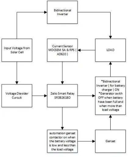
(genset), and AC load. To implement the system automatically, it is necessary to use the controller Zelio Logic Smart Relay (read: Zelio). Part system that controlled is between the battery energy from solar panels and genset based on the amount of load attached.
Figure-1. Block diagram of the power management control system hybrid pv-genset
2.2 Design Current Sensor
Current sensor used is a non-invasive MDCSEM5A (ANONIM 2, 2010). The current sensor output voltage form but still small so we need a signal booster. Thus, in this design are used Signal Conditioning Circuit (SCC) is instrumentation amplifier AD620. SCC is designed such that the output can provide input to the Zelio.
Figure 2. Block diagram of the design of the current detector load.
2.3 The design of voltage divider circuit
The design of the voltage divider circuit is needed to lower the output voltage of the battery into the range of 0-10 V (ANONIM 2, 2010). This is because Zelio only able to detect the input voltage up to 10 V.
Figure 3. The voltage divider circuit.
The magnitude of the output voltage generated depends on the value of R1 and R2 in accordance with the equation:
in
2.4 Design Automation Genset
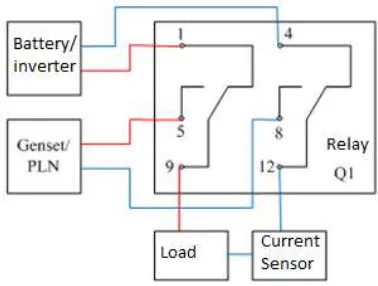
Design automation genset is done by using a relay instead of the genset manually switch contacts. The relay will be conditioned by the Zelio so that the genset can on and off automatically. Replacement of the genset manually switch the relay contacts are shown in Figure 4.
Figure 4. The series of automation generator.
2.5 Design Program
Designing software (program) is done using computers (PCs) and software Zelio Soft 2. The programming language used is the ladder diagram (ANONIM 3, 2014). This program is used to control the energy of the battery and the genset based on the load attached, as well as controlling the ON-OFF of the genset for the system to operate properly and optimally.
2.5.1 Design Transition Power Sources
between Battery and Genset
Figure 5. The transition between the battery and generator power.
2.5.2 Design of Automatic Starting and
Running the Genset
Design of Automatic Starting on the genset can be seen in Figure 6. This follows.
Figure 6. Automatic starting the generator.
2.5.3 Design Delay OFF on Genset
This design can be seen in Figure 7 below.
Figure 7. Automatic starting the generator.
2.5.4 Relay Design for Battery Charging
Designing relays for battery charging is shown in Figure 8 below.
Figure 8. Relay for charging the battery.
3. CONFIGURATION INPUT / OUTPUT ON ZELIO
Zelio has 26 I / O consists of 16 inputs and 10 outputs. The configuration of the input / output on Zelio used in this design are shown in Table 1.
Ib and Ic is analog inputs on the Zelio respectively is used to detect the battery voltage and the voltage Ib and Ic load so is the amount of DC voltage in volts (V).
Table 1. Configuration of I/O on the Zelio No. Input Description output Description 1. Ib Battery
Voltage Sensor
Q1 Genset contact coil
Voltage Sensor
contact coil
3 - - Q3 Bi-inverter
relay for charging
4 - - Q4 Generator
shutdown relay
4. TESTING AND ANALYSIS
4.1 Testing of Solar Cell
Solar cell testing aims to determine the amount of the value of the output of the solar cell in the form of voltage, current and maximum power. Solar cell testing conducted on Thursday, July 17th, 2014 with the condition of 25 ° C at 10:00 to 12:00 pm. Test sites were in 112.612 west latitude and 7.949 south latitude. Solar cell testing circuit is shown in Figure 9. The test results are shown in Table 2.
Figure 9. The series of solar cell testing.
Table 2. Results of testing solar cell 205 Wp
Figure 9. Graph of the current-voltage characteristic testing.
Table 3 Comparison of the solar cell parameters Solar Cell
Parameter
Specification Value
Measurement Value
Open Circuit Voltage (VOC)
35,2 V 33,07 V
Short Circuit Current (ISC)
7,91 A 6,9 A
Time (WIB) Voc (V) Isc (A) Power (W) Sun intensity ( LUX ) Weather Condition 10:00 29.5 6.9 203.55 79200 Bright 10:30 30.07 6.88 206.8816 80500 Bright 11:00 31.09 6.85 212.9665 92700 Bright 11:30 31.71 6.8 215.628 94000 Bright 12:00 33.07 6.6 218.262 96500 Bright
From the test results of the solar cell can be seen that the biggest ISC is 6.9 A, while the
largest VOC is 33.07 V. And the graph on the
solar cell IV curve is non-linear and inversely. The larger the voltage value VOC, then the
smaller the value of the current ISC.
4.2 Load Current Detector circuit testing
The purpose of testing is the load current detection circuit for detecting calibrate the block diagram and the load current is used to determine the value of the current flowing to the load. Block diagrams and circuit test current sensor is shown in Figure 10. Current sensor test results are shown in Table 4.
osciloscope
Figure 10. Block diagram of the test circuit current sensors.
Table 4. Data MDCSEM5A sensor output voltage and SCC AD620.
Based on test data indicate that the current sensor output voltage follows the AC waveform of the load. Peak voltage value for current 0.44 A to 4.75 A is 0.128 V to 1.28 V. The value of the effective voltage is 0.084 V to 0.89 V. The effective value of the output voltage SCC is
Figure 11. Graph output voltage and current sensor SCC.
4.3 Testing the voltage divider circuit
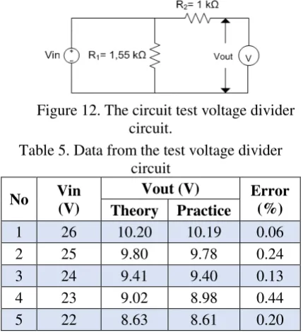
Voltage divider circuit testing is done to calibrate and determine the output voltage of the battery to be conditioned in the range of 0-10 V that can be detected by Zelio. Testing circuit is shown in Figure 12. The test results are shown in Table 5.
Figure 12. The circuit test voltage divider circuit.
Table 5. Data from the test voltage divider circuit
Based on the test data in Table 5. The obtained value of the lowest error of 0.06% and the highest error of 0.44%.
4.4 Genset Automation Testing
This test was conducted to test the automatic starting on generators by using relays automation generator has been designed previously.
Theory Practice Theory Practice Theory Practice
0 0.00 0 0.00 0 0.00 0 0 0 0.00 0 0.00
100 0.45 0.44 3.31 0.128 0.09 0.084 7.75 1.28 0.91 0.82 10.38
200 0.91 0.87 4.49 0.248 0.18 0.172 1.95 2.48 1.75 1.68 4.38
300 1.36 1.3 4.90 0.368 0.26 0.24 8.42 3.68 2.60 2.52 3.26
400 1.82 1.73 5.10 0.52 0.37 0.326 12.79 4.8 3.39 3.36 1.02
500 2.27 2.17 4.73 0.64 0.45 0.408 10.92 6.2 4.38 4.22 3.89
600 2.73 2.59 5.30 0.74 0.52 0.492 6.35 7.4 5.23 5.07 3.21
700 3.18 3.03 5.01 0.86 0.61 0.576 5.57 8.6 6.08 5.93 2.55
800 3.64 3.46 5.10 0.98 0.69 0.64 8.28 9.6 6.79 6.78 0.12
900 4.09 3.89 5.16 1.1 0.78 0.72 8.03 11 7.78 7.61 2.21
1000 4.55 4.3 5.71 1.24 0.88 0.81 8.25 11.6 8.20 8.17 0.40
1100 5.00 4.75 5.26 1.28 0.91 0.89 1.70 12.4 8.77 8.56 2.43
V-effectif (V)
Vpeak (V) Vpeak (V) V-effectif (V) V-output RPS (V)
Error (%) Sensor Output Voltage
Current (A)
Voltage Regulator DC
Zelio Autmation Relay Generator
Figure 13. Block diagram of test automation generator.
Table 6. Data from the test automation generator.
Based on the test data in Table 6. when the input battery voltage of 9.7 V and Ib = Ic = load voltage of 3.8 V, conditions relays and genset OFF. At the time of Ib = 9.3 V and Ic =9.5 V, the condition of the generator and relay ON. It can be concluded that the automation generator circuit can work and function properly.
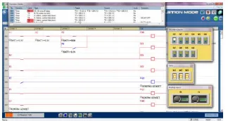
4.5 Testing Program
Program in Zelio important role in the operation of the system. It is necessary to test the software by means of simulations using the features found in the software Zelio Soft 2. This is done to determine whether the program can be run properly.
4.5.1 Testing Transition Program Power
Sources from Battery to Genset
Figure 14. Simulation transition program from power sources battery to genset.
4.5.2Testing Automatic Starting Program at Genset
Figure 15a. Simulation Automatic Starting ON program at Genset.
Figure 15b. Simulation Automatic Starting OFF program at Genset
4.5.3 Testing Program Relay for Battery Charging
Figure 16. Simulation for charging relay.
4.5.4Testing Delay OFF Program on Genset
Figure 17. Simulation OFF delay program on the generator.
4.6 Testing SFC Genset
Tests SFC genset conducted to determine the characteristics of the amount of fuel consumption so that the genset can be used as a reference in implementing the hybrid system.
In this test, the genset used is the genset with a power capacity of 2.5 kW. Based on the test data in Table 7. The values obtained SFC generator as follows. At the time of the genset under load of 100 W (4% of the capacity of the generator), the value of SFC is very large in the amount of 6.59 l / kWh. And when the generator is loaded to 72% of the capacity of the generator, the SFC is an optimum value which is equal to 0.67 l / kWh
Figure 19. Graph SFC characteristics genset
Based on Figure 19 it can be seen that the value of SFC generator decreases with increasing percentage loading. The greater the percentage of load supplied genset, the smaller the value of SFC generator.
4.7 Testing Overall System
Testing the whole system is done to determine if the system can run well. In this test, the battery is simulated by using a dc voltage regulator which is then connected to the inverter so that it can supply the load. Whereas, the energy source of the genset is represented by PLN. In this test, switching the two sources (PLN and inverter) is represented by a single relay (Q1: NO and NC) to keep these two sources are not met.
Figure 20. Block diagram of the whole system testing.
Table 9. Testing the overall system
Based on the test results in Table 9, when the battery voltage is 24 V was given a load of 25 W, input Ib = 9.0 V, Ic = 5.6 V, the condition of the relay Q1 (NC) active, Q4 ON. This indicates that the load is supplied by the battery via the inverter, and the condition of the genset / PLN is still OFF. Whereas, when the battery voltage of 23.5 V was given a load of 40 W, input Ib = 8.8 V, Ic = 9.3 V, the condition of the relay Q1 (NO) is active, Q4 OFF. This means that the load is supplied by the genset / PLN. Thus, it can be concluded that the energy transition system battery and the genset can work well.
5. CONCLUSION
Based on the results of the design and testing have been described, some conclusions can be drawn:
2. Current sensor and SCC are used in the system is able to detect changes in the current flowing to the load linearly with the response form the output voltage becomes the input Zelio.
3. Automation generator circuit can work and function properly. In addition, the measurement of the generator SFC, SFC optimal value obtained is of 0.67 l / kWh at the time of loading 72% of the capacity of the generator.
4. The transition energy from the battery to the generator and vice versa can be done by Zelio well. Hybrid system works based on battery voltage sensor (Ib) and load voltage (Ic). When Ib> Ic, the load is supplied by the battery and the generator condition is
OFF. When Ib≤Ic, ON generator to supply
the load and relay ON charger to charge the battery.
REFERENCES
ANONIM1. (T.t.). Solar Power Medium-Large
Scale (Hybrid-Grid Interractive). (PT. Azet
Surya Lestari) Retrieved 6 April 2014, from http://www.azetsurya.com
ANONIM2. 2010. 5A Non-Invasive AC Current
Sensor Module. Accessed July 26, 2014,
from http://www.vcc2gnd.com
ANONIM3. (T.t.). Smart Relays. Accessed March 17, 2014, from Schneider Electric: http://www.schneider-electric.ca
ANONIM4. 2003. Analog Device-Low Cost Low Power Instrumentation Amplifier
AD620. Catalog book
FITRIANA, I. 2003. Sustainable Energy
Systems and Management (SESAM), MSc.
Thesis. Flensburg.
HANSEN, A. D. et al. 2000. Model for a
Stand-Alone PV System. Roskilde: Riso National
Laboratory.
KARIANA, A. (T.t). Characteristics Study of Current-Voltage (IV curve) in Single Cells
polycrystalline silicon as well as modeling.
Proceedings of the Scientific Meeting of Central Java and Yogyakarta HFI XXV, XXV, pp. 163-166. DIY.
SIAHAAN, P. 2013. Performance Testing Generator Power Plant Biogas from
Wastewater mills. SINGUDA ENSIKOM,
3 (1), 23-28.
SUMANTO. 1996. Synchronous machine. Yogyakarta: Andi.
TRIHADI, S. 2000. Draft Technical and Implementation of Power Systems Hybrid
PV-Diesel in Sulawesi. Scientific Journal of