VISUAL UAV TRAJECTORY PLAN SYSTEM BASED ON NETWORK MAP
XiuLi Lia *, ZongJian Linb,GuoZhong Sub, BoYi Wuc a
Wu Han University, Wu Han, China.
b
Chinese Academy of Surveying and Mapping, Beijing, China.c
Foundation Geographical Information Courtyard of Shanxi Province,Shanxi Province, China.
Commission I, ICWG I/V
KEY WORDS: Trajectory Planning, Image, UAV, Google earth, Map, Parameter
ABSTRACT :
The base map of the current software UP-30 using in trajectory plan for Unmanned Aircraft Vehicle is vector diagram. UP-30 draws navigation points manually. But in the field of operation process, the efficiency and the quality of work is influenced because of insufficient information, screen reflection, calculate inconveniently and other factors. If we do this work in indoor, the effect of external factors on the results would be eliminated, the network earth users can browse the free world high definition satellite images through downloading a client software, and can export the high resolution image by standard file format. This brings unprecedented convenient of trajectory plan. But the images must be disposed by coordinate transformation, geometric correction. In addition, according to the requirement of mapping scale ,camera parameters and overlap degree we can calculate exposure hole interval and trajectory distance between the adjacent trajectory automatically . This will improve the degree of automation of data collection. Software will judge the position of next point according to the intersection of the trajectory and the survey area and ensure the position of point according to trajectory distance. We can undertake the points artificially. So the trajectory plan is automatic and flexible. Considering safety, the date can be used in flying after simulating flight. Finally we can export all of the date using a key
.
1.INTRODUCTION
UAV remote sensing technology takes Unmanned Aerial Vehicle as remote sensing platform, uses Color, Monochrome, Infrared photographic technique to shoot the image,and processes image information use the computer. It's advantages are nimble and flexible, simple and reliable, excellent properties, high resolution. trajectory plan is one Basal and important task of acquiring aerial image and other remote sensing data.
2.OBTAIN THE IMAGE DATA
2.1 A method of obtaining the image data
The data source is that the map data of every province is updating. On the one hand, we can transform the electronic map
into MAPINFO format (. GST document) and use them as background map. On the other hand, we can choose scanning map whose format is grid, before using. Image registration was needed.
2.2 Another method of obtaining the image data
If there is no way to get known data, another method to obtain the image data is downloading them from Google Earth. And the downloading image is more intuitive than the existing map data. GETSCREEN downloads satellite images according to the grid you draw and automatic split joint, in addition you can set up the height. The format of the images is JPG and BMP, JPG format generates a map file which contains eleven options of the image information, as
follows: longitude of the first point, latitude
of the first point, height, the resolution X, Y, transverse pixel, longitudinal pixel,
International Archives of the Photogrammetry, Remote Sensing and Spatial Information Sciences, Volume XXXIX-B1, 2012 XXII ISPRS Congress, 25 August – 01 September 2012, Melbourne, Australia
longitude of the left, top latitude, longitude of the right, bottom latitude. The projection of Google Earth is improved UTM, but GETSCREEN doesn't consider the projection. So that in large area image dislocation will produce in downloading. Geometric correction is needed before using.
Through the experiment, this setup will puzzle the dislocation before downloading.
(1) C a n c e l t h e o p t i o n
" l a n d s c a p e " o f " l a y e r Settings panel" in Google Earth.
(2) O p e n t h e o p t i o n " o p t i o n " o f t h e d r o p - d o w n list "tool", select "direx" and "safe mode".
(3) B e c a u s e t h e s c r e e n r e f r e s h n e e d s t i m e , increase delay time, and generally under 1000.
(4) S t a r t G o o g l e E a r t h b e f o r e G E T S C R E E N .
(5) Rectify the "height" of GETSCREEN. GETSCREEN hijacks the whole picture of Google Earth to the window, original level of 1024 dpi images are downed to 722 dpi, this will produce the contraction. In this way, the image we get is smaller than the image of Google earth. The correction coefficient is 722/1024 = 0.705.
GetscreenHeight = GoogleEarthHeight* 0.705 Of course, the images need registration.
°: heading overlapping degree, 02 : the
degree to overlap.
4. TRAJECTORY DESIGN
4.1 Idea
The important factors we consider in trajectory design is image acquisition and how import the result to UP30, MAPINFO play a role in series, MAPBASIC solves the role of the series which is the second development language of MAPINFO, because GETSCREEN is developed use MAPBASIC, such as: coordinate system transformation, registration, file format conversion. After developing the trajectory import it to UP30.
4.2 solution method of trajectory
The specific steps of generating trajectory: (1) Draw the survey area (2) Input the flight parameters (3) Produce dot data. The system will automatically calculate the flight navigation points which guide to fly according to the specific requirements of the homework. Hypothesis the flying area is P1, P2, P3,
P4, P5 ... Pn , n is the point number of the survey
area Hypothesis longitude is x axis direction and latitude is y axis direction in the process of calculation, the unit of longitude and latitude is degree
3. FLIGHTPARAMETERS
Flight parameters are the foundation of air line design, and are another big module beyond the background picture. The most important parameters are adjacent trajectory interval and baseline length. Computation formula is as follows:
D = 2* H * tan($,) *(1 — Oj) B = 2* H *tan(<92
)*(1 — o2)
D: adjacent trajectory interval, B: baseline length, ^: Angle of view in parallel flight direction, 0 2: Angle of view in vertical
flight direction, H: the flying height,
International Archives of the Photogrammetry, Remote Sensing and Spatial Information Sciences, Volume XXXIX-B1, 2012 XXII ISPRS Congress, 25 August – 01 September 2012, Melbourne, Australia
YD = YD„ D cos0
111000
When K < 0:
Figure 1 .Process of algorithm
(1) Reading angular point
coordinates of measuring area using "ObjectNodeX" and "ObjectNodeY" function, calculating necessary data according to known data for trajectory, such as : adjacent trajectory interval, baseline length, slope K, maximum and
minimum value of X -, X ■ , minimum
m ax min 7
value of Y- X
mm .
(2) In order to guarantee each piece produced in the area of the trajectory.
(3) Solve the equation of linear 0 according to coordinate of P1 and slope k. This equation and L line intersect in D (XDo, YD
° ),and: XD0 = X
YD = K * XDa + Y _ K * X (4) Solve the
equation of linear 1 according to
coordinate of D and slope k, there is a problem coordinate system is latitude and longitude coordinate system, but the unit of adjacent trajectory interval is meter, conversion between units is needed.
©The distance between two points in the same latitude = bad of longitude * 111 km *
Cos (latitude).
©The distance between two points in the same longitude = bad of latitude * 111 km.
The method to calculate the coordinate of point D1 is distances component. Division
adjacent
trajectory interval into two components A , Ay
D ' s coordinates are as follows: D * sin 0
XD. = --- D --- + XD„
1
111000*cosYD, 0 0 = arctan K
AX = D * sin(180 - 0) = 111000* (XDl -
XD0 )* cosYD AY = D *cos(180 - 0) =
111000* (YD0 - YD)
D' coordinates are as follows: D * s i n 0
XD = —D — + XD,, 1
111000*cosYD10 yD = YD + Dcos0 1 0
111000
© Solve the equation of trajectory according to
coordinate of D and slope k.
©Solve the coordinates of the intersections trajectory and boundary equation, and judge whether
the intersection is in the segment, if they are in the
segment, they are initial value of trajectory point.
(7) Expanding initial value of trajectory
point for one baseline length, and they are the point coordinates of trajectory point.
(8) Repeat 4-5 steps to solve each
trajectory point YD of respectively trajectory, and judge n, when n < Y mm, out of circulation.
©When K does not exist, expanding trajectory equation along the X axis. The method of shoveling trajectory point is invariant
5. RESULT
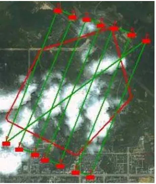
UP30 determines the length of the trajectory and direction according to the starting point and the end point .It creates trajectory on the basis of adjacent trajectory interval and the number of trajectory along with swerve. The shortcoming of this design method is that it dose not design judging by the area of flying, there are some unnecessary flight, so that time and resource is wasted. Figure 3 shows the original design method
International Archives of the Photogrammetry, Remote Sensing and Spatial Information Sciences, Volume XXXIX-B1, 2012 XXII ISPRS Congress, 25 August – 01 September 2012, Melbourne, Australia
After the improvement the advantage of the trajectory comparing to the previous trajectory:
(1) Because the trajectory is designed On the basis of the boundary of the survey area, this will reduce redundant shoot and improve image use ratio.
(2) Trajectory is designed on the paper in traditional operation mode, and operator redraws it in Field Surveying. Trajectory in This system is designed directly in the electronic map and direct introduction them to flight controlling system which will reduce the trouble in field work.
(3) It has supernal automaticity and is coincident with the idea automation.
REFERENCES:
[1] ChangAn Liu, 2003.Research on UAV trajectory planning method. Xi
'an: Xi'an technological university.
[2] HaiTao Ba, 2006.Research
on UAV path planning method. Xi'an: Xi'an technological university.
[3] Wei Liang, Xin Guo Li, 2008. Low altitude trajectory design based on pretreatment digital maps. Flight mechanics,26 (4) : pp.81-85.
[4] Ping Du, Chun Yang,
1999. Summarize of trajectory design algorithm of aircraft. Flight mechanics, 33(2), pp. 13- 18.
[5] Hong Xia Cui, Zong Jian
Lin, 2005. Jie Sun. Research on UAV remote sensing monitoring system. Bulletin of Surveying and mapping, (5), pp. 11-14.
[6] LunJi Ma, RuiSheng Ma,
ZongJian Lin, etc. 2005.Preliminary study on Micro Air Vehicle remote sensing
application. Journal of Guangxi
Meteorology, (9), pp. 180-181.
[7] Specification Of UP30 the
general UAV drive system. BeiJing: Beijing pilotless UAV technology Co, LTD. 2006.
[8] YingYing Cui, Ai Wu
Zhang, ShuMin Wang, Chao Jiang,2010.Research on unmanned airship remote sensing system. Bulletin of Surveying and mapping,pp.268-271.
[9] YangBo Zhu, Jian Jiao,
QiMing Ceng, Shu Jing Song, Zhao Yong Zhang,2007.Research of Remote sensing mission design and trajectory design m e t h o d . B u l l e t i n o f S u r v e y i n g a n d m a p p i n g , ( 8 ) , pp.16-19 .
[10] Bin Hao, Xue Dong
Fang, Yu Tang, 2010 .The application of lectronic chartc in trajectory design.Paper of civil aviation flight university of china, (1 ),pp. 15-17.
[11] ZiMing Xiong, Wen Ge,
2007.Design and implementation of UAV ground monitoring system based on GIS. Marine charting,.27 (4) ,pp.54-56.
[12] Dong Liang Wang, You Chuan Wan, Jing ZhongXu, XuDong Lai,2011.Trajectory design of airborne radar based on DEM the airborne lidar. Surveying and mapping science, 4(1), pp. Figure 2. previous trajectory
Figure 3:New trajectory
International Archives of the Photogrammetry, Remote Sensing and Spatial Information Sciences, Volume XXXIX-B1, 2012 XXII ISPRS Congress, 25 August – 01 September 2012, Melbourne, Australia