GEOLOGICAL MAPPING OF LUNAR CRATER LALANDE: TOPOGRAPHIC
CONFIGURATION, MORPHOLOGY AND CRATERING PROCESS
B. Li a, b*, Z.C. Ling a, J. Zhanga, J. Chen a, C.Q. Liu a, X.Y. Bi a
a Shandong Provincial Key Laboratory of Optical Astronomy and Solar-Terrestrial Environment; Institute of Space Sciences,
Shandong University, Weihai, China. - [email protected] b Key Laboratory of Lunar and Deep Space Exploration, Beijing, China.
Commission VI, WG VI/4
KEY WORDS: Crater Lalande, Geological mapping, Low-relief bulges, Cratering process, Elevation differences
ABSTRACT:
Highland crater Lalande (4.45°S, 8.63°W; D=23.4 km) is located on the PKT area of the lunar near side, southeast of Mare Insularum. It is a complex crater in Copernican era and has three distinguishing features: high silicic anomaly, highest Th abundance and special landforms on its floor. There are some low-relief bulges on the left of crater floor with regular circle or ellipse shapes. They are ~250 to 680 m wide and ~30 to 91 m high with maximum flank slopes >20°. There are two possible scenarios for the formation of these low-relief bulges which are impact melt products or young silicic volcanic eruptions. According to the absolute model ages of ejecta, melt ponds and hummocky floor, the ratio of diameter and depth, similar bugle features within other Copernican-aged craters and lack of volcanic source vents, we hypothesized that these low-relief bulges were most consistent with an origin of impact melts during the crater formation instead of small and young volcanic activities occurring on the crater floor. Based on Kaguya TC ortho-mosaic and DTM data produced by TC imagery in stereo, geological units and some linear features on the floor and wall of Lalande have been mapped. Eight geological units are organized by crater floor units: hummocky floor, central peak and low-relief bulges; and crater wall units: terraced walls, channeled and veneered walls, interior walls, mass wasting areas, blocky areas, and melt ponds. These geological units and linear features at Lalande provided us a chance to understand some details of the cratering process and elevation differences on the floor. We evaluated several possibilities to understand the potential causes for the observed elevation differences on the Lalande's floor. We proposed that late-stage wall collapse and subsidence due to melt cooling could be the possible causes of observed elevation differences on the floor.
1. INTRODUCTION
In the past lunar geological maps (e.g., Wilhelms and McCauley, 1971), all craters (with diameters larger than 10 km) and their surroundings were mapped as an individual unit named as “crater material”. Thus, the crater rim, wall, floor, central peak and ejecta deposits were not recognizable. Recent and ongoing lunar missions provided higher resolution imagery and terrain data which were not available in the past (Krüger et al., 2016).
In general, impact melts distributed widely on floor and wall of a crater. There is a chaotic landscape in crater floor area owing to its continuous evolution during and after the cratering process. The morphological features and distributions of impact melts in and around craters have been broadly analyzed to understand the process of cratering, especially the relationship of melt movement and emplacement with various cratering parameters (e.g., Krüger et al., 2013; Plescia and Spudis, 2014; Srivastava et al., 2013). The geological settings of impact craters' floors are complex and various in the morphology and topography, thus they are not easy to infer. Geological mapping is a primary tool to interpret complicated terrains by sequentially grouping together materials with similar morphological or componential attributes (Nass et al., 2011; Zanetti, 2015). The resulting geological maps produce the fundamental set of information to understand and interpret the geological history of impact craters.
2. CRATER LALANDE 2.1 Geological setting of Crater Lalande
Crater Lalande (4.45°S, 8.63°W; D=23.4 km) is located on the Procellarum KREEP Terrane (PKT, Jolliff et al., 2000) area of the lunar near side, southeast of Mare Insularum and on the border of highlands and Mare Insularum (Fig. 1). Lalande has a obvious ray system of ejecta materials and can be inferred as a Copernican-aged crater. It has a distinct central peak, well-formed terraces as well as impact melts that occur almost everywhere on the crater floor and wall. Lalande is a complex crater (Jolliff et al., 2006).
Fig.1 LRO wide angle camera (WAC) mosaic (centered on the lunar nearside) showing the geologic setting of highland crater Lalande. The International Archives of the Photogrammetry, Remote Sensing and Spatial Information Sciences, Volume XLII-3/W1, 2017
2.2 The distinguishing features of Crater Lalande
The Christensen feature (CF) value derived from Diviner is sensitive to the silicate polymerisation (Glotch et al., 2010). The standard CF values of Lalande crater and its surroundings are shown in Fig. 2. The average value of CF is ~7.2, which supports the possibility that silicic materials may have been distributed in Lalande and its ejecta deposits.
A gammaray spectrometer onboard the Lunar Prospector spacecraft surveyed the natural radioactivity of the lunar surfaces. Lawrence et al. (1999, 2000) recently presented a method for calculating Th abundance with high pixel resolution and produced a global Th abundance map. In this paper, we extracted the part of the recent global low-altitude (0.5×0.5°, corresponding to ~15 km/pixel) Th map that covered the Lalande (Fig.3). The absolute abundances are given in units of ppm. We can see that Lalande has almost the highest, focused concentration of Th (average value is ~12.6 ppm) on the lunar surfaces.
Fig.2 Overlain on an LRO WAC image, CF value (7.2-8.4) derived from Diviner shows a silicic anomaly.
Fig.3 Th abundance of Lalande overlain on a WAC-mosaic base.
From Fig.4, we found there were some low-relief bulges on the left of Lalande's floor. These bulges are positive reliefs with regular circle or ellipse shapes. Their diameters are from ~250 to 680 meter and their height are from ~30 to 91 meter (Fig. 4b). In addition, Lalande's floor can be divided into three levels as I, II and III according to its elevation difference. In the contour map (Fig.4c) derived from the Kaguya DTM data. The appearance of these bulges and three level terrain structures indicate that crater floor may experience some geological processes after impact event to form current landforms.
Fig.4 (a) The TCO map of the Lalande's floor. (b) LRO NAC mosaic showing low-relief bulges in detail in the south western part of the crater floor. (c) The Kaguya DTM data superposed on the TCO map.
3. IMPACT MELT PRODUCTS OR YOUNG SILICIC VOLCANIC ERUPTIONS
3.1 A candidate for volcanic domes?
There are two types of lunar domes: mare (ordinary) domes and silicic domes. Mare dome are gentler swells, with elevation difference of about 300 m above the plane surface, often have flank slopes <7°. While domes found by Sato et al. (2011) at Compton-Belkovich are silicic domes. One of them is ~500 m in diameter at the base and ~100 m high with flank slopes >20°, indicating a more viscous (silicic) lava composition than mare (ordinary) domes with low-viscosity mare basalt lavas. The Lalande’s floor includes a series of low-relief bulges whose diameters range from ~250 to 680 meter and heights are from ~30 to 91 meter, some with steeply sloping sides. The biggest bulge (Fig. 4b) is ~680 m in diameter at the base and ~90 m high and its maximum flank slope is >20°. The 8 mm features measured by Diviner (Fig. 3) indicate that these low-relief bulges are rich in silica and are significantly different from mare materials surrounding Lalande. These bulges look like silicic domes because of their higher silicic composition and steeper slopes and are in common with these found on Earth, associated with silicic (for example, rhyolitic) volcanism.
3.2 Impact melt productions
Crater Lalande has an obvious ray system, a sharp crater rim and a well-preserved shape which indicate that it is a Copernican-aged crater (Wilhelms and McCauley, 1971). If there are some silicic domes on Lalande’ floor formed after the impact event, there is an evidence for a period of the small and youngest basaltic activities on the lunar surfaces. But, according to previous studies (e.g., Schultz and Spudis, 1983; Hiesinger et al., 2010), it is thought that on the Moon the commonly accepted cessation of basaltic volcanism is at ~1.0-1.2 Ga ago, which is inconsistent with the formation time of these silicic domes on Lalande’s floor. In addition, we found similar bugle features in other Copernican-aged crater floors such as Kepler, Aristarchus and a highland crater Glushko, etc. It is hard to believe that in the Copernicus era, there were a lot of volcanic activities on the Moon. Moreover, there are some no-mare silicic volcanic activities on the Moon, such as northern Lassell massif, Compton-Belkovich volcanic complex and Gruithuisen domes, which are all in early Imbrian and Nectarian era. The International Archives of the Photogrammetry, Remote Sensing and Spatial Information Sciences, Volume XLII-3/W1, 2017
Therefore, the low-relief bulges and floor materials of Lanlande are not likely caused by silicic volcanic activities because they are younger and in Copernican age.
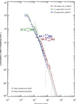
We determined absolute model ages (AMAs) of seven regions (Fig.5) within Lalander crater in all. These regions included two proximal ejecta deposits (E1 and E2), four smooth ponds (M1-M4) and one hummocky area (F1) on the floor. We identified and measured the craters with diameters larger than 50m on these areas and generated their crater size-frequency distributions (CSFDs) in Fig.6. The AMAs for the sum of ejecta and melt pond count areas were 94.2 Ma and 37.6 Ma separately (Fig.6, red line and green line), while the hummocky area on the floor yields an AMA of about 44.1 Ma (Fig.6, blue line). The AMA of crater floor (hummocky area, F1) is similar to the AMA of impact ponds (sum of M1-M4), which means the materials on the floor formed following the impact event and may come from the melts during impact process.
Fig.5 (a) Maps of crater count areas on a NAC mosaic. (b) and (c) are the detailed charts for E1 and M1 count areas.
Fig.6 Average CSFDs of crater count areas of Lalande in Fig.5. The red, green and blue numbers and lines are the AMAs for ejecta deposits, melt ponds and floor materials separately.
On the Moon, there is a class of crater, named as Floor-Fractured Craters (FFCs), which is thought to be formed as a result of magmatic intrusion and sill formation (Jozwiak et al., 2012; Schultz, 1976). FFCs are distinguished by abnormally shallow floors cut by concentric, radial, or polygonal fractures which show clear morphologic differences from fresh impact craters. On floors of almost all FFCs, there are fractures or moat features. Topographically, the moats are either flat, or slope downtoward the wall scarp forming a broad "U" or "V" shape. The Lalande crater has a diameter of ~23.4 km and a depth of ~2.74 km, the ratio of depth and diameter is about 0.12. In addition, the floor of Lalande cannot find "U" or "V" shape
fractures on the floor. Therefore, we think Lalande is not a FFC and there is no subsequent volcanic activities after its impact event. Moreover, there are lack of source vents for the formation of volcanic eruptions on the Lalande's floor. The ratio of diameter and depth and floor morphology do not support an origin related to shallow magmatic intrusion and uplift caused by volcanic eruptions on Lalande's floor.
From the above comprehensive analysis, we believed that the morphology and geologic context of the low-relief bulges and materials on the floor of Lalande were most consistent with an origin as impact melt created during the crater formation. In the next section, we systematically documented the various morphological units on floor and wall of Lalande to understand its cratering process.
4. GEOLOGICAL MAPPING OF CRATER LALANDE Our geological map contains eight geological units organized by crater floor units: hummocky floor, central peak and low-relief bulges; and crater wall units: terraced walls, channeled and veneered walls, interior walls, mass wasting areas, blocky areas, and melt ponds. In our geological map (Fig. 7).
Fig. 7 Geological map of the interior of Lalande was produced using Kaguya TC ortho-images and DTM data. Geological units are described in the text.
4.1 Crater floor units (1) Hummocky floor
This unit covers almost entire floor and surrounds the central peak. The hummocky floor material is interpreted as impact debris piled up on the floor as the crater formed and immediately coated with impact melt (Plescia and Spudis, 2014). This unit covers an area of roughly 82 km2 and is comprised of abundant boulders along with a relatively smaller proportion of smooth material (Fig. 7). In addition, there are many cooling fractures (Fig. 7, yellow lines) on this unit. Fractures form in solidified rock during the cooling of impact melts coming from cratering process (Xiao et al., 2014). These fractures mostly gather in subparallel groups, along the border of crater floor and crater wall (Fig. 8a). In addition, there are some fractures varying in orientation across the crater floor and sometimes forming polygonal patterns (Fig. 8b). The appearance of polygonal fracture patterns is mainly induced by subsidence of the deposits during the process of cooling and solidification (Wilson and Head, 2011).
Fig.8 Fractures in subparallel group (a) and polygonal pattern (b) in Lalande's floor.
(2) Central peak
The central peak of Lalande measures approximately 3.8 km in length from west to east, and is 2.9 km wide. The height of the peak is ~150 m as surveyed by Kaguya TC DTMs. The central peak can be divided into three sub-units (Fig.7) according to its elevation, shape and rock abundance (RA), which are central peak I, central peak II and boulder region. (3) Low-relief bulges
These low-relief bulges are in the left of crater floor and are inferred as the boulders or rubbles covered by impact melt materials formed during impact process (in section 3). These low-relief bulges have very smooth surfaces and few post-craters, and some small boulders or boulder clusters are on them (Fig. 4b). On the left of these bulges, there are several terraces developed on the crater wall resulting in a mottled and hummocky appearance and mass wasting. The strong mass wasting movements may supply a plenty of boulders and clastic materials for the formation of these bulges.
4.2 Crater floor units (1) Terraced walls
We can see that there are several collapses and mass wasting movements on the western part of Lalande's wall. 3-4 well developed terraces with varied widths (~700 m to 3 km) are around the crater wall and define some faults subparallel to the terrace boundaries (Fig. 7). These terraced walls are several hundred meters high and occupy an area of ~320 km2. Impact melts has flowed down from the surfaces of the terraces and are gathered in the gentle areas between high and low terraces to form several melt ponds.
(2) Channeled and veneered walls
Here, channeled and veneered walls are described as plentiful channels, commonly displaying levees, flowing down the crater walls (Zanetti, 2015). Between the channelized flows, there is a relatively smooth surface due to thick veneers of melt materials. This unit has deficiently developed terraces and has higher albedo than other parts of crater walls. When moving down slope, impact melts are thought to be both erosive and depositional (Bray et al., 2010). In Fig.9, we can see that impact melts erode into the walls deeply, but it is unclear if the erosion into the wall is mechanical or thermal, or a combination of the two. Single channels can be seen to extend nearly the >2.8 km length of the crater wall. The area of this unit is ~210 km2.
Fig.9 Channeled and veneered wall and its impact melt flows (yellow lines) in Lalande based on a NAC mosaic map.
(3) Interior walls
The interior walls, different from channeled and veneered walls, are only thinly veneered by impact melt features, and show little channelized melts. This unit is mainly found in the steep northwest, east and south walls, topographically above the channeled and veneered walls. Melt has likely completely drained from these areas, leaving only a thin veneer. These areas occupy roughly an area of 347 km2.
(4) Mass wasting and blocky areas
Mass wasting is material downslope movement driven by gravity (Xiao et al., 2013). It tends to erase surface topographic differences and form gentle reliefs. In Lalande's wall, there are slides and flows of mass movements. Slides are mass downslope movements along ruptures or relatively thin zones of intense shear strain, that separate the sliding material from the more stable underlying planar (Highland and Bobrowsky, 2008). A flow is a form of continuous mass movement in which a combination of loose soil and rock fragments move downslope. Particles in a flow are smaller in size than in a debris slide and they behave like liquid during the placement. The appearance of slides and flows of mass wasting movements on the crater walls are shown in Fig.10a and b.
Fig.10 (a) Rock slides of impact melt sheets on the northern crater wall of the Lalande based on a NAC mosaic image. The yellow and red arrows point to the ends of the rock slides and exposed bedrock on the crater wall separately. (b) Sweeping flows on the eastern crater wall of the Lalande based on a NAC mosaic image. The yellow arrows point to the tracks of the sweeping flows.
Blocky area or rock clusters on the floor are the products of mass wasting movements downslope from the walls. We mapped them as blocky areas in Fig. 7. These blocky areas occupy an area of ~43km2.
(5) Melt ponds
In craters, impact melt deposits are a mixture of real melt with breccias and rock fragments that have been merged during melt movement. Melt ponds are the result of melt flowing to low areas, cooling and solidifying, fracturing the surface The International Archives of the Photogrammetry, Remote Sensing and Spatial Information Sciences, Volume XLII-3/W1, 2017
(Shkuratov et al., 2012). Melt ponds can be easily identified by their relative darker albedo in contrast with the surroundings. In Lalande, melt ponds are found between two adjacent terraces and among the hummocky deposits of wall-derived materials near the eastern crater floor (Fig. 7). They have different sizes, and are confined by area available on the terrace where they formed and by the quantity of melt available when they formed. The surface of ponds is often smooth, and has few post-craters. Fractures can be found on almost all ponded surfaces. These fractures are probably due to thermal contraction of the surface during cooling, but may also be related to extension of the surface (Xiao et al., 2014). The largest terrace melt pond is shown in Fig. 5c. It is located approximately 1.1km above the crater floor, and 1 vertical kilometer below the crater rim. This melt pond is approximately 0.5 km wide and 2.1 km in length along the terrace, and has a surface area of ~1.1 km². There are several fractures approximately paralleling with the right side of the melt pond.
5. GEOLOGICAL MAPPING OF CRATER LALANDE According to previous studies, the elevation differences on the crater floors, are a relatively general phenomenon, may be caused by the following reasons: (1) material from wall collapse piling up on the neighbouring floor (Margot et al., 1999), (2) differential subsidence due to cooling of the melt column (Xiao et al., 2014), (3) melt movements during the early stages of the crater formation and (4) impact conditions (Hawke and Head, 1977). Here, we evaluated the possible causes of the elevation differences on Lalande's floor based on some observations. (1) Crater wall collapse. If crater wall collapse played a dominant role in causing the observed elevation differences on the crater floor, it would produce abundant rock fragments on the adjacent floor section where can be raised in elevation (Margot et al., 1999). The extracted RA map on Lalande's floor can be used as a measure of the rock fragment abundance in different floor sections. In the case of the Lalande, the higher elevation western crater floor section has a distinctively higher RA value when compared to the lower elevation eastern floor formed melt and rock mixtures lacking spatial coherence on the floor. Cooling of the slumping material causes contraction in lateral and vertical directions leading to subsidence (e.g., Bratt et al., 1985; Wilson and Head, 2011). Therefore, elevation differences on the local scale (irregular topography) are caused by subsidence of melt cooling due to changing amounts of impact melt and rock mixtures at different locations on the crater floor. The patterns of cooling fracture groups formed on an impact melt deposit can represent their underlying terrain topographic differences (Xiao et al., 2014). Fractures in relatively deep areas have a mix of orientations and sometimes form polygonal patterns. Fig. 10b shows a approximate polygon with ~0.7 km wide and 1 km long outlined by fractures on northeastern crater floor. The topographic difference between the rim and the center of the polygon is ~10 m. This polygonal fracture suggests that some amount of subsidence occurred during the cooling of the impact melt on Lalande's floor. (3) Melt movements during the early stages of the crater formation. This event could be interested in the observed trends in the spatial distribution of the hummocky unit at crater floor.
If there are floor elevation differences during the early stages of the crater formation, melt will be expected to move to the lower elevation floor unit and deposit. Thus, low elevation floor sections should have an observationally lower density of the hummocky unit. However, Lalande's floor has no obvious smooth areas instead of a whole hummocky unit (Fig.7). It indicates that Lalande's floor may be relatively flat during the early stages of the crater formation, and there is no trend of melt movement on the floor. Another possibility is that the impact impact direction and pre-impact target topography, how to influence the crater process of Lalande. In Fig.1, the ray system of crater ejecta is around crater rim continuously and symmetrically, and there is no observed zone of avoidance. Therefore, we think crater Lalande is formed by a normal impact. Pre-impact topography has been shown to be an important parameter affecting the crater morphology and melt movement (Gulick et al., 2008). The regional topography at Lalande crater indicates a SW-NE asymmetry with the NE section at the edge of a topographic low. The floor sections exhibit an E-W asymmetry in elevation with the western section at a higher elevation (Fig. 2c). These two observations seem to be not correlated to certain extent. Based on these observations, it is unlikely that impact direction and pre-impact topography can affect the crater floor elevation differences at Lalande.
We observed elevation differences of floor sections within Lalande and evaluated several possibilities to understand the potential causes for the observed elevation differences. We thought that late-stage wall collapse and subsidence due to melt cooling could be the possible causes of observed elevation differences on the floor.
6. SUMMARY
Impacting process on planetary surfaces is a essential geologic process and craters are the most obvious annular features on the surface of every Solar System body. In general, impact melts distributed widely on floor and wall of a crater. There is a chaotic landscape in crater floor area owing to its continuous evolution during the cratering process. The morphological features and distributions of impact melts in and around craters have been broadly analyzed to understand the process of cratering, especially the relationship of melt movement and emplacement with various cratering parameters. Geological mapping is a primary tool to interpret complicated terrains by sequentially grouping together materials with similar morphological or componential attributes. The resulting geological maps produce the fundamental set of information to understand and interpret the geological history of impact craters. The International Archives of the Photogrammetry, Remote Sensing and Spatial Information Sciences, Volume XLII-3/W1, 2017
There are two possible scenarios for the formation of these low-relief bulges which are impact melt products or volcanic eruptions. We hypothesized that these low-relief bulges were most consistent with an origin as impact melt created during the crater formation instead of small and young volcanic activities occurring on the crater floor because: (1) The AMA of crater fractures cannot be observed on the floor, therefore we think the Lalande is not a FFC and there is no subsequent volcanic activities after impact event; (3) There are lack of volcanic source vents for the formation of volcanic eruptions on Lalande's floor; (4) We found similar bugle features in other Copernican-aged crater floors such as Kepler, Aristarchus and Glushko. It is hard to believe that during the Copernicus era, there were a lot of volcanic activities on the Moon; (5) There are some no-mare silicic volcanic activities on the Moon, such as northern Lassell massif, Compton-Belkovich volcanic complex and Gruithuisen domes, etc. The AMAs of these volcanic features are all in Early Imbrian and Nectarian era instead of Copernicus era. Therefore, the low-relief bulges and floor materials of Lanlande are not likely caused by some young silicic volcanic activities.
Based on Kaguya TC ortho-mosaic and DTM data produced by TC imagery in stereo, geological units and some linear features on the floor and wall of Lalande have been mapped. Eight geological units organized by crater floor units: hummocky floor, central peak and low-relief bulges; and crater wall units: terraced walls, channelled and veneered walls, interior walls, mass wasting areas, blocky areas, and melt ponds. These geological units and linear features at Lalande provide us a chance to understand some details of the cratering process and elevation differences on the floor. We observed elevation differences of floor sections within Lalande and evaluated several possibilities to understand the potential causes for the observed elevation differences on the Lalande's floor. We proposed that late stage wall collapse and subsidence due to melt cooling could be the possible causes of observed elevation differences on the floor.
ACKNOWLEDGEMENTS
This work was supported by the National Natural Science Foundation of China (41373068, U1231103), the national science and technology infrastructure work projects (2015FY210500), the Natural Science Foundation of Shandong Province (ZR2015DQ001), the Fundamental Research Funds for the Central Universities (2015ZQXM014), the CAS Key Laboratory of Lunar and Deep Space Exploration through grant (16080273).
REFERENCES
Bratt, S.R., Solomon, S.C., Head, J.W., 1985. The evolution of impact basins: Cooling, subsidence and thermal stress. J. Allen, C.C., Hanna, K.D., Paige, D.A., 2010. Highly silicic compositions on the Moon. Science (New York, NY) 17, 329 (5998), 1510-1513.
Gulick, S.P.S., et al., 2008. Importance of pre-impact crustal structure for the asymmetry of the Chicxulub impact crater. Nat. Geosci. 1, 131-135.
Hawke, B.R., Head, J.W., 1977. Impact melt on lunar crater rims. In: Roddy, D.J., Pepin, R.O., Merrill, R.B. (Eds.), Impact and Explosion Cratering. Pergamon Press, NY, pp. 815-841.
Highland, L.M., Bobrowsky, P., 2008. The Landslide Handbook: A Guide to Understanding Landslides. U.S. Geological Survey Circular 1325, pp. 3-25.
Hiesinger, H., Head III, J.W., Wolf, U., Jaumann, R., Neukum, G., 2010. Ages and stratigraphy of lunar mare basalts in Mare Frigoris and other nearside maria based on crater size-frequency distribution measurements. Journal of Geophysical Research Atmospheres. 115, E03003. Jolliff, B. L., Gillis, J. J., Haskin, L. A., Korotev, R. L., &
Wieczorek, M. A., 2000. Major lunar crustal terranes : surface expressions and crust-mantle origins.
J.geophys.res,105(E2), 4197-4216.
Jolliff, B.L., Wieczorek, M.A., Shearer, C.K. et al., 2006. New views of the Moon: reviews in mineralogy and geochemistry, vol. 60 (Mineralogical Society of America, Washington.
Jozwiak, L. M., J. W. Head, M. T. Zuber, D. E. Smith, and G. A. Neumann, 2012. Lunar floor-fractured craters: Classification, distribution, origin and implications for magmatism and shallow crustal structure, J. Geophys. Res., 117, E11005, doi:10.1029/2012JE004134.
Krüger, T., van der Bogert, C.H., Hiesinger, H., 2013. New high-resolution melt distribution map and topographic analysis of Tycho crater. In: 44th Lunar and Planetary Science Conference.
Krüger, T., van der Bogert, C.H., & Hiesinger, H., 2016. Geomorphologic mapping of the lunar crater tycho and its impact melt deposits. Icarus,273, 164-181.
Kusuma, K. N., Sebastian, N., & Murty, S. V. S., 2012. Geochemical and mineralogical analysis of gruithuisen region on moon using m3 and diviner images. Planetary & Space Science,67(1), 46-56.
Lawrence, D. J., W. C. Feldman, B. L. Barraclough, R. C. Elphic, S. Maurice, A. B. Binder, M. C. Miller, and T. H. Prettyman, 1999. High resolution measurements of absolute thorium abundances on the lunar surface, Geophys. Res. Lett., 26(17), 2681-2684.
Lawrence, D. J., W. C. Feldman, B. L. Barraclough, A. B. Binder, R. C. Elphic, S. Maurice, M. C. Miller, and T. H. Prettyman, 2000. Thorium abundances on the lunar surface, Geophys. Res., 105(E8), 20, 307-20, 331. Lawrence, S. J., et al., 2013. LRO observations of morphology
and surface roughness of volcanic cones and lobate lava Implementation of cartographic symbols for planetary mapping in geographic information systems. Planetary & Space Science, 59(11-12), 1255-1264.
Plescia, J. B., & Spudis, P. D., 2014. Impact melt flows at lowell crater. Planetary & Space Science,103, 219-227. The International Archives of the Photogrammetry, Remote Sensing and Spatial Information Sciences, Volume XLII-3/W1, 2017
Sato, H., Hiesinger, H., Jolliff, B. L., Sandra, A. W., Lawrence, S. J., & Tran, T. N., et al., 2011. Non-mare silicic volcanism on the lunar farside at Compton-belkovich. NatureGeoscience, 4(2011-07-24), 566-571.
Schultz, P. H., 1976. Floor-fractured lunar craters, Moon, 15, 241-273, doi:10.1007/BF00562240.
Schultz, P. H., & Spudis, P. D., 1983. The beginning and end of lunar volcanism. Nature 302, 233-236.
Shkuratov, Y., Kaydash, V., & Videen, G., 2012. The lunar crater giordano bruno as seen with optical roughness imagery. Icarus, 218(1), 525-533.
Srivastava, N., Kumar, D., & Gupta, R. P., 2013. Young viscous flows in the lowell crater of orientale basin, moon: impact melts or volcanic eruptions?. Planetary & Space Science,87(87), 37-45.
Wilhelms, D.E. and McCauley, J.F., 1971. Geologic Map of the Near Side of the Moon, Miscellaneous Investigations Series-U. S. Geological Survey.
Wilson, L., and J. W. Head, 2011. Impact melt sheets in lunar basins: Estimating thickness from cooling behavior, 42nd Lunar Planet. Sci. Conf., Abstract 1345.
Xiao, Z., Zeng, Z., Ding, N., & Molaro, J., 2013. Mass wasting features on the moon – how active is the lunar surface?. Earth & Planetary Science Letters, 376(5), 1-11.
Xiao, Z., Z. Zeng, Z. Li, D. M. Blair, and L. Xiao, 2014. Cooling fractures in impact melt deposits on the Moon and Mercury: Implications for cooling solely by thermal radiation, J. Geophys. Res. Planets, 119, 1496-1515, doi:10.1002/ 2013JE004560.
Zanetti M. R., 2015. Investigating the Complexity of Impact Crater Ejecta, Arts & Sciences Electronic Theses and Dissertations.