WCS Application Profile for JPIP Coverage
Encoding146
TITLE:
AUTHORS:
Peter Giacovelli, ITT
peter.giacovelli@itt.com
Michael P. Gerlek, LizardTech
mpg@lizardtech.com
DATE:
28 November 2007
CATEGORY: Draft Proposal
This is a draft document. Editorial comments, unresolved issues, etc, are noted with italics and/or highlighting. Send comments to the authors listed above.
1.
Overview
This document provides an application profile to enable WCS 1.x clients and servers to support coverages expressed as JPIP streams of JPEG 2000 (JP2) data. This document is specific to JPIP coverage formats. This document is based on work done in 2006 for the OWS-4 project, as described in “OWS-4 IPR for WCS Support for JPEG 2000” (06-128).
Note that this document does not address support for “static” (non-streaming) JPEG 2000 data; that is covered in a separate document, “WCS Application Profile for JPEG 2000 Coverage Encoding” (07-145). The present 07-146 document can be viewed at some level as an extension to the 07-145 document.
1.1
JPIP for WCS
Short blurb on the basic properties of JPIP, emphasizing why is requires special handling. Point to the potential complexity of handling arbitrary coverages on the backend. Emphasize that philosophically we want to preserve the WCS model, while still allowing a (smart) client to take advantage of all that JPIPpy goodness.
1.2
Summary of Changes
This application profile makes the following sets of changes to WCS:
A new MIME type is added
DescribeCoverage has one new parameter:
o SupportedGMLJP2Formats
GetCoverage has one new parameter:
GMLJP2Format
1.3
The Application Profile
As implied by Section 9.3.2.2 of the WCS 1.1 specification (07-067r2), an application profile must consist of several specific components. This document addresses these issues, as follows:
“MIME type(s) and brief description” – see Sections 3, 4, 5, and 6
“Pointers to documentation” – see Section 2
“Data model mapping” – see Section 7
“Examples” – see Section 8
“Pointers to implementing software” – see Section 9
“Compliance testing” – see Section 10
1.4
Use Cases
We can identify a number of (possibly overlapping) workflows that occur when using JPEG 2000 with WCS. As much as possible, this application profile should satisfy all these cases.
Without loss of generality, Use Cases 1, 2, 5, 6, and 7 from the JPEG 2000 application profile (07-145) apply equally to JPIP streams as for static JPEG 2000 data.
However, Use Cases 3 and 4 are not relevant: there is no desired support for particular encoding profiles, e.g. NPJE, or compression ratios. This is because the JPIP protocol is typically “neutral” with respect to encoding, e.g. for progression orders, and provides its own support for reduced-quality / limited-bandwidth requests.
[Note the previous sentence uses the waffling term “typically”. Strictly speaking, it might still be useful to allow a client to say some things, such as “I want the image tiled”. We will likely defer this for a future version. –mpg]
2.
References
to be filled out with full document references OGC 06-128
OGC 07-145
GMLJP2 v1.0
WCS v1.1.1c1 (07-067r2)
Topic 6
RFCs for MIME types (2045, 2046)
RFC for MIME type for JPEG 2000 (3745)
3.
MIME Types and Encoding Format
A WCS server responding to a request for coverage data expressed as a JPIP stream will return a “JPIP response document”, using this MIME type:
text/xml; type="urn:ogc:def:wcs:1.1.1:jpip-response"
This specification also defines one optional parameter that may be used with this MIME type in order to specify certain “profiles” of the JPEG 2000 format. This parameter is discussed in Section 5.
As per Section 10.3.11.2 of the WCS specification, the GetCoverage response uses the “role” attribute, as in the following example:
<Reference xlink:href=http://ows.example.com/wcs/image.jp2 xlink:role="urn:ogc:def:role:WCS:1.1:coverage"/>
intent it to serve existing JP2s, rather than allow profile/format styling as in 07-145 – this is because JPIP stream is what it is, e.g. EPJE doesn’t make sense – also, doesn’t support compression ratio
4.
Changes to
DescribeCoverage
This section details changes required to the DescribeCoverage interface in order to support JPIP. Following the WCS 1.1 model, the purpose of these changes is to allow the server to provide some additional, JPEG 2000 specific information about the coverage offerings and how a client may take advantage of the JPEG 2000 format when requesting coverage data.
The encoding of the parameters in this Section is, without loss of generality, assumed to be represented as XML elements within the CoverageDescription XML response.
4.1
Extension to SupportedFormats
Description
The SupportedFormats parameter is mandatory for the CoverageDescription data structure. As described in Section 3, the MIME type to be used for JPIP is:
text/xml; type="urn:ogc:def:wcs:1.1.1:jpip-response"
Discussion
Use of this MIME type indicates the server is capable of representing the coverage using JPIP.
Example
tbd
4.2
Addition of
SupportedGMLJP2Profiles
5.
Changes to
GetCoverage
This section details changes required to the GetCoverage interface in order to support JPIP.
5.1
Impact on
Format
The Format parameter is a mandatory part of the GetCoverage request. The range of values of this parameter is defined as being limited to one of the strings listed in the SupportedFormats field of the
DescribeCoverage response. This application profile adds a JPIP response type (see Section 4.1), and so therefore this new type may now be used for the GetCoverage request.
5.2
Addition of
GMLJP2Profile
The optional parameter GMLJP2Profile is the same as is specified 07-145 (WCS application profile for JPEG 2000) – refer to Section 5.3 of 0GC 07-145.
6.
JPIP Protocol
6.1
Overview of the Request Process
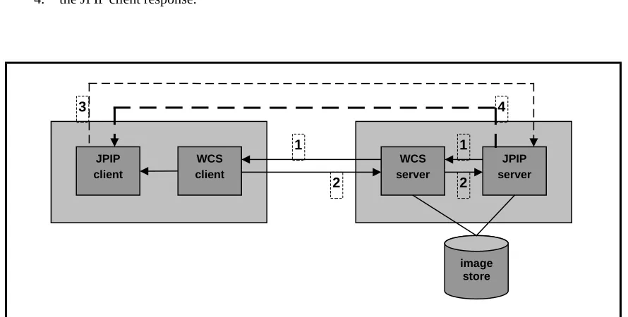
The general coverage request process consists of four parts (Figure 1):1. the coverage server request, 2. the coverage server response, 3. the JPIP server request, and 4. the JPIP client response.
Figure 1 – WCS/JPIP Architecture
6.2
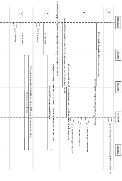
Walk-Through of the Full Protocol
To describe the WCS/JPIP interaction in detail, we now provide a detailed example of a viewing client application with which the user will request some scene.
JPIP client
WCS client
WCS server
JPIP server
image store
1 1
2 2
We will make the following assumptions:
There is a viewer application which contains three modules: a viewer engine, a JPIP client, and a WCS client.
The WCS server and the JPIP server are separate servers on different machines.
The URL for the JPIP service is http://jpip.example.com:101/jserv. That is, the host name is jpip.example.com, the port number is 101, and the actual service name is
/jserv.
The resource named dir/chicago.jp2 is known to the JPIP server.
6.2.1 Protocol Part A – Configuration
6.2.1.1
Step 0
The administrator adds the dir/chicago.jp2 file to the WCS server using the coverage-id
ChicagoData. In doing so, the administrator enters the JPIP service URL (host name, port number, service name) and the resource identifier to be associated with the coverage-id.
NOTE: This step is implementation dependent; it is not within the scope of the WCS specification.
6.2.2 Protocol Part B – WCS Request and Response
6.2.2.1
Step 1
The viewer engine wishes to display a scene from the ChicagoData coverage. The coverage-id and the bounding box of the scene, in geographic coordinates, are passed to the WCS client.
6.2.2.2
Step 2
The WCS client issues a GetCoverage request to the WCS server, using the coverage-id and bbox that it just received. The output format MIME type indicates the response should be a “JPIP redirection response document”.
Example of WCS client GetCoverage request (newlines added for clarity):
SERVICE=WCS&
[Note the double quoting in the FORMAT parameter. Can that be fixed? -mpg]
6.2.2.3
Step 3
The WCS server uses its own internal tables to determine the resource id for the given coverage id and bbox.
NOTE: In general, this may correspond to multiple resource ids; we only deal with the single case for now.
6.2.2.4
Step 4
The WCS server performs the transform function to compute the image coordinates of the target image for the given geographic bounding box. This is expressed as an offset (roff) and a size (rsiz).
NOTE: In general, this may correspond to multiple offsets and sizes; we only deal with the single case for now.
6.2.2.5
Step 5
The WCS server uses its own internal tables to determine the JPIP host name, port number, and service name for the coverage-id and bbox.
6.2.2.6
Step 6
The WCS server issues a response to the WCS client. This JPIP response document contains the following information:
target-name (e.g. dir/chicago.jp2)
JPIP service URL, expressed as host name, port number, and service name
rsiz and roff values, which are the actual dimensions of the image and its upper-left position
JPIP transport (e.g. http)
The encoding of this document is a simple sequence of key-value pairs. Example of JPIP response document:
document-version=1.0.0
Note that these key-value pairs correspond exactly to the syntax used within the JPIP protocol. In the event that multiple targets are to be returned, the document should contain all parameters for the first target, followed by all parameters of the second target, and so on; parameters from different targets must appear in target order and may not be intermixed. The order of the targets defines the Z-order of the images; that is, the image of the first target is the “bottom” layer and may be occluded by the images of subsequent targets. Lines beginning with “#” should be interpreted as comments, used only for debugging and diagnostics.
6.2.2.7
Step 7
The WCS client receives the WCS server response and passes the response document data to the viewer engine.
6.2.3 Protocol Part C – JPIP Request and Response
6.2.3.1
Step 8
The viewer engine computes the frame size (fsiz) needed to satisfy the user’s request; this essentially corresponds to the resolution desired. The viewer engine now has the information it needs to establish a JPIP session and request image data. It passes the following information to the JPIP client:
target-name (e.g. dir/chicago.jp2)
JPIP service URL, expressed as host name, port number, and service name
rsiz and roff values
JPIP transport (e.g. http)
fsiz value
NOTE: a future version of this specification should give the client the (optional) ability to specify the JPIP rounding control method as well.
6.2.3.2
Step 9
target-name (e.g. dir/chicago.jp2)
rsiz and roff values
cnew parameter (set to http, requesting a channel-id be issued)
len parameter (set to a “download chunk” size of 2000)
stream parameter (set to 0, indicating the first codestream is to be used)
type parameter (set to jpp-stream, indicating that precinct bins are to be used)
fsiz values
tid parameter (set to 0, to request the actual target-id be returned from the server)
cid parameter (set to 0, to request the actual channel-id be returned from the server)
NOTE: some of these parameters, e.g. len, are optional and are provided only for pedagogical porpoises.
Example of JPIP client request (newlines added for clarity):
GET /jserv?
The JPIP client may wish to initially omit the scene coordinates, so that it can just retrieve any metadata from the image. The scene request can then later be made as in Step 13.
6.2.3.3
Step 10
The JPIP server responds to the JPIP client with the assigned channel-id (8558206) and the requested compressed image data, up to the 2000 byte limit. The target-id is also returned.
Example of JPIP server response:
HTTP/1.1 OK JPIP-tid: …
JPIP-cnew: cid=8558206 …
(2000 bytes of binary data)
6.2.3.4
Step 11
6.2.3.5
Step 12
The viewer engine receives the raw image data and renders it to the screen.
6.2.4 Protocol Part D – Further JPIP Requests and Responses
6.2.4.1
Step 13
Assuming the JPIP client has not yet received an EOR response, indicating no more compressed image data is available, the client issues another request to the JPIP service. The data passed is the same as in Step 9, with the single exception that instead of passing the cnew parameter, the cid value (8558206) is passed to indicate an already-open channel.
6.2.4.2
Step 14
The JPIP server responds to the JPIP client with the requested compressed image data. (This is the same as Step 10, except that no channel-id is returned.)
6.2.4.3
Step 15
The JPIP client receives the compressed image data. It performs the jp2 decoding operation and passes the raw image data to the viewer engine. (This is the same as Step 11.)
6.2.4.4
Step 16
The viewer engine receives the raw image data and renders it to the screen. (This is the same as Step 12.)
6.3
Protocol Discussion
6.3.1 Subsequent Scene Requests
As the viewing application requests additional scenes from the same coverage id and resource id, the Part D sequence (Steps 13 through 16) may be repeated.
6.3.2 Multiple Files in a Single Coverage
As noted in the Part B sequence, a given geographic bounding box may correspond to multiple files, even within a single coverage. If so, the response document in Step 6 will contain multiple sets of information and will entail multiple iterations of Part C.
In this case, each new scene request (such as from a pan operation) could potentially touch one or more new files. To be safe, a WCS request should first be made with the new geographic bounding box in order to get the correspond filenames. However, this approach in general would lead to a WCS query and response for every new scene touched. There are three possible implementation techniques to address this. First, a client may prefer to make its first WCS request an overview of the entire coverage, using the known bounding box extents of the coverage. (This will be a common workflow: for example, consider the case where the viewer first needs a low-resolution overview of the area of interest.) The WCS response will include all the filenames in the coverage and their bounding boxes; the client will then not require any further WCS interactions for that coverage.
A third approach would be to address the problem on the server side by making the server responsible for dynamically mosaicking the files in question into a new JP2 image, so as to only require the return of a single, “temporary” filename.
6.3.3 Band Support
The band axes in the CoverageRequest are mapped to the components in the JP2 image, i.e. the
comps JPIP request parameter. (This is not reflected in our discussion above.)
6.3.4 Codestream Selection
A CoverageOffering supports a rangeSet element, which defines the properties (categories, measures, or values) assigned to a geographic domain. The JPIP codestream request parameter is used to identify which codestream(s) belong to the requested view window. If the field is omitted and the codestream(s) cannot be determined by other means, the default is the single codestream with identifier 0.
By integrating JPIP and WCS we are mapping a JPIP view window onto a geographic subset, making it possible to map a codestream identifier to a rangeSet category called codestream. If the codestream request is omitted this defaults to 0, the first codestream.
6.3.5 Metadata
In section 3.6 above, we discuss our approach to handling metadata in the image, i.e. ancillary JP2 boxes. This JPIP architecture maintains the same general approach, in that proper metadata is assumed to be available via WFS or similar means. Within the bounds of the JPIP protocol, however, note that the JPIP client is responsible for actually requesting and downloading what boxes are available.
6.4
Impact of Client/Server and Server/Server Interfaces
The model described above presents an abstract implementation of the WCS/JPIP system. In particular, only the WCS interfaces are mandated by this standard. A simple implementation of the system would keep the JPIP server and JPIP client somewhat separate from the WCS server and WCS client, possibly allowing for the use of a stand-alone, third-party JPIP server.
To reiterate: this standard only defines the WCS request and response syntax for setting up and controlling the JPIP communications link, and implicitly entails the use of a separate channel for formal JPIP
communications.
6.4.1 Cascading Servers
As discussed, the architecture cleanly separates the WCS server from the JPIP server; there is nothing to prevent the two servers from being hosted on different machines. The WCS server need only maintain the address of the JPIP server (and associated file and coverage information).
This design has two useful side-effects. First, separating the WCS and JPIP servers allows for better use of hardware resources, e.g. in terms of hardware configuration or geographic dispersion. Second, a clever WCS/JPIP system might take advantage of the inherent “redirection” going on to achieve better load-balancing by having the “main” JPIP server apportion incoming requests out to multiple JPIP servers.
6.5
Formats for the Response Document
This protocol above shows the JPIP response document to be a KVP-encoded text document. It would be preferable to replace that with an XML document, such as the following:
<jrd:JpipResponse version="1.0.0"> <jrd:JpipTarget>
<jrd:host>jpip.example.com</jrd:host> <jrd:port>101</jrd:port>
<jrd:path>/jserv</jrd:path> <jrd:rsiz>831,822<jrd:rsiz> <jrd:roff>0,0</jrd:roff>
<jrd:transport>http</jrd:transport> </jrd:JpipTarget>
</jrd:JpipResponse>
Note that multiple targets (see Section 6.2.2.6) can easily be supported with this format.
[Still need to provide an actual XML schema for this, including the “JpipResponseDocument” (jrd) namespace. –mpg]
7.
File Format and Data Model Mapping
Everything in Section 6.1 and 6.2 of 07-145 (WCS application profile for JPEG 2000) applies to this WCS application profile for JPIP.
Additionally, should mention that this specification mandates nothing about the use of JPP-streams versus JPT-streams.
8.
Examples
tbd9.
Reference Software
We are aware of two WCS implementations which conform to some or all of this application profile.
ITT IAS – http://www.ittvis.com/ias/index.asp
LizardTech Express Server – http://www.lizardtech.com
10.
Compliance Testing
[tbd. I’ve no idea what this section is supposed to contain. –mpg]