Connection System Between Column and Beam
for Simple House
Sentosa Limanto
Department of Civil and Planning Engineering, Universitas Kristen Petra, Surabaya, Indonesia
Johanes I. Suwono
Department of Civil and Planning Engineering, Universitas Kristen Petra, Surabaya, Indonesia
Abstract:
Precast concrete connections systems have various designs and function of each, and not all of the connections that are required to fulfill the same working criteria. The dimension of building prototype is 2 m x 2 m x 2 m, the function of connections is to unify the elements of construction‟s structure to be a monolithic unity, so that can seek the stability of construction‟s structure. The use of prefabricated concrete allows good quality control and fast construction method. For the manufacture of small houses this method of constructuon is very promising. The connection system of columns and upper tie beams is always simple connection. To know the reliability of this connection system, the prototype of building frame was build, and a differential settlement applied, with a deflection up to two precentage its length, the tie beam experienced cracks but the connection remained intact and the instalation time of the components are assembled into a single unit structure, is 340 minutes.Keywords
:Building prototype, Connection system, Prefabricated concrete, Simple house1 INTRODUCTION Consctruction Materials
Concrete is a construction materials which is widely used in Indonesia, if is compared with other materials because the forming materials are easily obtained in Indonesia, durable enough, and the price is relatively affordable. Some aspects that could be a concern in conventional concrete systems are the long implementation time, a lot of waste material which is produced, the quality control which is difficult to be increased and also the mold base materials of wood and plywood that are increasingly expensive. Precast concrete system is a construction method that is able to respond the needs in this era which requires a fast and effective of the construction. This precast concrete is made in the fabrication place which the quality will be controlled, the finished concrete is brought to the location directly to be arranged into a unified whole structure. Precast concrete connections have various designs and function of each, and not all of the connections that are required to fulfill the same working criteria. The building prototype of structure connections (2x2x2 m3) also function to unify the elements of construction‟s structure to be a monolithic unity, so that can seek the stability of construction‟s structure. In the process of installation of column and beam of precast is needed the installation time for 340 minutes with this precast column and beam can save
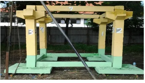
the time compared with this conventional installation time can be accelerated with the making process of precast column and beam in the factory where all of the sizes have the same precision with the existing connections and the quality of concrete can be controlled (Figure1.)
Figure 1. Prototype of column and beam connection
1.1 Type Connection
The types of connection which are usually used between precast component:
analysis and computer modeling because between building structural elements can behave not monolithic.
Wet connection. Wet connection consists of the discharge of steel reinforcement from the end of the precast concrete components which between that reinforcement is connected with the help of mechanical joint, mechanical coupled, splice sleeveor the length of distribution. Then, on that connection part is done the casting of concrete in place. This type of connection can function well for reducing the adding of stress because of creep, decreasing and temperature changes. This wet connection is highly recommended for buildings in the earthquake prone areas because it can make each components of the precast concrete to be monolithic.
1.2 Green Living Construction.
Precast concrete construction is widely used in construction because it can work fast, proper, and efficient. This system is very efficient if is applied in the construction of the simple house. This precast concrete system is green living, because it does not cause the waste of the rest of the construction, and the quality of concrete can be controlled by the factory. This study focuses on how the relation between pedestal structure and column, and column with the beam up so that allow to remain stable with a relatively short duration of work process. From the result of this study is expected that in the working process of column and beam from a simple house building, will be much faster and green living. It is faster because the making of column and beam is using the precastsystem, which can save the time and the cost in a construction project. Besides that, the connection system can be applied to the housing industry which is growing in Indonesia, especially in Surabaya.
1.3 Pedastal-Sloof Connection and Column
The connection between pedestal and columns is using the pedestal design by giving a hole to stand in a column (Limanto S., et. al., 2013). The researchers are continuing the pedestal design that has been given a hole and it is named coakan which can be idealized the connection between pedestal and column is the joints where it can receive only vertical and horizontal force. Horizontal force is 10% of vertical force and maximum vertical force is 3,000 kg/coulumn (Limanto Sentosa et. al., 2013).
.
1.4 The Connection between Column and Beam
The design that the researchers will use is taken from the book of Connection For Precast Prestressed Concrete Building(Martin and Korkosz, 1982) which was published by PCI. The researchers took this design because this design is simple, can be done directly in the field, and does not require experts. In this type is needed a console that is given a shaped box and it will be used for the entry of hole that is prominent from the side of the beam. The force which is received by the beam will be channeled to the console. To strengthen this connection, the researchers will utilize the wet connection system in the form of grout. The advantage of this connection is easy and fast in installing, fewer problems in installing, providing shear resistance and some torque controlling after grouting. The disadvantage is there is no lateral connection until the hole is filled in with grout, no capacity moment, the hole in the beam can be filled with water if there is no prevention.
Figure 2. Pedastal-Column and Beam Connection
2 CONNECTION TYPE ANALISYS 2.1 The Selecting of the Connection Type
Three-dimensional images of Pedastal-Column and Beam Connection (Figure 2.). Apply the selection of this design is simple, can be done directly in the field, and does not require experts. The force which is received by the beam will be channeled to the console , therefore, the console must be strengthened with reinforcement which is inserted to the column so that the column is safe (Henderson, Albert, 1951).
in the console needs to be considered carefully because the console is an important part in this connection system that supports the four existing beams. Here the size dimensions of each beam and column: the column has dimensions of 20 x 20 cm² with the height 200 cm and the beam has dimensions 10 x 20 cm² with the length 200 cm (Johan and Eddy F, 2013).
2.2 The Installation of the Connection System
After the formwork components (column and beam) have been removed, the next step is the installation of each component into a single unit structure. The steps which need to be done in the installation of the components in this study are:
a) The cleaning of the green field land near the components is to install a pulley on a tripod, after that the tripod is being stood up and is slid to fit on the center point of the pedestal.
d) The fastening of the column with the chain pulley at the bottom of the console‟s column strongly and is tightened for safety.
e) The slowly withdrawal to the up of the column, while the bottom of the column is given a rope in order not to damage the connection of the column‟s bottom to the pedestal.
f) After the column is setting up straight just above the pedestal, then the pulley is being lowered slowly. Previously is done the flattening on the top of the pedestal from the previous study and the alignment column is perforated so that the column sets upright in the pedestal. Doing the nudge of the column with water pass; if it is still not in the right angle, will be done a perforate again between pedestal‟s column or column sets upright.
g) After the column is connected to the pedestal, the next step is the giving of scaffolding on the right and left side of the column so that the column is not inclined to the right and left.
e) After the column is setting up, then it will continue the process of setting up other columns with the same steps.
The installation of the beam is done after the two columns are set up by binding the pulley rope on the center of the beam and then the withdrawal of the rope on both left and right ends of the beam in order not to damage the existing connectiond.
2.3 The Testing of the Effect of Differential Settlement To find out whether the connection system of pedestal-column and column-beam is already stable, then is conducted the testing of differential settlement where the foundation is made as down according to circumstances that may occur in simple homes with a reduction can affect various components that are exists in a building. In this study, the researchers are examining the parts of the connection whether it occur a crack or not if there is a decrease at one point of the foundation. The steps of the testing are as follows:
a) The checking of the condition of the building, and
d) Measuring the height of each pile cap that has been installed.
e) Lifting the pile cap as high as 1-2 cm.
f) Observing what happens to all of connections that exist.
g) The rafter 5/7 on the left side of pile cap is rotated if the pile cap is wedged with the rafter with a height of 7 cm, now being 5 cm.
h) The pulley is lowered slowly until the left part of the pile cap is going down to the bottom, is done the observation of all of the connections that are exist.
i) The chain in the left part is removed and is moved to the right column which is used to rotate the right part of the beam.
j) The pile cap is raised as high as 0.5 – 1 cm.
k) The right part of the wooden beam is being rotated.
l) hecking and documenting on the physical condition of the building after the building is being tested.
n) The right part of the pile cap is reappointed in order to do the turning of the beam to the home position.
o) Releasing the chain and move it to the left part of the column to lift the left part of the pile cap and rotate the beam.
p) The beam is rotated to the home position and the chain is being released.
q) Summarizing the tripod and pulley which have been used.
3 DISCUSSION AND ANALYSIS
The weight of each component is the column with the weight 290,4 kg and the beam with the weight of 88,8 kg ( Johan and Eddy F., 2013)
a) After the formwork is released, all of the components are assembled into a single unit structure and the workforces are using three prentices and machine pulley in the installation, instalation time is 340 minutes.
b) The result of the strength of the cylinder testing after 28 days: strength σ„= 130.05 kg/cm²
c) From the testing of the effect of the differential settlement is obtained the decreasing that is permitted so that the structure remains stable 1/100 from the L sloof (the length of sloof) and the maximum decrease which happens until the structure is not stable is 1/50 from the L sloof (the length of sloof).
4 CONCLUSIONS
From the observations which are obtained either from the literature review and data analysis, the conclusion is as follows:
a) The sample of column and beam which is installed as planned, can be concluded that the structure is stable and if there is a decrease of 2 cm or 1/100 x Length of sloof (= 200 cm) then the structure is stable and the connections are still intact.
b) In the process of installation of column and beam of precast is needed the installation time abaut 340 minutes (Figure 3.)
Figure 3. Pedastal-Sloof-Column Connection
REFERENCES
Henderson, Albert. (1951). Patent No.2,569,669
1951.Pittsburgh,pa.
http://en.wikipedia.org/wiki/Google_Patent_Search
Johan and Eddy F., (2013). “Pekerjaan Sambungan Beton Pracetak Antara Struktur Pedestal, Kolom Dan Balok Atas Untuk Rumah Sederhana”. Undergraduate thesis, Civil Engineering Departement, Petra Christian University Surabaya, 2013.
Limanto S., Indrojono J. S., Wuisan R., T., and Raharjo, C. (2013). “Konstruksi Pondasi Tapak dan Sloof Pada Struktur Bawah Rumah Sederhana Satu Lantai”. KoNTekS 7 UNS Solo, Indonesia.
Limanto Sentosa, Indrojono J. S., Prakoso R., and Sejo, A. L., (2013). “Sistem Sambungan Pada Pondasi Tapak Beton Bertulang”. Konfrensi Nasional Pasca Teknik Sipil 3 ITB, Bandung, Indonesia.