An interaction framework for VR and AR applications
M. Scarpa
R.G. Belleman
Section Computational Science
University of Amsterdam
{
mscarpa
|
robbel
}
@science.uva.nl
Keywords:Virtual Reality, Augmented Reality, UIMS, human computer interaction
Abstract
The implementation of interaction techniques in Virtual Reality (VR) and Augmented Reality (AR) applications still poses a considerable challenge for
developers. There are few tools, conventions and
standards to rely on. This paper presents the design of a framework aimed at the separation of interaction-specific and domain-interaction-specific functionality of VR/AR applications. The goal is to alleviate the develop-ment of interaction techniques by providing generic, re-usable components.
1
Introduction
Interaction paradigms for VR and AR have not un-dergone a comparable process of standardization that resulted in today’s common WIMP paradigm and the standard user interface (UI) elements for the desktop [1]. One explanation for this is the highly heteroge-neous nature of VR and AR setups.
As a consequence, there is a high degree of in-compatibility between the various setups. VR/AR ap-plications are therefore designed and developed with one particular setup in mind and are rarely ported to another. This is sometimes due to the high costs of adjusting the code to the differences between setups. Additionally, different environments present some-times radical differences in the interaction possibili-ties offered to the end user, which introduces incom-patibilities in the operation of the system next to in-compatibilities in the application code.
This paper proposes a framework that aims at sep-arating the domain-specific functionality of a VR/AR application from the interaction-specific functionality. It introduces an additional layer that handles all input data from the user. The obtained data is processed in a bipartite data-flow network made of components that together implement the interaction.
2
Related Work
The separation of interaction-specific and domain-specific functionality has been advocated in the work related to User Interface Management
Sys-tems (UIMS) [2]. A UIMS mediates the
interac-tion between the user and an applicainterac-tion by satisfy-ing requests from both user and application. This is achieved through a three-tiered model: the lowest level isolates physical devices, which are then man-aged in the middle layer as logical devices. On the top level, an interaction management system contains descriptions of the dialogue sequences that describe the interaction between user and application [2].
Research on UIMS has been extensive. Among the more closely related work is that of Jacob et al. [3], in which state diagrams and Petri-nets are used to model interaction in VR environments. In [4] the develop-ment and adaptation of reality-based interfaces based on the token and constraint paradigm [5] is discussed. The author advocates dynamically changing execu-tion environments and concurrent interacexecu-tion across various devices.
Another direction is explored in [6], in which users of ubiquitous AR systems are allowed to adapt the system to their preferences using a concept called “in-teraction management”. Similarly, Jacob addresses the runtime adjustment of the interface between UI and application to improve accessibility [7].
In the Alpha UIMS the separation between interaction-specific and domain-specific functionality is supported but not enforced by a component-based design, in which different “agents” communicate with each other, implementing various parts of the applica-tion [8]. These agents are organized through a “di-alogue”, specified using a separate language called “slang”.
wherein concrete interaction objects are abstracted into counterparts that capture only generic features. This approach allows no run-time adaptation and is aimed at the evaluation of virtual user interfaces.
Navarre et al. developed a formal description for interaction in virtual environments that addresses the variety of available input devices [10].
2.1
Scope of this work
This paper addresses several issues where the re-lated work falls short, as described next.
Meyers et al. identify two reasons for the lack of success of UIMS [1]. First of all, the often strict separation between interaction-specific and domain-specific functionality has often been perceived as a hindrance rather than an aid to the design and im-plementation tasks. Secondly, UIMS were originally aimed at resolving the issues of user interface design for the emerging desktop systems, but through the standardization of the user interface elements in that environment, the need for UIMS disappeared. It is unlikely that a similar standardization of user inter-face elements will occur in VR/AR, which warrants the renewed investigation into UIMS for VR/AR ap-plications.
Many interaction techniques exist in VR/AR today, both for generic as well as for very specific tasks [11]. Unfortunately, very little approaches exist that ab-stract them into generic, re-usable components. Most of the techniques available today are implemented as part of more complex applications that are tied to par-ticular hardware configurations. The abstraction of interaction techniques into generic, re-usable compo-nents not only allows the creation of a whole library of interaction techniques [12, 13], but also a way to eas-ily replace one technique with another. This makes it possible to easily replace techniques unsuitable for a given setup, as well as to compare and evaluate the use of different techniques in a particular scenario. Additionally, it allows the users to specify preferences about which techniques they want to use.
Additionally, specific interaction techniques can be tightly related to a particular domain, rendering it much more difficult – and maybe even
counter-intuitive – to generalize them. Such interaction
techniques might take harm from a separation from the domain-specific functionality instead of profiting from it. The application developer should be able to decide which functionality is domain-specific and which is not, effectively allowing for the framework to adjust to the developer instead of forcing the re-verse.
Interaction in VR and AR applications comprises both discrete and continuous, sequential and concur-rent events [3]. Most approaches found in literature cope with this difference by using two separate
mod-els, such as Petri-nets for the continuous aspects and state diagrams for the discrete aspects [3]. The use of two different models introduces additional complex-ity in the description of interaction, which makes the adoption of such systems difficult.
In [14] the authors point out that there are indi-rectly related aspects that may be significant for the performance of interaction techniques. Especially the feedback of the system is important for the successful use of interaction techniques. This stands in contrast with the general concept of strictly separating input and output functionality, as advocated by many UIMS implementations.
3
Architecture
The proposed architecture consists of a framework that allows the application developer to “request” in-teraction capabilities for the end user, e.g. “the user must be able to change the position of this object”. When the application is deployed, the framework must accommodate all the requests of the application. To achieve this, a data-flow network is constructed, such that the requested functionality can be obtained. The data-flow network consists of various objects and sub-nets that are taken (possibly automatically) from a predefined library or provided by the application de-veloper – or even the maintainer of the system.
The following sections describe the elements of the proposed framework architecture in more detail.
3.1
Data Representation
All data processed by the components of the data-flow network is represented by subclasses of the
ab-stract class Value. This class defines only the most
basic requirements for aValueobject:
name A human-readable string describing this value.
The purpose is to add semantic information to the value, such that a user can understand what this value represents. For example, the object representing the vertical position of a mouse pointer would be called “vertical mouse posi-tion”.
value The actual value. This is undefined in the ab-stract class.
compatibility operator Verifies if twoValueobjects are semantically compatible.
The compatibility of twoValueobjects is defined
0.5]. Furthermore, two lists ofValueobjects are de-fined as being compatible if every element with index
iof the first list is compatible with the corresponding
element at indexiin the second list.
Concrete subclasses of theValueclass are expected
to extend the abstract base class adding any attributes necessary to properly characterize the value repre-sented. This characterization is important to assert the compatibility of the values generated by one com-ponent and required by another comcom-ponent. The at-tributes of a value are stored together with the actual data in order to allow access to these attributes any-time during the processing of the data.
3.2
Data-flow Network
The whole process of interaction is modeled using a data-flow network that represents the flow of data from (logical) input devices to either interaction tech-nique components or call-back functions of the appli-cation. This approach was chosen, because this con-cept is widely used in many tool kits and is therefore familiar to many developers. The data-flow is orga-nized in a directed, bipartite graph consisting of two
classes of objects:processing objectsandconnection
objects.
Processing objects represent any kind of operation that uses data as input and/or output. Every logical input device or interaction component is represented as a special processing object in the data-flow graph. This class of objects is characterized by the following features:
identifier The identifier describes the functionality
of the object. For components implementing
interaction techniques, this identifier specifies what interaction is implemented. This is used when the requirements of an application are matched with the elements of the data-flow net-work. For input devices, this identifier specifies that the object is an input device.
input signature The input signature specifies a list of inputs required by this object. Every item in this list is semantically seen as one single input,
which can either be aValue object or a list of
Valueobjects. The order of the elements in the input signature describes the order in which the data has to be provided to the execute method (described shortly).
output signature The output signature specifies what outputs the technique provides. It is repre-sented in the same fashion as the input signature.
execute method This method causes the execution of the functionality of this object. It takes as ar-gument a list as defined by the input signature and computes a list consisting of the values as
specified by the output signature. These values can then be accessed using the output retrieval method.
output retrieval method This method returns either a list of values matching the output signature
specification or NIL, if no output is available.
This distinction is crucial, because a connection object will only transfer data from its sources to its destinations if all the sources are able to provide data. For convenience reasons, a second output retrieval method could be added, that only returns specified outputs instead of returning all of them.
Connection objects manage the flow of data be-tween processing objects. A connection object reads data from one or more processing objects and for-wards this data to the execution method of one or
more processing objects. The following attributes
characterize a connection object:
sources A list of processing objects from which the connection object reads data using their output retrieval method. The processing objects that provide data to a connection object are called the “sources” of the connection object.
destinations A list of processing objects to which the connection object passes the read data call-ing their execution methods. The processcall-ing ob-jects that receive data from a connection object are called the “destinations” of the connection object.
mapping The mapping defines how the outputs of the sources are mapped onto the inputs of the destinations. Every output of all sources is re-lated to zero or more inputs of all destinations. A mapping is not required to be either injective nor surjective: inputs from any source can be re-layed to one or more destinations, or none at all. This is useful e.g. for the conversion of discrete to continuous events (see Section 3.6).
Please note that the data passed through by a con-nection object is in no way modified by the connec-tion object. Data is only processed by a processing object. If the output of a processing object is not com-patible with the required input of another processing object, they cannot be connected directly through a connection object. Also, a connection object does not perform any kind of buffering. If such functionality is required, special processing objects that implement it must be used.
3.3
Logical Input Devices
There are various subclasses of processing objects,
derived from the abstract classPObject. Physical
are represented by subclasses of theDeviceclass, an
abstract subclass of thePObjectclass. This approach
has been chosen to offer an easy means of extending the range of supported devices. To add support for a new device, it is sufficient to create a new subclass of the Device class that implements the necessary driver-calls. By creating implementations that sup-port hardware-abstraction libraries like VRPN [15], a wide range of devices can easily be added to the list of supported hardware.
The abstractDeviceclass does not extend the
func-tionality of the abstractPObject class. Its existence
is purely semantic, to group all logical device imple-mentations in a separate branch of the class hierarchy. The input signature of such objects is usually empty, since instances of this class are supposed to provide data from the actual hardware they represent. The out-put signature, instead, provides the data. It is impor-tant to note that the way a device presents its data is ambiguous. A six degree of freedom tracking device can present its data as a list of six separate values, as only one tuple (consisting of six values), as two tuples (e.g. each containing three value), etc. It is though advisable to adopt a convention for the way devices present their data to the framework. Such a conven-tion can be used to enforce certain aspects onto the networks created, allowing the quantitative distinc-tion between analogous network configuradistinc-tions (see discussion in Section 5).
3.4
Interaction Techniques
Another group of subclasses of thePObjectclass
are those implementing basic interaction techniques, like selection and manipulation.
Using a data-flow network to represent the inter-action allows to represent complex interinter-action
tech-niques as sub-nets of more basic techtech-niques.
In-teraction techniques are often categorized using tax-onomies, whereby tasks are divided into multiple sub-tasks [14, 11]. This structure can be entirely repsented in the data-flow network, enhancing the re-usability of the sub-components of a complex interac-tion technique and facilitating the design of new, com-plex techniques. The composition of comcom-plex tech-niques is discussed in more detail in Section 4.3.
3.5
Callback Functions
To give the application developer free choice about how to implement specific functionality, the presented framework offers the possibility to register callback functions that are called by special processing objects in the data-flow graph. In this case, the application specifies a callback function and an input signature. A special processing object is then instantiated, that takes over the specified input signature and passes the input data it receives to the given callback function.
3.6
Discrete and Continuous, Sequential
and Concurrent Events
In [3] the authors highlight that interaction in VR/AR applications often comprises both discrete and continuous events, sequential or concurrent. The proposed model supports all these modalities through the special characteristics of the connection objects. Connection objects always pass their input data to their destination processing objects – if the data is
available. This models continuous events, in the
case that all the sources of the connection object are continuously providing data. Alternatively, discrete events are achieved, if at least one of the sources only provides data at discrete moments in time.
The modeling of interaction in a data-flow network also supports the description of concurrent events, as there is no limitation to how many separate paths the network can contain. One instance can be made of an arbitrary number of sub-graphs.
3.7
Feedback to the User
In order to ensure usability, interaction techniques must provide sufficient feedback to the user. The ef-fects of user interaction should be reflected in the state of the application with as little delay as possible. To allow this, the presented architecture offers process-ing objects access to the application’s scene graph. Special processing objects that provide lists of scene-graph objects can be made available e.g. by the appli-cation. This enables not only the complete implemen-tation of an interaction technique outside the applica-tion itself, but it also allows interacapplica-tion techniques to directly influence objects seen by the user, providing immediate feedback.
3.8
Graph Representation
The composition of interaction techniques and the arrangement of data-flow graphs can be expressed both programmatically using the provided API, but it can also be represented graphically as a directed, bi-partite graph. This has the advantage that a developer can define the interaction-specific functionality that is not provided directly by the framework in the same fashion as the rest of the application. Alternatively, end users can adjust the interaction network easily to match their preferences using a visual editor to edit the data-flow graph.
experi-enced users can also edit the data-flow graph directly, using a visual editor.
3.9
Network Execution Model
For the execution of a given data-flow network, a notification mechanism is introduced. A processing object sends a notification to all connection objects reading from it, signaling the availability of data. Ev-ery connection object maintains a status array describ-ing the availability of data for each of its sources. Whenever a notification arrives, the connection ob-ject marks the corresponding field in the status array as true. Only if all fields are true, it resets the array and passes on the data.
4
Implementing User Interaction
This section discusses the implementation of user interaction techniques using the proposed framework.
4.1
Notation Conventions and Basic
Constructs
The easiest way to represent the described data-flow networks is through diagrams. In the following sections, the data-flow network examples discussed will be represented graphically as bipartite, directed graphs. Processing objects will be represented by ovals, while connection objects will be represented as thin rectangles. The text inside an oval describes the type (between pointy brackets) and/or the name of the object (between double quotes). An excep-tion to this rule is made for “condiexcep-tional filters” (see Section 4.1.1). The text inside ovals depicting these objects represents the condition under which the re-ceived data is forwarded. A connection object’s map-ping is represented graphically through the vertical correspondence of inbound and outbound arrows.
The following sections discuss some basic con-structs often used in data-flow networks as presented here.
4.1.1 Conditional Connections
It can be useful to create connections between pro-cessing objects such that they are only active under certain conditions. To achieve this, special processing objects called “conditional filters” are used in com-bination with the particular characteristics of connec-tion objects.
Conditional filters are special processing objects that take a given input and test it on a given condition. Only if the condition is met, the input is passed on as output. Adding such an object to the sources of a given connection object results in stalling the connec-tion as long as the condiconnec-tion of the condiconnec-tional filter is not met – even if all other inputs are available.
4.1.2 State Transitions
Interaction techniques often distinguish different states. Depending of the current state, the actions of the user have different meanings. In terms of the presented data-flow networks, states are used to ac-tivate and deacac-tivate certain connections. To model this, another special processing object type is used: “buffers”.
Buffers are special processing objects that remem-ber the last received input and provide it continuously as output. Using a buffer object as the state variable, it is possible to implement state-persistence. Further-more, connecting a buffer to a conditional filter can be used to render connections active only for certain states.
4.1.3 Event Conversion
Discrete events can easily be converted to continuous events using a buffering objects to remember the last data obtained and output it continuously. In similar fashion, continuous events can be converted into dis-crete events in two ways. The first option is to use conditional filters to restrict the continuous output. The second option is to use the characteristic of a con-nection object to only forward data once all its sources have data available. This way, the continuous output is blocked until another, discrete output is available.
4.2
Examples
The following sections present some examples for the implementation of common interaction techniques using the proposed framework.
4.2.1 Pointing Selection with a Wand
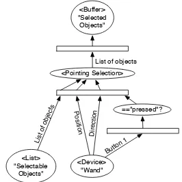
A wand consists of a 6DoF tracker with some buttons attached. One of the most popular class of selection techniques used in conjunction with a wand is “point-ing selection”: a virtual ray extends from the front tip of the wand and objects intersecting with this ray are selected when the user presses a button.
To model this behaviour in a data-flow network, the wand is represented as a logical device from a
subclass of the Deviceclass. This object must
pro-vide the position and orientation of the wand, as well as the state of all the attached buttons.
Another component must implement the selection mechanism itself. This component requires three in-puts: a position from where the ray is cast, a direction into which the ray is projected and a list of objects that can be selected. Using this data, it is possible to com-pute ray-intersection with all selectable objects and thus produce a new list of selected objects.
position and orientation of the tracker, as well as the state of all the buttons. Yet, the actual “act” of select-ing an object is a discrete event that happens when the user presses a certain button. To model this, the continuous status-report of the button are converted into discrete events. This is achieved using a condi-tional filter. In this case, the criterion is that the status of the button must be “pressed”, syntactically defined through a symbolic constant.
Finally, a selection should be persistent, until the user changes the selection (e.g. selecting another ob-ject, or “de-selecting” through a selection of “noth-ing”). A buffering object is used to store the results of the selection. Figure 1 displays the resulting data-flow network.
<Buffer> "Selected Objects"
<Pointing Selection>
<Device> "Wand" <List>
"Selectable Objects"
=="pressed"?
D ire ctio
n
Po si
tion
List of
obje cts
Butto
n 1
List of objects
Figure 1: Pointing selection with a wand.
4.2.2 Complex Example: Positioning using a Data-glove
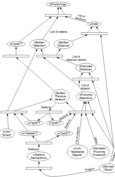
This example discusses a common interaction tech-nique used in combination with a data-glove input de-vice. The user selects a virtual object by “grabbing” it. The selected object will remain selected as long as the gesture is retained. As long as the object is selected, its position relative to the data-glove is pre-served: the user moves the object by moving the hand wearing the glove. Please note that for the sake of brevity, rotation is left out in this example, although it could easily be added, as described at the end of this section.
The described interaction can be decomposed into three parts: first, the selection is determined; second, the relative position of the object in respect to the data-glove is calculated upon selection; finally, the object is moved as long as the object is selected.
An object is selected if it is within a given thresh-old from the glove’s position when the user performs the gesture “grabbing”. It would be a mistake to sim-ply couple the proximity calculation to this gesture recognition, because the selection should only occur once. As soon as an object is selected, the interaction
paradigms change: movement of the glove is reflected in movement of the selected object, while approach-ing another object must not result in the selection of that object as well.
To achieve this, a state-transition is introduced. When the gesture performed by the user changes from “not grabbing” to “grabbing”, the state changes from “nothing selected” to “selection made”. This re-flects the conflictual nature of continuous and discrete events: a gesture is a continuous characteristic of the data-glove, while the transition from one particular gesture to another is a discrete event.
In addition to the discrete event of selection, there is another discrete event caused by the user “releas-ing” the selected object. For the sake of argument we shall say that the user signifies the end of the operation with a particular “release” gesture. If and only if the “release” gesture is performed after the “grab” gesture, the state changes again from “selec-tion made” to “nothing selected”. In this case, the coupling between the object’s and the glove’s posi-tion must be interrupted.
Since the state is described by the currently per-formed gesture, it is sufficient to store the gesture in a buffer object to maintain the current state of the inter-action.
The selection is computed by a dedicated filtering object that takes as inputs a list of selectable objects, a position and a proximity threshold.
The second step is achieved using another filtering object. This object takes a list of objects and a posi-tion in space and returns a list containing the distance vectors of each object to the given position. Note that the implementation of the previously mentioned proximity selection object can make use of another instance of this same class to perform its calculations. The details of this are left out for brevity.
The distance vectors are then added to the glove’s position to determine the new position of each object. This is then applied in the final part, using another processing object that takes a list of objects and a list of positions and moves the objects to the given posi-tions.
Note the use of an object representing an empty list in Figure 2. This object is needed to “reset” the buffer containing the list of selected objects when the
user “releases” the selection. If this was omitted,
the processing object that performs the positioning could receive the previous selection as input param-eter while the proximity selection is still busy calcu-lating a newly performed selection.
=="grab"?
Figure 2: Object positioning using a data-glove.
selection. All these operations are analogous to those performed for the relative positioning of the object.
4.3
Composite Interaction Techniques
The composition of interaction techniques to achieve more complex functionality can be ap-proached from two opposite directions. The applica-tion developer can either create the complex funcapplica-tion- function-ality inside the application, requiring the underlying framework to provide the simpler components used. Alternatively, the application can request the complex interaction functionality entirely from the framework. In the latter case, appropriate data-flow networks must be put in place to accommodate the requirements of the application. A new processing object can imple-ment the complex technique by relaying parts (or all) of its inputs to the other objects, thereby encapsu-lating a sub-graph. This allows to organize complex data-flow graphs into smaller sub-graphs, facilitating their maintenance.
For example, consider the scaling of an object. To keep this example simple, we will only consider uni-form scaling. This functionality can be implemented by means of a widget: a simple sphere is drawn at a certain position and distance relative to the cen-ter of the object. By manipulating the position of this sphere, the user determines the scaling factor: if
the distance between the sphere and the center is in-creased, the object becomes bigger; if the distance is decreased, the object becomes smaller. Obviously, the movement of the sphere must be constrained to one axis.
The implementation of this functionality can be achieved through the application itself. The appli-cation specifies the sphere as an object that can be moved (constrained to a certain axis relative to the ob-ject). It further needs to register a callback function to be notified whenever the user moves the sphere. This callback function then queries the new position of the sphere and calculates the distance to the object’s cen-ter and consequently the scaling factor, finally apply-ing the scalapply-ing.
Alternatively, the application can simply require the functionality for an object to be scaled. In this case, the framework mimics the same functionality as described above: a scaling component scales a given object by a given factor. One component calculates the distance between the default position of the sphere and the current one, in order to determine the scal-ing factor. Another component transforms the posi-tion of the sphere from world-coordinates into coor-dinates relative to the object to be scaled. Finally, a constrained positioning component allows the sphere to be moved along a given axis. The sphere object is part of the functionality and is therefore defined and created in the framework, relieving the applica-tion programmer of this task.
5
Conclusions and Future Work
The presented work is aimed at solving the issues described in Section 2.1. The abstraction of interac-tion techniques into a network of components allows for re-usability of these components to implement new techniques. The separation between interaction-specific and domain-interaction-specific functionality is left open, allowing the application developer to choose how to implement which functionality. Continuous and dis-crete events are described using the same concept of a bipartite data-flow graph. Concurrent event handling is possible through parallel paths in the graph. Sys-tem feedback is achieved directly through the data-flow graph, allowing for shorter delays and more com-plete implementation of interaction-specific function-ality within the concept of the graph. An additional, graphical language is provided next to an API, allow-ing for both a programmatic as well as a graphical interface to the description of user interaction.
Furthermore, the performance of the architecture must comply with the requirements of typical VR/AR applications. Existing interaction techniques will be implemented using these paradigms to both assess the feasibility of the presented approach, as well as to cre-ate a library of components to aid the development of new applications and interaction techniques.
The possibility to objectively compare different data-flow networks using defined criteria will be re-searched. A measure to qualitatively distinguish mul-tiple solutions for the accommodation of the requests of an application with a given set of input devices rep-resents the first step towards the automatic generation of such data-flow networks.
6
Acknowledgments
This work was carried out in the context of the
Vir-tual Laboratory for e-Science (VL-e) project1. This
project is supported by a BSIK grant from the Dutch Ministry of Education, Culture and Science (OC&W) and is part of the ICT Innovation program of the Min-istry of Economic Affairs (EZ).
References
[1] Brad Myers, Scott E. Hudson, and Randy Pausch. Past, present, and future of user
inter-face software tools. ACM Trans. Comput.-Hum.
Interact., 7(1):3–28, 2000.
[2] James J. Thomas and Griffith Hamlin. Graphical
input interaction technique (GIIT). SIGGRAPH
Comput. Graph., 17(1):5–30, 1983.
[3] Robert J. K. Jacob, Leonidas Deligiannidis, and Stephen Morrison. A software model and speci-fication language for non-WIMP user interfaces.
ACM Trans. Comput.-Hum. Interact., 6(1):1–46, 1999.
[4] Orit Shaer. A framework for building reality-based interfaces for wireless-grid applications. InCHI ’05: CHI ’05 extended abstracts on Hu-man factors in computing systems, pages 1128– 1129, New York, NY, USA, 2005. ACM Press.
[5] Brygg Ullmer, Hiroshi Ishii, and Robert J. K. Ja-cob. Token+constraint systems for tangible
in-teraction with digital information. ACM Trans.
Comput.-Hum. Interact., 12(1):81–118, 2005. [6] Otmar Hilliges, Christian Sandor, and Gudrun
Klinker. Interactive prototyping for ubiquitous
augmented reality user interfaces. In IUI ’06:
Proceedings of the 11th international confer-ence on Intelligent user interfaces, pages 285– 287, New York, NY, USA, 2006. ACM Press.
1http://www.vl-e.nl/
[7] Robert J. K. Jacob. Open syntax: improving
ac-cess for all users. InWUAUC’01: Proceedings
of the 2001 EC/NSF workshop on Universal ac-cessibility of ubiquitous computing, pages 84– 89, New York, NY, USA, 2001. ACM Press.
[8] Daniel Klein. Developing applications with the
Alpha UIMS. interactions, 2(4):48–65, 1995.
[9] Jean Vanderdonckt, Chow Kwok Chieu,
Lau-rent Bouillon, and Daniela Trevisan.
Model-based design, generation, and evaluation of
vir-tual user interfaces. InWeb3D ’04: Proceedings
of the ninth international conference on 3D Web technology, pages 51–60, New York, NY, USA, 2004. ACM Press.
[10] David Navarre, Philippe Palanque, R`emi
Bastide, Am`elie Schyn, Marco Winckler, Lu-ciana Porcher Nedel, and Carla Maria Dal Sasso Freitas. A formal description of multimodal in-teraction techniques for immersive virtual
re-ality applications. In Human-Computer
action - INTERACT 2005: IFIP TC13 Inter-national Conference, pages 170–183. Springer-Verlag GmbH, 2005.
[11] Doug A. Bowman, Ernst Kruijff, Joseph J.
LaViola, and Ivan Poupyrev. 3D User
Inter-faces: Theory and Practice. Addison Wesley Longman Publishing Co., Inc., Redwood City, CA, USA, 2004.
[12] Mark Green and Joe Lo. The Grappl 3D
in-teraction technique library. In VRST ’04:
Pro-ceedings of the ACM symposium on Virtual real-ity software and technology, pages 16–23, New York, NY, USA, 2004. ACM Press.
[13] Wai Leng Lee and Mark Green. Automatic
lay-out for 3D user interfaces construction. In
VR-CIA ’06: Proceedings of the 2006 ACM interna-tional conference on Virtual reality continuum and its applications, pages 113–120, New York, NY, USA, 2006. ACM Press.
[14] Doug A. Bowman and Larry F. Hodges. For-malizing the design, evaluation, and application of interaction techniques for immersive virtual
environments. Journal of Visual Languages and
Computing, 10:37–53, 1999.
[15] Russell M. Taylor II, Thomas C. Hudson, Adam Seeger, Hans Weber, Jeffrey Juliano, and Aron T. Helser. VRPN: a device-independent, network-transparent VR peripheral system. In