A Framework for Object Identification and Refinement Process in
Object-Oriented Analysis and Design
Romi S. Wahono
Behrouz H. Far
Department of Information and Computer
Sciences, Saitama University
[email protected]
Department of Electrical and Computer
Engineering, University of Calgary
[email protected]
Abstract
There are already many projects focusing on Computer Aided Software Engineering (CASE) tools for object-oriented analysis and design. However, at this moment, there are certain limitations to such solutions, such as, they are concentrated on object-oriented notation and forward/reverse engineering, and the methodology for object identification and refinement are not implemented well. This paper presents a methodology for object identification and refinement from the software requirements, which is based on object-based formal specification (OBFS). This methodology provides the mean of understanding the object-oriented paradigm easily, and supports us with identifying and refining the objects. As a case study for a comprehensive explanation about how to use this methodology, an example of software project for an air traffic control system is given.
Keywords: requirements engineering, object
identification, object refinement
1. Introduction
Object oriented analysis and design has now become a major approach in the design of software systems. The state of object-oriented analysis and design is evolving rapidly. There are numerous object-oriented analysis and design methods being advocated at the present time, all fairly similar but with significant differences in approach and notation. However, the challenges of object-oriented analysis and design are, to identify the objects and their attributes needed to implement the software, describe the associations between the identified objects, define the behavior of the objects by describing the function implementations of each object, and refine objects and organize classes by using inheritance to share common structure [6]. The object identification and refinement process are together called object model creation process.
Researchers and software designers have come to a conclusion that object identification and refinement process are an ill-defined task [5][21], because of the
difficulty of heuristics and there is no unified methodology for object-oriented analysis and design. This is mainly due to a lack of formalism for object-oriented analysis and design.
Although there are many project focusing on
Computer Aided Software Engineering (CASE) tools for
object-oriented analysis and design, there are only a few focusing on the formalization and implementation of the methodology for object model creation process. And also they are not developed well for the software design that requires collaborative working among members of a software design project team. This paper examines the issues associated with the methodology for object identification and refinement, and also the use of multi-agent system approach for collaborative object-oriented analysis and design. This system is called OOExpert [15][16].
In compare with the other approaches, our proposed approach has the potential of handling and solving problems on object identification and refinement process in object-oriented analysis and design. However, object-oriented CASE systems which exist now, like Rational Rose (www.rational.com),
Together (www.togethersoft.com), Object Domain
(www.objectdomain.com), etc. have concentrated on the problem solving of the object modeling notation and forward/reverse engineering too much, but the problem on the earlier phase, that is object identification and refinement phase has not been solved yet. Our works concentrate on how one can handle and solve the problems on object model creation process in object-oriented analysis and design.
The structure of this paper is as follows. In Section 2, an overview of the object model creation process is presented. In Section 3, the proposed models for requirement acquisition and specification are described. And we continue with the explanation about the proposed models for object model creation process, in Section 4. Section 5 and 6 focus on system architecture, design and implementation of the proposed system (OOExpert). The other research projects related to our work is presented in Section 7. Finally, in Section 8 a conclusion and the future directions of our research are outlined.
2. An Overview of the Object Model
Creation Process
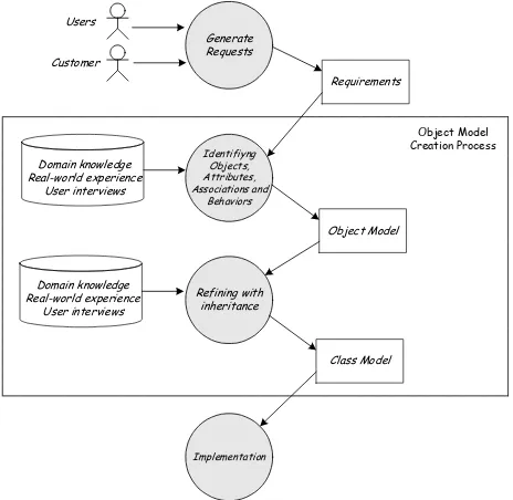
First of all, we summarized what is going on the object-oriented analysis and design process. As shown in Figure 1, object-oriented analysis and design begins with a problem statement (requirement) generated by end-users or customers. The requirement may be incomplete, and informal. Identification processes make it more precise and expose ambiguities and inconsistencies. The real-world system described by the requirement must be understood and identified, and its essential features abstracted into a model.
Users
Customer
Requirements
Identifiyng Objects, Attributes, Associations and
Behaviors
Object Model Domain knowledge
Real-world experience User interviews
Generate Requests
Refining with inheritance
Class Model Domain knowledge
Real-world experience User interviews
Implementation
Object Model Creation Process
Figure 1. An Overview of the Object Model Creation Process
Identifying objects, attributes, associations and behaviors of the object are important steps in constructing an object model. The next step is to organize classes by using inheritance to share common structure. Inheritance can be added in two ways [9]: by generalizing common aspects of existing classes into a superclass (bottom up or generalization approach), or by refining existing classes into specialized subclasses
(top down or specialization approach). The object
identification and refinement process are together called
object model creation process.
3.
Proposed Models for Requirement
Acquisition and Specification
3.1. Our Approach Toward Object-Based
Requirement Acquisition and Specification
Requirement acquisition is considered as one of the most important activities in software development [2]. The primary goal of the requirements document is to be
a reference for the software designers, facilitating improved software design through detection of incompleteness, inconsistency and ambiguity. Most of the faults found during testing and operation result from poor understanding or misinterpretation of requirements. In spite of progress in analysis techniques, Computer
Aided Software Engineering (CASE) tools support,
prototyping, early verification and validation, software development still suffers from poor requirements acquisition [10]. Until now, there are only a few effective methods and tools to guarantee a complete, consistent, and unambiguous requirement model [17]. Recent advances in software technology such as the development of the Unified Modeling Language (UML)
for object-oriented design have not reduced the need for better requirement acquisition and specification.
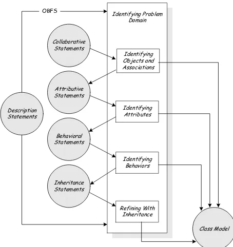
In the traditional approach to software analysis, system analyst interviews end-users to capture requirement. We propose an approach where end-users take an active role in the analysis by specifying requirements using Object-Based Formal Specification (OBFS) (Figure 2). We use OBFS to guide end-users in describing their problem. OBFS is composed of
Description Statements (DS), Collaborative Statements
(CS), Attributive Statements (AS), Behavioral Statements (BS), and Inheritance Statements (IS). This approach also takes advantage of end-users' domain knowledge.
A simple example of the software project for Air Traffic Control (ATC) system is given in this paper. It is provided for a comprehensive explanation about how to use the proposed method. This example is based on [7] [1].
3.2. Object-Based Formal Specification
Definition 3.1 (Object-Based Formal Specification
(OBFS)): Object-Based Formal Specification (OBFS) is
a semi-formal requirements template used to reveal ambiguity, incompleteness, and inconsistency in an object-oriented software system, and to guide end users take an active role while describing their problem statements. OBFS is composed of description statements (DS), collaborative statements (CS), attributive statements (AS), behavioral statements (BS), and inheritance statements (IS).
IS BS AS CS DS
OBFS= ⊕ ⊕ ⊕ ⊕ … (1)
Identifying Problem
Figure 2. Object Based Formal Specification
3.2.1. Description Statements (DS)
Description statements are used to guide for
writing an overview of the system that we want to build.
Description statements contain four kinds of elements:
Requirements ID, Requirements Name, Language, and
Description. The description statements should state
what is to be done and not how it is to be done. It should be a statement of needs, not a proposal for a solution.
Definition 3.2 (Description Statements (DS)): A description statement is a requirement statement used to write an overview of the system that we want to build, which consists of Requirement ID, Requirement Name, Language, and Description.
{
reqIDreqNameLanguageDescription}
DS= , , , … (2)
An example of DS for ATC system is shown in Example 3.1.
Example 3.1: DS of Air Traffic Control System
ReqID #001
ReqName Air Traffic Control System Language English
Description
Air Traffic Control (ATC) is chiefly concerned with managing aircraft in the neighborhood of an airport. An air traffic controller decides on the movement of aircraft. The purpose of this project is to develop an ATC for a metropolitan airport. The ATC provides an interactive display system runnable with a web browser and a display of a range of choices to be made by an air traffic controller during actual airport tower operation. The ATC has the capacity to play an important role in planning, monitoring, and control responsibilities of human specialists. The ATC provides the communication between human specialists and aircraft, to transmit information and control instructions. The ATC also provide the surveillance of air traffic, to determine the location, altitute, and speed of aircraft. The weather product availability is guaranteed, to assist in planning aircraft movement between locations.
3.2.2. Collaborative Statements (CS)
Collaborative statements (CS) are used to identify objects, and associations between objects. The first step in the object model creation process is to identify relevant objects and their association from the application domain. Objects include physical entities and all objects must make sense in the application domain. All objects are explicit in the collaborative statements. Objects correspond to nouns that are identified from collaborative statements. CS consists of a set of forms with contains Subject (S), Verb (V), and Object (O) as well as the English (E) natural language that is based on CS syntax rules. association (ASSt) in terms of object-oriented paradigm.
]
The CS syntax rules are listed as follows.
Predicates are extracted from synonym data dictionary (thesaurus) [14].
to Example 3.2.
Example 3.2: CS of Air Traffic Control System
TrafficManager manages Traffic. TrafficManager communicates with AirspaceTypeResource. TrafficManager drives CommunicationSystem. AirTrafficManager manages AirTraffic. AirTrafficManager communicates with AirspaceTypeResource. AirTrafficManager drives CommunicationSystem.
FlightManager manages Flight. FlightManager communicates with AirspaceType Resource. FlightManager drives CommunicationSystem. GroundTrafficManager manages GroundTraffic. GroundTrafficManager communicates with GroundTypeResource. GroundTrafficManager drives CommunicationSystem.
VehicleManager manages Vehicle. VehicleManager communicates with GroundTypeResource. VehicleManager drives CommunicationSystem. Aircraft refers to AirspaceTypeResource.
GroundVehicle refers to GroundTypeResource. VehicleSurveillanceSystem owns SurveillanceSystem. VehicleNavigationSystem owns NavigationSystem. VehicleCommunicationSystem owns CommunicationSystem.
Definition 3.3 (Collaborative Statements (CS)): A collaborative statement is an OBFS statement, which has a tuple {Scs,Vcs, Ocs}. An Object (OBJ) is derived from Scs and Ocs, and association between objects (ATT) is derived from Vcs.
3.2.3. Attributive Statements (AS)
Attributive statements (AS) are used to identify the attributes of objects. Attributes are properties of individual objects. Attributes usually correspond to nouns followed by possessive phrases, and sometimes are characterized by adjectives or adverbs. Attributive statement must contain properties of each object identified at the previous step. AS consists of a set of forms with contains Subject (S), Verb (V), and Object in the term of object-oriented paradigm. And Sas is identified and refined objects (OBJ) from tentative object (OBJt), as the final result of object identification’s process.
]
The AS syntax rules are listed as follows.
ntain of
Example 3.3: AS of Air Traffic Control System TrafficManager has AreaOfResponsibility.
Traffic has SelectionCriteria.
AirspaceTypeResource has Capacity, Configuration, Demand, Load, Location, Name, SaturationThreshold, SeparationMinima, UsageRestriction. AirTrafficManager has AreaOfResponsibility.
AirTraffic has SelectionCriteria. FlightManager has AreaOfResponsibility. Flight has Trajectory, Type.
GroundTrafficManager has AreaOfResponsibility. GroundTraffic has SelectionCriteria.
GroundTypeResource has Capacity, Configuration, Demand, Load, Location, Name, SaturationThreshold, SeparationMinima, UsageRestriction.
VehicleManager has AreaOfResponsibility. Vehicle has Vehicletype.
Aircraft has AircraftIdentification, Location.
GroundVehicle has GroundVehicleIdentification, Location. VehicleSurveillanceSystem has EquipmentType.
SurveillanceSystem has AreaOfCoverage, EquipmentType, Status. VehicleNavigationSystem has Equipmenttype, Status.
NavigationSystem has AreaOfCoverage, FrequencyChannels, IdentifierCode, Location, Status.
VehicleCommunicationSystem has ActiveFrequency, EquipmentType. CommunicationSystem has AreaOfCoverage, EquipmentType, Status.
Definition 3.4 (Attributive Statements (AS)): An attributive statement is an OBFS statement, which has a tuple {Sas,Vas, Oas}. Sas is an identified object (OBJ),
and Vas is a constant word, which shows that Oas is an attribute of Sas. The object’s attribute (ATT) is derived from Oas.
3.2.4. Behavioral Statements (BS)
Behavioral statements are used to identify object
behaviors. Behavior is how an object acts and reacts, in terms of state changes and message passing. A behavioral statement must contain behaviors of each object identified at the previous step. BS consists of a set of forms with contains Subject (S), Verb (V), and in the term of object-oriented paradigm. And Sbs is identified and refined objects (OBJ) from tentative object (OBJt), as the final result of object identification’s process.
]
The BS syntax rules are listed as follows.
ities) Example 3.4.
Example 3.4: BS of Air Traffic Control System AirspaceTypeResource has capabilities to UpdateDemand, UpdateLoad. AirTrafficManager has capabilities to DetectSaturation, PredictSaturation, ReportSaturation, DetermineAirspaceCapacity, ReserveAirspace, ResolveAirspaceSaturationProblem, SetAirspaceSaturationThreshold.
AirTraffic has capabilities to CreateAirTraffic.
FlightManager has capabilities to AssistFlightPlanning,
AssistWeatherAvoidance, DetectRestrictionViolation, PredictRestrictionViolation, ReportRestrictionViolation,
TransferControlResponsibility, AcceptContolResponsibility. Flight has capabilities to MaintainTrajectory.
GroundTrafficManager has capabilities to DetectSaturation, PredictSaturation, ReportSaturation, DetermineGroundCapacity, ResolveGroundSaturationProblem, SetGroundSaturationThreshold.
GroundTraffic has capabilities to Connect.
GroundTypeResource has capabilities to UpdateDemand, UpdateLoad.
VehicleManager has capabilities to AssistRoutePlanning, DetectRestrictionViolation, PredictRestrictionViolation, ReportRestrictionViolation, SeparateVehicles, TransferResponsibility, AccpetResponsibility.
Aircraft has capabilities to CreateFlight.
GroundVehicle has capabilites to CreateGroundVehicle.
VehicleSurveillanceSystem has capabilites to ReportAltitute, ReportIdentification.
SurveillanceSystem has capabilities to Connect, LocateFlight, IdentifyFlight, ReportFlight.
VehicleNavigationSystem has capabilities to AcceptNavigationalGuide, InterogateNavigational Aid, Navigate.
NavigationSystem has capabilities to Connect,Transmit Azimuth Information, TransmitRangeIdentifier.
VehicleCommunicationSystem has capabilities to AcceptMessage, SendMessage.
CommunicationSystem has capabilities to Connect, TransmitMessage.
Definition 3.5 (Behavioral Statements (BS)): An behavioral statement is an OBFS statement, which has a tuple {Sbs,Vbs, Obs}. Sbs is an identified object (OBJ),
and Vbsis a constant word, which shows that Obs is a behavior of Sbs. The object’s behavior (BEH) is derived from Obs.
3.2.5. Inheritance Sentences (IS)
Inheritance statements are used to organize classes by using inheritance, to share common object attributes and behaviors. Inheritance provides a natural classification for kinds of objects and allows for the commonality of objects to be explicitly taken advantage of in modeling and constructing object systems.
Inheritance statements provide sentences that describe
is-a-kind-of relationship.
Inheritance statements consists of a set of forms
with contains Subject (S), Verb (V), and Object (O) as well as the English (E) natural language that is based on
IS syntax rules.
Ois will be identified as a tentative superclass (SCLt) in the term of object-oriented paradigm. And Sis is identified and refined objects (OBJ) from tentative object (OBJt), as the final result of object identification’s process.
]
The IS syntax rules are listed as follows.
ization of Example 3.5.
Example 3.5: IS of Air Traffic Control System AirTraffic is a kind of Traffic.
GroundTraffic is a kind of Traffic. Aircraft is a kind of Vehicle. Aircraft is a kind of Flight. GroundVehicle is a kind of vehicle.
Definition 3.6 (Inheritance Statements (IS)): An
Inheritance statement is an OBFS statement, which has a tuple {Sis,Vis, Ois}. Sis is an identified object (OBJ), and Vis is a constant word, which shows that Ois is a superclass of Sis. The subclass (CLS) is derived from Sis, and the superclass (SCL) is derived from Ois.
4.
Proposed Models for Object Model
Creation Process
4.1. Object Identification Process
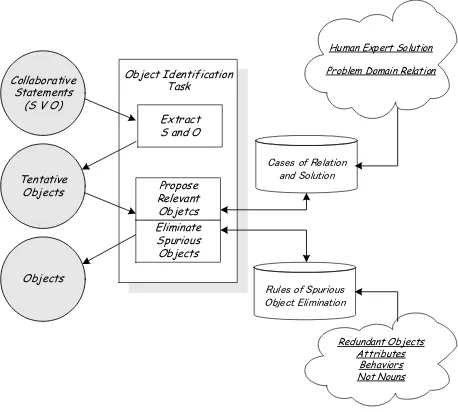
Figure 3 shows our strategy for the object identification process. We use collaborative statements (CS) from OBFS to guide end-users in describing their problem, especially for collaborative process in the system that end-users want to build. The first step in the object identification process is to extract S and O
written in the collaborative statements to be tentative objects (OBJt) (4). The tentative objects (OBJt) extracted from the collaborative statements of ATC system is as follows (Example 3.6).
Object Identification
Human Expert Solution Problem Domain Relation
Eliminate
Figure 3. Object Identification Process
The next step is to eliminate spurious objects and propose relevant objects using Rule-Based Reasoning (RBR) and Case-Based Reasoning (CBR) paradigms. In RBR, the system will discard unnecessary and incorrect objects according to the following criteria: redundant objects (OBJred), not noun objects (OBJnon), attributes (OBJatt), behaviors (OBJbeh), and associations (OBJass). The summary of object identification process is shown in Figure. 4.
]
[ OBJ OBJ OBJ OBJ OBJ
E
OBJ∈ ¬ red∧¬ att∧¬ beh∧¬ non⇒
∀
… (15) Two different kinds of case-base indexed in our CBR are called Human Expert Solution (HES) and
Problem Domain Relation (PDR). The final result of
the object identification process is a set of relevant objects (OBJ).
4.2. Association Identification Process
We use collaborative statements (CS) from OBFS to guide end-users in describing their problem, especially for collaborative process in the system that end-users want to build. The first step in the association identification process is to extract V written in the collaborative statements to be tentative associations (ASSt) (5). The tentative associations (ASSt) extracted from the collaborative statements of ATC system is shown as V of CS in the Example 3.2.
The next step is to eliminate spurious associations and propose relevant associations using Rule-Based Reasoning (RBR) and Case-Based Reasoning (CBR) paradigms. In RBR, the system will discard unnecessary and incorrect associations according to the following criteria: redundant associations (ASSred), not verb
associations (ASSnov), behaviors (ASSbeh), object (ASSobj), and attributes (ASSatt). The summary of association identification process is shown in Figure. 4.
]
[ ASS ASS ASS ASS ASS
E
ASS∈ ¬ red∧¬ att∧¬ beh∧¬ nov⇒ ∀
… (16) The final result of the association identification process is a set of relevant associations (ASS).
4.3. Attribute Identification Process
We use attributive statements (AS) from OBFS to guide end-users in describing their problem, especially for each object's property that is appeared in the system. The first step in the attribute identification process is to extract O written in the attributive statements to be tentative attribute (ATTt) (7). The tentative attribute (ATTt) extracted from the attributive statements of ATC
system is shown as O of AS in the Example 3.3.
The next step is to eliminate spurious attributes and propose relevant attributes using Rule-Based Reasoning (RBR) and Case-Based Reasoning (CBR) paradigms. In RBR, the system will discard unnecessary and incorrect attributes according to the following criteria: redundant attributes (ATTred), not noun attributes (ATTnon), objects (ATTobj), association (ATTass), and behaviors (ATTbeh). The summary of attribute identification process is shown in Figure. 4.
]
[ ATT ATT ATT ATT
E
ATT∈ ¬ red ∧¬ obj ∧ beh¬⇒
∀
… (17) The final result of the attribute identification process is a set of relevant attributes (ATT).
4.4. Behavior Identification Process
We use behavioral statements (BS) from OBFS to guide end-users in describing their problem, especially for each object's capability that is appeared in the system. The first step in the behavior identification
Object Model Creation
Process
Pre-Input (OBFS)
Extract
(S V O) Input Rules for Reasoning Output
Rules for Elimination
Object Identification
Collaborative
Statements S and O
Tentative Object
Redundant Object
Not
Noun Attribute Behavior Association Object Association
Identification
Collaborative Statements V
Tentative Association
Redundant
Association Not Verb Behavior Object Attribute Association Attribute
Identification
Attributive Statements O
Tentative Attribute
Redundant Attribute
Not
Noun Object Association Behavior Attribute
Behavior Behavioral Statements O
Tentative Behavior
Redundant
Behavior Not Verb Association Attribute Object Behavior Inheritance
Statements S and O
Object Hierarchy
Class Hierarchy
Rules for Similarity
Searching Rules for Superclass Naming
Object Refinement
with Inheritance
Identified Object from
Object Identification
Process
Attribute Behavior Similar Object’s Name
Given Name from User
Class Hierarchy
Figure 4. Summary of the Proposed Approach for Object Model Creation Process
process is to extract O written in the behavioral statements to be tentative behavior (BEHt) (10). The
tentative behaviorBEHt) extracted from the behavioral
statements of ATC system is shown as O of BS in the Example 3.4.
The next step is to eliminate spurious behaviors and propose relevant behaviors using Rule-Based Reasoning (RBR) and Case-Based Reasoning (CBR) paradigms. In RBR, the system will discard unnecessary and incorrect behaviors according to the following criteria: redundant behaviors (BEHred), not verb behaviors (BEHnov), associations (BEHass), attributes (BEHatt), and objects (BEHobj). The summary of behavior identification process is shown in Figure. 4.
]
[ BEH BEH BEH BEH BEH BEH
E
BEH∈ ¬ red∧¬ obj∧¬ ass∧¬ att∧¬ nov⇒
∀
… (18) The final result of the behavior identification process is a set of relevant behaviors (BEH).
4.5. Object Refinement with Inheritance
Firstly, object refinement with inheritance process refers to inheritance statements (IS) directly for getting information about the hierarchy of objects according to end-user. The superclass-subclass hierarchy extracted from the inheritance statements (IS) of ATC system is as follows (Example 3.7).
Example 3.7: Class Hierarchy of Air Traffic Control System Based on IS
Superclass: Traffic Subclass: AirTraffic, GroundTraffic Superclass: Flight Subclass: Vehicle
Superclass: Vehicle Subclass: Aircraft, GroundVehicle
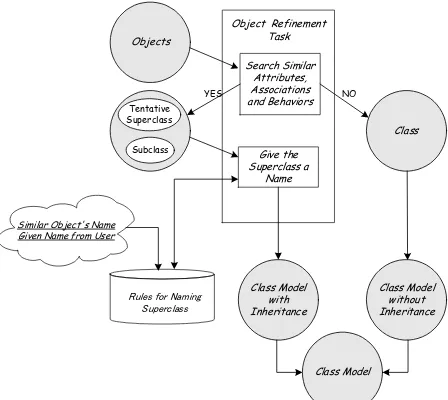
Furthermore, we use bottom-up (generalization) concepts as the basic approach to build a new model of object refinement process. As shown in Figure 5, object refinement with inheritance process begins by listing objects found in the previous object model creation process, and searching similar object names, attributes, and behaviors. If similar objects are found, the object will be belong to a subclass and a tentative superclass will be generated automatically.
The next process is to give the superclass a name. The superclass name can be given by the user, or automatically generated from similar object names. The result of this process is a class model with inheritance structure. If similar object cannot be found, the object will be a class model without inheritance structure. The final result of the object refinement process is a class model, which is the combination of the class model with inheritance and the class model without inheritance.
The summary of Object Refinement with Inheritance is shown in Figure 4.
Object Refinement Task Objects
Search Similar Attributes, Associations and Behaviors
Give the Superclass a
Name
Class Model with Inheritance
Similar Object's Name Given Name from User
Subclass Tentative Superclass
Class
NO YES
Class Model without Inheritance
Class Model
Figure 5. Object Refinement with Inheritance
5. System Architecture and Design
Software design often requires collaborative work among members of a software design project team. In many cases, the members are geographically distributed making the need for effective information and communication technologies acute. Agent-based approach is an alternative approach to achieve tasks on distributed computer systems [3]. This is intended to serve as a useful decision support system for designers, and should allow faster, better, and more economic, collaborative software analysis and design.
To date, the main areas in which agent-based applications have been reported are as follows: manufacturing, process control, telecommunication systems, air traffic control, traffic and transportation management, information filtering and gathering, electronic commerce, business process management, entertainment and medical care [13]. This research examines the issues associated with the use of agent-based approach within the software analysis and design.
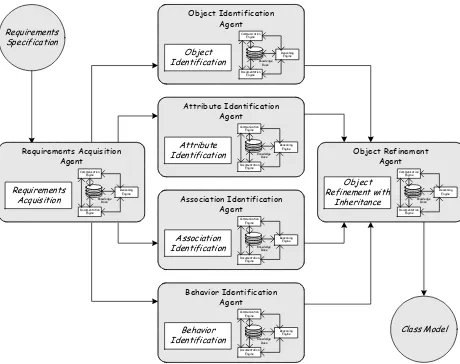
In our approach, object model creation process is viewed as a society of software agents that interact and negotiate with each other. We have devised six types of agents: requirement acquisition agent, object identification agent, attribute identification agent, association identification agent, behavior identification
agent, and object refinement agent (Figure 6). Each
agent is an intelligent in its own field and may interact with its human counterpart or behave autonomously. Each agent has a local knowledge base and a reasoning engine. All agents have a communication engine and a documentation engine. The communication and documentation engines facilitate communication and navigation of each agent on the network environment.
The responsibility of each agent is as follows. Firstly, the requirements acquisition agent manages the task concerning the requirements acquisition from
object-based formal specification (OBFS). The object
identification agent manages the task concerning the identification of objects. The attribute identification agent manages the task concerning the identification of object attributes. The association identification agent
manages the task concerning the identification of associations between the identified objects. The
behavior identification agent manages the task
concerning the identification of object behaviors. And finally, the object refinement agent manages the task concerning to refine objects and organize classes by using inheritance to share common structure.
Requirements
Figure 6. Intelligent Agent Architecture for Object Model Creation Process
6. Implementation
OOExpert is implemented using Java programming
language. Object model creation process is viewed as a society of OOExpert agents that interact and negotiate with each other. We have developed six types of
OOExpert agents.
Running all of the OOExpert agents are however, the first step toward working with OOExpert. When we start to run OOExpert agents, for example Requirement
Acquisition Agent, it will display a user interface
window as shown in Figure 7. The user interface window contains a standard toolbar, the viewer for OBFS tree and directories tree, and a control window.
Requirements Acquisition Agent displays OBFS menu
in the control window, including Description Statements, Collaborative Statements, Attributive Statements, Behavioral Statements and Inheritance
Statements. The user writes requirements in this place
based on OBFS standard. Especially for other
OOExpert agents, the reasoning processes of agents are displayed in this control window (Figure. 8).
Figure 7. Requirements Acquisition Agent
Figure 8. Object Identification Agent
Figure 9 shows the summary of how the OOExpert agents work. - Send OI request
- Socket and KQML - Send BI request
- Socket and KQML Based connection - Send OR request
- Socket and KQML Based connection - Send OR request
Figure 9. Summary of How the OOExpert
Agents Work
7. Related Work
In recent year, there are many research focusing on the methodology for identifying objects and its properties, i.e., behaviors, attributes, association [11] [21] [10], and the methodology for refining objects to share common structure.
Liang [21] proposed an approach to strengthen the process of object identification and selection, by considering the integration of object-oriented methods with a method of facilitating a rich appreciation of a problem situation and adding a new activity to the existing object-oriented analysis (OOA) process. The method used to bring about the appreciation of the problem situation that provides a way of modeling purposeful activities in a problem situation into an activity model. These activities represent the purposeful human actions in the situation that associate with actors, owners and customers. The actors, owners and customers are regarded as the basic elements of the situation as they perform, allow or request the activities. Liang [21] argues that they can be used as a base for identifying and selecting significant objects in OOA. Analysts are able to appreciate and understand such basic elements of a problem situation through the process of enquiry and then to specify them as significant objects into the object model.
Becker [11] proposed methodology called MOSYS
(Methodology for Object Identification for SYstem
Specification), which supports the design of distributed real-time systems. The methodology uses object-oriented models and UML (Unified Modeling Language) for system specification. As a first step of the methodology, external actors and objects that interact with the system are identified as the problem context. Elements of the object model that emerge from the analysis of the real problem are directly mapped into logical objects. Reuse constraints can also impose the definition of internal actors. Secondly and following the UML notation, use case diagrams are used to describe system functionality that is not directly associated with intuitive objects. Afterwards, a CASE tool is used to model use-case functionality, either by using activity diagrams or (and against UML) extended data flow diagrams (E-DFD). The components of E-DFD are weighted processes and weighted attributes (updated by the processes). Process and attribute weights are introduced to model process complexity and (virtual or real) timing constraints.
Drake [10] initiated a project called AURA
(Automated User Requirements Acquisition), which
takes advantage of end-users domain understanding. The central thesis of the AURA approach is that user-centered analysis will produce a higher quality specification than analyst-centered analysis. AURA uses a question-and-answer model to guide end-users in describing their problem. Additionally, AURA provides problem domain knowledge to suggest answers for the questions. When end-users perform analysis, the analyst
role becomes verification and validation of end-users’ analysis products. From the prototype and evaluation, Drake show that end-users can utilize a methodology-guided tool to input most of their requirements and input is consistent with the products of object-oriented analysis (OOA).
An interesting approach for eliciting software requirement is proposed by Komiya [18]. Komiya proposed a method for constructing the system to navigate the process of software engineering's eliciting software requirements by interviewing software customers over WWW. As a result of some experiments the topics adopted during an interview are classified into nine categories. We think that such results can be used to generate OBFS' description statements.
8. Conclusion
Although there are many project focusing on Computer Aided Software Engineering (CASE) tools for object-oriented analysis and design, there are only a few focusing on the formalization and implementation of the methodology for object model creation process. And also they are not developed well for the software design that requires collaborative working among members of a software design project team. In this paper, we proposed an approach where end-users take an active role in analysis by specifying requirements using Object Based Formal Specification (OBFS). We presented OBFS and its roles to be a methodological support for specifying requirements in object model creation process, including identification process and object refinement with inheritance process. The models and implementation for using OBFS are presented. A framework and system implementation for object model creation process is also presented.
9. References
[1] Celesta G. Ball and Rebecca L. Kim, An Object Oriented Analysis Of Air Traffic Control, WP-90W00542, the MITRE Corporation, McLean, Virginia, August 1991.
[2] F.P Brooks, No Silver Bullet, Essence and Accidents of Software Engineering, IEEE Computer, Vol. 20, No. 4, pp. 10-19, April 1987.
[3] Gerhard Weiss, Multiagent Systems: A Modern Approach to Distributed Artificial Intelligence, MIT Press, 1999.
[4] Grady Booch, James Rumbaugh, and Ivar Jacobson, The Unified Modeling Language User Guide,
Addison-Wesley, 1999.
[5] Grady Booch, Object-Oriented Analysis and Design with Application, Benjamin/Cummings, 1991.
[6] Ian M. Holland and Karl J. Lieberherr, Object-Oriented Design, ACM Computing Surveys, Vol. 28, No. 1, pp. 273-275, March 1996.
[7] James F. Peters and Witold Pedrycz, Software Engineering An Engineering Approach, John Wiley & Sons, Inc., 2000.
[8] James Rumbaugh, Ivar Jacobson, and Grady Booch, The
Unified Modeling Language Reference Manual,
Addison-Wesley, 1999.
[9] James Rumbaugh, Michael Blaha, William Premerlani, Frederick Eddy, and William Lorenson, Object-Oriented Modeling and Design, Prentice Hall, 1991.
[10] J.M. Drake, W.W. Xie, and W.T. Tsai, Approach and Case Study of Requirement Analysis Where end-users Take an Active Role, in Proceedings of the 15th International Conference on Software Engineering,
IEEE Computer Society Press, pp. 177-186, 1993. [11] L.B. Becker, C.E. Pereira, O.P. Dias, I.M. Teixeira and
J.P. Teixeira, MOSYS A Methodology for Automatic Object Identification from System Specification,
Proceedings of the Third IEEE International Symposium on Object-Oriented Real-Time Distributed Computing, Newport Beach, California, March 15-17, 2000. [12] Maritta Heisel and Jeanine Souquieres, Methodological
Support for Requirements Elicitation and Formal Specification, Proceedings of the 9th International Workshop on Software Specification and Design, Ise-Shima (Isobe), Japan, April 16-18, 1998.
[13] Nicholas R. Jennings, Katia Sycara, and Michael Wooldridge, A Roadmap of Agent Research and Development, in Autonomous Agents and Multi-Agent Systems, pp. 7-38, Kluwer Academic Publishers, Boston, 1998.
[14] Robert L. Chapman, Roget's International Thesaurus,
HarperCollins Publishers, 1992.
[15] Romi Satria Wahono and B.H. Far, Hybrid Reasoning Architecture for Solving Object Class Identification Problem in the OOExpert System, Proceedings of the 14th Annual Conference of Japanese Society for Artificial Intelligence, Tokyo, Japan, July 2000.
[16] Romi Satria Wahono and B.H. Far, OOExpert: Distributed Expert System for Automatic Object-Oriented Software Design, Proceedings of the 13th Annual Conference of Japanese Society for Artificial Intelligence, pp.456-457, Tokyo, Japan, June 1999.
[17] Ruqian Lu and Zhi Jin, Domain Modeling-Based Software Engineering, Kluwer Academic Publishers, 2000.
[18] Seiichi Komiya, Junzo Kato, Morio Nagata, Shuichiro Yamamoto, Motoshi Saeki, Atsushi Ohnishi, Hisayuki Horai, A Method for Implementing a System to Guide Interview-driven Software Requirements Elicitation,
The 4th Joint Conference on Knowledge-Based Software Engineering (JCKBSE2000), Brno, Czech Republic, 2000.
[19] Software Engineering Standards Committee of the IEEE Computer Society, IEEE Guide for Developing System Requirements Specifications, IEEE Std 1233-1998,
IEEE, New York, 1998.
[20] Software Engineering Standards Committee of the IEEE Computer Society, IEEE Recommended Practice for Software Requirements Specifications, IEEE Std 830-1998, IEEE, New York, 1998.
[21] Ying Liang, Daune West, and Frank A. Stowell, An Approach to Object Identification, Selection and Specification in Object-Oriented Analysis, in Information Systems Journal, Vol. 8, No. 2, 1998, pp. 163-180, Blackwell Science Ltd., 1998.