Architecture and Structure
–
Just a Simple Love Affair
Grohmann, M.1
Abstract: Behind challenging architecture there is always a challenging structure. To achieve the optimal result in a design process, architecture and structure have to be developed together. Starting from the first planning phases, the cooperation has to be a fruitful dialog involving complex geometry programs and structural calculation tools. The result of such planning processes is exemplified in this paper presenting just 2 projects Bollinger+Grohmann realized together with two different architects, i.e. The Rolex Learning Center for Ecole Polytechnique Federate de Lausanne (EPFL) in Lausanne with SANAA, Tokyo, and the new building for the European Central Bank (ECB) in Frankfurt with COOP Himme (1) blau Vienna. The aim is to prove that there is no contradiction between new architecture and structure, but just a simple love affair.
Keywords: Challenging architecture; challenging structure; simple love affair.
Introduction
Bollinger+Grohmann is an engineering firm founded in 1983 in Frankfurt, Germany. Meanwhile they are running offices in Berlin, Munich, Vienna, Paris, Oslo, and Melbourne. Their scope of work is struc-tural design, façade design, and building physics including thermal simulations. With over 150 engi-neers in total, they are working on projects almost all over the world.
This paper concentrates on two projects and gives details to design and building process.
- The Rolex Learning Center for Ecole Polytech-nique Federate de Lausanne (EPFL) in Lau-sanne with SANAA, Tokyo
- The new building for the European Central Bank (ECB) in Frankfurt with COOP Himme (l) blau Vienna.
The ROLEX LEARNING CENTER in
Lau-sanne
Project
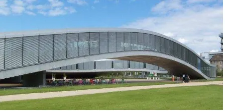
Together with the Tokyo based architectural firm SANAA, Bollinger+Grohmann did a couple of inte-resting buildings in Europe: The Design School at Zeche Zollverein in Essen [1,2], an office building for Novartis in Basel, The new building for Musée du Louvre in Lens [3,4], France and the new Rolex Learning Center for EPFL in Lausanne (Figure 1). Like the other building, the design for Rolex Learning Center was the result of an international architectural competition, in which the engineers already took part.
1 Bollinger+Grohmann Ingenieure, Westhafenplatz 1, 60327 Frankfurt, Germany Universität Kassel, Faculty of Architecture, 34125 Kassel, GERMANY. Email: [email protected]
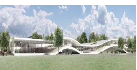
Figure 1. Rolex Learning Center, Lausanne, Rendering by SANAA
The program was to obtain a building with sufficient space for libraries, student work places, cultural activities etc. and to create a new representing entrance to the site of the EPFL [5]. The designing architects SANAA, Tokyo, responded to these demands by creating an architectural landscape which divides the different user zones naturally by hills and valleys instead of using walls and floors slabs.
Details of Building
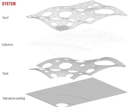
This landscape is built up by two shells with diffe-rent spans and intermediate flat slab areas. Due to the necessary accessibility of the inclined slab, the overall slenderness, ratio of height of shell to the span, was in the range of 1:18 [6]. In addition, the shell had to take the live load of the building and the loads of the roof.
The landscape is furthermore divided by patios which serve for the natural ventilation and lighting of the building. The entrances to the building are placed in the patios, too.
The basement is closed on the upper side by a concrete slab. This concrete slab serves on one side as floor of the main level (in between the shells and in the south-west and north-east building corners) on the other side, it fulfills an important structural function. It serves as horizontal bearing of the shells and takes up the horizontal bearing loads via posttensioning cables.
On top of this curved concrete slab are the columns that support the roof which is curved parallel with the concrete surface.
The most outstanding elements of the Rolex Learning Center are the curved slabs that due to their curvature attract extreme high normal forces (Figures 2-4).
Figure 2. Rolex Learning Center, Lausanne, Architectural Model of the Main Floor by SANAA
Figure 3. Structural Concept: Posttensioning Cables as Horizontal Bearings of the Shell
Figure 4. Structure of Rolex Learning Center
This shell action in these curved slabs was the biggest challenge for the structural engineers of the project. Therefore Bollinger+Grohmann Ingenieure developed in close cooperation with SAPS, Sasaki and Partner, Tokyo, and Walther Mory Maier, Basel, a concept that reconciled the high architectural demands, the user requirements and the structural aspects. The development was effected in close collaboration with the designing architects SANAA, here the form finding of the shells played an important role.
Development of Geometry
The geometry of the shells was developed based on the vision presented by the architects SANAA in the architectural competition. A compromise between the user requirements, the architectural design and the structural limits had to be found during the design process. The user aspects have been among others the request for sufficient usable flat areas, the respect of escape way lengths, the connections between different zones of the building, etc. Here the interests of handicapped people had to be considered in particular.
But also view axis had to be respected. This was important to cope with the exceptional panorama to the Swiss Alps given at the building site and so the view axis not only influenced the slopes of the shells but also the position of different patios [7].
The optimization process of the geometry started therefore with analyze of the geometries proposed by the architects. In this phase of the project the geometry was still subjected to major changes due to the user requirements, etc. The flat area between the two shells was, for example, extended to increase the flat surfaces that could be lot easier furnished for the users.
In the further design process the development of the geometry of the shells was an interactive procedure where the structural requirements were reconciled with the user requirements and the design aspects. Hereby the following aspects were tried to be imple-mented in the shell geometries (Figure 5 and 6): - Adaptation of the localization and geometry of
patio so that load bearing arches could be established between the patios
- Optimization of the geometry of the arches towards parabolic and symmetric sections - Reduction of imperfections
Figure 5. Analyze of Curvature of a Geometry Proposed by SANAA for the Small Shell with Recommendations in Regard to Structural Behavior (left side); Development of Patio Geometry (right side)
Figure 6. Arches and Slab Areas of the Shells
The big shell with spans up to 75 m and a maximum camber of 4.5 m has a disadvantageous span to camber relation with l/h = 16.7. Main load bearing arches could be established between the patios.
Conceptual Design
Simultaneously to the form finding process, different concepts for the structure where developed and examined. A solution proposing a steel structure was excluded at an early stage of the project as the architects desired a soffit in exposed concrete.
With the form finding process, the final solution with the so-called arches and slab areas emerged. First, only the grade of reinforcement differed between the arch section and the slab area sections. Later an alternative with variable section heights was favored.
In this alternative, the required height for the arches and the zones around the vertical load bearing elements and the patios of the big shell was 80 cm, whereas the height of the slab areas could be reduced to 60 cm. The smaller span of the small shell and its more advantageous span to camber relation
enabled a section height of 40 cm, respectively 50 cm for the western arch, for the small shell. The 60 cm zones were sufficient to place the technical equipment pipes, so that the total construction height could be limited also in this solution.
In the finally retained solution, the high amount of reinforcement is covered by reinforcement bars with a diameter of 50 mm, which guarantee sufficient space between the reinforcement bars for concreting. [8]
Detailed Design
The verification of the shells was done respecting to the Swiss Construction Standard, SIA. In several cases, other European standards or literature was consulted, as the construction standards do not respond to all questions evocated during the design of such an unusual construction.
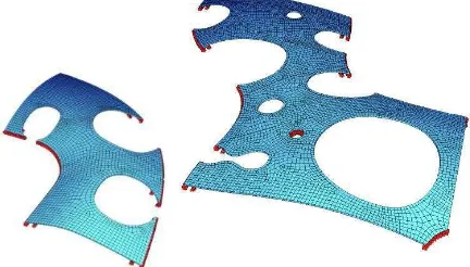
Three items influenced the design of the shells. Firstly, the verification of the sections under design loads and characteristic loads, secondly the deflections and finally the stability. All these items were analyzed considering the effects of: cracking, creep and shrinkage. Therefore, the shells were analyzed with non-linear finite element models with the program SOFiSTiK (Figures 7 and 8).
Figure 7. Slab with Upstanding Beams
The verification under design and characteristic loads was done respecting the limits given in the Swiss Building Standard.
Execution Planning of the Shell Structures
The required services of structural engineers during a design process are normally well defined in the Building Standards, but these definitions are achieving their limits for unusual projects as the Rolex Learning Center in Lausanne. Which infor-mation of a formwork drawing has to include in case of a free-formed surface, which information is necessary for the executing company to be in the position to build the formwork, to execute the form-work and reinforcement on site, etc. The beginning of the execution planning in this project was governed by this kind of questions. The close collaboration between the main contractor and the planning team allowed defining precisely the required information for the execution [9]. deflection already before construction. Therefore a second 3D-model aside the geometry model of the architects was established, which included the cambered geometry of the shell structures. During further design process it was so necessary to differentiate between the architectural model (non-deformed) and the structural model (cambered geometry) (Figure 9).
Figure 9. Formwork Drawing of a Patio Edge Including the Position of Formwork Table Joints
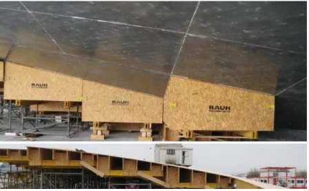
The formwork itself was prefabricated in factory in 2.50 m x 2.50 m formwork tables. Each of these tables consisted of two wooden base beams on which seven frames where fixed. The formwork facing consisting of 10 cm large wooden planks and a laminated chipboard panel was subsequently nailed on these frames. For the production of the formwork tables, the executing company worked further on the
data base of the 50 cm x 50 cm point grid and the structural 3D-model. The data was prepared so that all frames could be cut automatically computer-orientated. On site only the level of the steel scaffolding underneath the tables had to be adjusted exactly before placing the tables (Figure 10 and 11).
Figure 10. 3D Model of Formwork Table Frames; Prepa-ration of the Formwork Tables in Factory.
Figure 11. Formwork Tables on Site; After and Before Concreting
Reinforcement
The low curvature of the shells and the asymmetric geometry of the arches required not only a high performance concrete but also high percentage of reinforcement up to 470 kg/m³. The reinforcement was not only necessary for the transfer of traction in zones with high bending moments, but it reduced also the long term deflections due to creep and shrinkage.
Before starting the execution planning for the reinforcement it was decided to develop in close collaboration with the building company Losinger, concepts for the standard, critical reinforcement details. These details were the transition between arch and slab areas of the shell with changing reinforcement orientation, the transition between patio edge and slab area of the shells and the bearing of the shells including the layout of the construction joint.
Building
To handle the high amount of reinforcement in the arches and to assure sufficient gaps for concreting and vibrating, it was decided to use reinforcement bars with large diameters up to 50 mm. As these bars with these diameters can not be connected in the classical manner with overlapping, it was necessary to study other connecting alternatives. The high costs of screwed sockets turned the balance to welded joints. The welded joints were finally exe-cuted on site with the aid of a perforated socket which was placed around the end of the reinfor-cement bars and guaranteed the position of the bars during welding.
As the major parts of the shells are despite of the low curvature and the so induced high bending moments in all loading conditions exposed only to compression, it was decided to place a maximum of welding joints in these compression zones to reduce the number of eventual weak points in the structure. Therefore the zones which are eventually exposed to traction were identified and the layout of the 50 mm reinforcement bars was adapted accordingly (Figure 12).
Figure 12. Welded Joint of Diameter 50 mm Bars in Socket
For the transition between arches and slab areas with changing reinforcement orientation, mainly the positioning for the lower layers was to discuss. The upper layers were not, due to the different con-struction heights without conflict. The prototype for this detail served at the same time to test different formwork facings and the concrete composition in regard to ability to pump and viscosity. This was important to assure the concreting of the shells without counter formwork. As the first concrete compositions showed too much sensibility in regard to the water concentration, it was decided in the further development of the concrete composition to add plastic fibers. These fibers improved the behavior of the concrete during the vibration so that the shells could be executed without counter-formwork even in the zones with the maximum slope
A full design in 3D was necessary for the third and last prototype detail, the shell bearings. This was necessary to assure a right positioning and orienta-tion of the reinforcement bars corbelling outwards the construction joint between slab over the base-ment and the shells, up to 15% (Figure 13).
Figure 13. 3D-Model of the Shell Bearing Detail including the Posttensioning Cables and Anchors in the Slab over the Basement
As the formwork tables of the shells could not be placed before concreting the shell bearings, they could not serve as backing for the right orientation. Therefore two calibers were placed on the formwork of the slab over the basement, in which the reinforcement bars of the shell bearings were placed.
This was possible due to the close collaboration among all participants of the project. The Rolex Learning Center gave EPFL in Lausanne its representing entrance as it was demanded in the architectural competition (Figures 14 and 15).
The impressing images of the shells show that the original idea of an architectural landscape could be transferred in a building structure.
Figure 14. Big Shell after Removing of the Formwork
The New Buildings for the European
Central Bank (ECB) in Frankfurt
Background and Competition
Bollinger+Grohmann has a close cooperation history together with the architects of COOP Himmelb(l)au, Vienna for more than 20 years. Their first project has been the UFA Cinema Center in Dresden completed in 1996. Amongst others, they worked together for international well known projects like the BMW-Welt, Munich 2005 [10,11], the Dalian International Conference Center 2012, the Busan Cinema Center Busan, South-Korea 2012 [12,13], and the Musèe de Confluence, Lyon 2014.
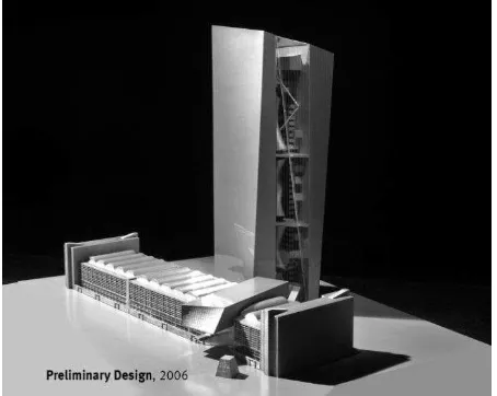
In 2002, the ECB launched an international urban and building design competition for their new headquarter. Along the conformance to several func-tional and technical requirements, the participating teams had the task to preserve the listed building called “Großmarkthalle” (Market hall) in its fundamental appearance and to integrate it in their design of the new ECB building [14,15] (Figures 16 and 17)
Finally in February 2004 the team of COOP Him-melb(l)au together with Bollinger+Grohmann was awarded first price.
Figure 16. Großmarkthalle (Market Hall) Built in 1928, 220 m long, 40 m wide, 40 m high
Figure 17. Preliminary Design by COOP Himmelb(l)au in 2006
Building Design
The commissioned design consists of three main structural elements: the glazed double tower, the market hall built in 1928, and the entrance structure inserted in the hall to connect all elements together (Figure 18). The North tower comprises 45 levels and has a height of 185 m, whereas the South tower comprises 43 levels and has a height of 165 m. An underground parking and additional buildings for the gates and the delivery area complete the complex of buildings. The gross floor area of the new ECB building is about 185000 m2.
The glazed atrium in-between the two office towers is designed to be a so-called “vertical city“, in which connecting platforms and bridges create semi-public spaces. The transfer levels divide the atrium into three vertical sections. These connecting platforms are accessible via the bridges, the ramps and the stairs of the levels above and below.
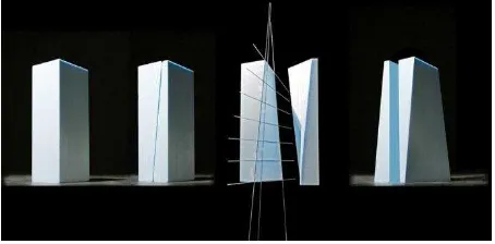
A rectangular solid was used as basis for the spatial layout. The architects then divided this volume diagonally along its height with a rotating cut. The cutting planes of both parts were then turned to the outside, meaning that the previously external faces are now internal. In addition, one part of the build-ing was turned upside-down such that the smaller floor area (about 700 m2) is now at the bottom and
the slightly larger area (up to 1200 m2) at the top
(Figure 19). As a result of this rotating cut, standard surfaces are formed that each displays a straight vertical and horizontal generatrix. The double-curvature of these surfaces on a single façade element is so small that the resulting offset can be accommodated in the joint of the façade elements [16,17].
Figure 19. The Geometrical Operation for Developing the Hyperbolic Paraboloid (HP) Surfaces
Structure of the High-rise
The internal façades of the two towers remain flush and vertical towards the atrium. The vertical circulation of the building is located inside the atrium, where there are four transfer platforms accessible with the five express lifts of the atrium. From there, the employees continue to their office floors via five separate lifts. This configuration minimizes the number of lifts while ensuring acceptable travel times. Simultaneously, the transfer platforms generate important communication areas.
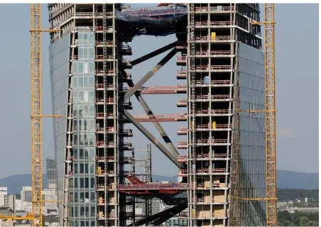
The relocation of the circulation areas into the atrium allowed to reduce the required depth of the concrete cores to 6 m containing the stairs and risers. This was beneficial for an efficient layout of the available floor area. It is this functional optimisation of the core area that constitutes a challenge for the stability of the two towers. Due to the reduced depth of the core of only 6 m, it was not feasible to provide enough stability to the 180 m high towers. Therefore it was necessary to develop an additional stability system to support the cores. The design idea of the atrium connecting the two towers could therefore also be used with a structural meaning. The concrete cores of both towers at a distance of about 26 m were connected to one structural system by the means of connecting structural elements. Thus the stability system of the combined towers is much more rigid than for the separate towers. The connecting structural elements consist of steel struts and beams in the platforms, acting together with the concrete cores as a spatial truss structure. The cores form the top and bottom chords while the struts and beams in the platforms act as posts and diagonals. The effective depth of the stability system could thus be increased from 6 m to 26 m.
In the longitudinal direction, the two towers are braced by their concrete core. Due to the eccentric position of the towers as well as the overhang in the façade, the self-weight and wind load induces torsion which is absorbed by the spatial stability system (Figure 20).
Figure 20. Principal Elements of the Structural System: Cores, Slabs, Bracings with Struts and Platforms
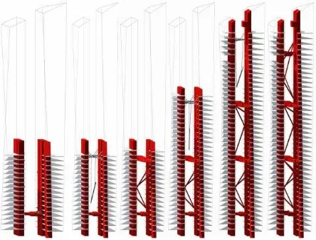
Development of the Strut Geometry
The position and number of the struts is essential to the performance of the stability system. During the design phase, various studies have been carried out to determine the optimal geometry of the struts for the high-rise. Along the structural and architectural requirements, it was necessary to consider also functional requirements. The struts could only be situated where they would not interact with the lifts, bridges and other elements inside the atrium.
A parametric generating process was used to assist with the optimisation studies in order to rate the numerous options. At first, a random strut geometry was analysed with a simplified stability model. Further options and strut configurations were then developed parametrically by using the characteris-tics of the improved system, similar to the evolution theory. Adopted rating criteria were the maximum strut resistance as well as the natural frequency and stiffness of the building.
towers by the generating process. Thus, an irregular spatial truss structure is created which is optimised regarding the previously defined criteria for strut resistance and stiffness. In order to better demon-strate the principles of the free layout of the struts, an alternative version of the process was developed to show the struts as continuous strips. This is more similar to the traditional image of continuous diagonals in a truss structure (Figures 21-23).
These two principles were developed further in order to fulfill the requirements for fire protection, which did not allow the struts to cut through the main platforms. As a consequence, the struts were considered to be one unit for each third of the towers. Again, a free layout and a continuous strip were analysed for these thirds. The strut geometry with the continuous elements proved to be the best option regarding structural and functional aspects. Due to the higher loads in the bottom third, elements with six instead of four diagonals were used there.
Figure 21. Parametric Generating Process of the Strut Layout
Due to the overall vertical truss system, all horizontal loads had to be transferred by the struts. This resulted in high node forces for the connection details where the forces of the struts were trans-ferred into the concrete cores.
Figure 22. Connection Detail Between Struts and Cores in the Workshop
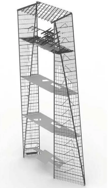
Figure 23. View through the Future Atrium. In-between the Two Towers There are Struts and Platforms
Analysis and Calculation of the Structural Behavior Under Construction
The combined system of the concrete cores with the struts and platforms provides the definitive stiffness for the two towers. One individual tower - without the link to the other tower - would not be able to withstand the horizontal loads due to the inclined geometry of the building and the resulting forces, as well as the wind loads.
The north-east corner experiences the largest rotation due to the biggest distance from the shear center.
Figure 24. Erection Sequence
In order to represent the strength and deformation behavior in a realistic way, the stiffness calculations considered the various construction phases. Thus the calculations were not performed with a model representing only the final state, but analysed in detail for each determined construction progress. In the analysis model, certain elements were therefore combined into a construction phase. During this analysis, the deformation, strain and resulting forces from the floor levels below were accounted for with pre-determined stress and strain states, similar to the cantilever method in bridge construction. In addition to a realistic representation of the resulting forces, this method allowed to assess the deformation behavior of the towers continuously from start of construction until the completion of the core and shell structure. This was important considering the fact that the towers were given a pre-determined horizontal deformation in order to obtain vertical façade surfaces towards the atrium. During the installation of the formwork, a corrective factor was applied to the four external corners of each slab with the opposite value of pre-determined deformation. As the calculated deformation values were based on assumptions, the actual deformation was measured continuously, documented and compared with the calculated values. A corrective factor was determined and applied in the consequent floor levels in case of a difference between actual and target value.
Structural Slab and Column System
Another challenge consisted in developing an appropriate structural slab and column system. Due to the floor geometry with inclined façades, each one of the 80 slabs has a different geometry. A regular column grid throughout all the levels was therefore
not applicable. For example, vertical internal columns in the upper levels of the North tower could not be transferred down geometrically to the foundation due to the overhang in the North façade. Several studies concluded that the following system is the best solution: the façade columns at a distance of 5.80 m follow the geometry of the external skin and are thus inclined in one direction. In the slender sides of the façade, some of the adjacent columns intersect and are then combined to one single continuous column. The internal columns are situated inside the functional areas (e.g. technical rooms and washrooms) to provide a more flexible use of the office space. Some of the internal columns are vertical and others are inclined in two directions.
With the aim of keeping the same cross-section of the columns for all levels, variations of composite cross-sections and high-performance concrete were used as necessary. The resulting spans of the chosen column grid facilitated a flat slab system. In areas with larger spans, the slab was post-tensioned with unbonded tendons to limit the deflections. These zones had to be designed carefully to avoid that the post-tensioning of specific zones is transferred to the surrounding areas, thus reducing the post-tensioning in the required part.
Foundations
In Frankfurt, the most economical foundation system for high-rise buildings has proven in recent years to be a combination of piles together with a slab (so-called Combined Pile-Raft Foundation). The skin friction and base resistance of the piles as well as the bearing capacity of the raft transfer the loads into the ground.
The combined foundation system of the new building for the ECB had to provide a total capacity of 2700 MN. This required 97 large bored piles of Ø 120 cm and a maximum length of 37 m, and a raft with varying thickness of 1.50 m to 3.50 m according to the applied loads. The piles are situated below the columns and the core walls. Steps in the raft and an integrated ductwork required a detailed coordination of the reinforcement.
The column loads are supported proportionately via the pile capacity as well as the bending of the raft and the soil pressure.
Figure 25. Structural Behavior of Combined Pile-Raft Foundation
Facade of the Atrium
Together with the atrium roof, the atrium façade forms the building skin for the atrium. A distinctive feature of both façades is the inclined kink as a geometric result of the tower design development, such that each of the two façade surfaces is planar.
The sub-structure for the façade elements consists of a free-standing mullion-transom-structure composed of welded steel hollow sections. The posts of the 180 m high façade are supported on the ground and transfer the total vertical load of the façade via concrete columns in the basement levels into the raft. Deformation due to temperature at the top of the façade is enabled by a vertically free connection to the atrium roof. The corner posts of the façade are connected to the towers with a connection allowing vertical movement. In every third level there are horizontal beams connected to the towers that brace the façade against wind loads.
Figure 26. The Kink in the Atrium-facade
Due to the large span of these beams, additional supports in the form of horizontal struts are required. In addition to these loads, the façade structure experiences restraining forces from the different rotation in the towers. The geometry of the towers produces a kink in the section of these bracing beams (Figures 26 and 27). This kink helps to absorb the restraining forces by using the step between the two beam axes as if it was a spring.
Figure 27. The 180 m High Atrium Façade is a Self-supporting Structure with regards to the Vertical Loads. The Horizontal Loads like Wind are Transferred to the Towers
Completion
Figure 28. Exterior View of the Twin-towers with HP-façade
Figure 29. The ECB Ensemble after Completion with Grossmarkthalle in front
Concluding Remark
Although the title may appear a bit provocative the author hopes that he could make clear what he wants to state: Being a civil engineer we all must not only be experts in our field of specialization. Without a lot of passion for our profession we won´t get the appreciation in our societies that we deserve.
References
1. Schmal Cachola, P., Zollverein School of Mana-gement and Design, In: Schmal Cachola, P.,
Editor, Workflow: Struktur – Architektur, Birk-häuser Verlag für Achitektur, Basel, 2004. 2. Techen, H., Bollinger, K., and Grohmann, M.:
Die integrierte Planung der Zollverein School of Management and Design, DETAIL, 12/2005, S. 1466.
3. Bollinger, K., Grohmann M., Pfanner, D., and Nowak, S., Louvre Lens - Einfachheit und Kom-plexität, In: Bundesingenieurkammer, Inge-nieurbaukunst 2014, Ernst & Sohn GmbH & Co. KG, Berlin, 2014.
4. Pfanner, D. and Grohmann, M., Leichtes Trag-werk, Filigrane Fassade für den Louvre-Lens, In: Christian Schittich, Editor, DETAIL Einfach und Komplex, Serie 5/2013, München.
5. Weilandt, A., Bollinger, K., and Grohmann, M., Formfinding of the Shells of the Rolex Learning Center in Lausanne, IASS 2009, Evolution and Trends in Design, Analysis and Construction of Shell and Spatial Structures, Valencia, 2009. 6. Geipel, K., Äußerst Flache Schalen, Bauwelt,
42/2008, S. 34.
7. Jäger, F., Freier Blick bis zum Mont Blanc, In: Schittich, C. and Schmal Cachola P., Editors,
Bollinger + Grohmann, DETAIL Engineering 3, München 2013
8. Bollinger, K., Grohmann, M., Weilandt, A., Wag-ner, M., Walther, R., Santini, R., and von Ah, S.: Das Rolex Learning Center der EPFL in Lau-sanne, Beton- und Stahlbetonbau, Ernst & Sohn Verlag, Berlin, Heft 4, 2010, S. 248.
9. Weilandt, A., Bollinger, K., and Grohmann, M., From Conceptual Design to Execution, Rolex Learning Center in Lausanne, IASS 2009, Evo-lution and Trends in Design, Analysis and Cons-truction of Shell and Spatial Structures, Valen-cia, 2009.
10.Peseke, M., Grohmann, M., and Bollinger, K., The Großmarkthalle in Frankfurt/Main - an Early Reinforced Concrete Shell Structure, Per-ceived Technologies in the Modern Movement 1918 – 1975, do_co_mo.mo., 2014.
11.Köppl, J., Ludwig, H., Schidzig, R., and Wagner, S., BMW-Welt München – die Stahlkonstruktion in der realen Umsetzung, Stahlbau, Ernst & Sohn Verlag, Berlin, 07/2005.
12.Santifaller E. and Pfanner, D., Imageträchtige Bühne für Urbanes Leben – Busan Cinema Cen-ter, In: Bundesingenieurkammer, Editor, Inge-nieurbaukunst made in Germany 2012/2013,
Junius-Verlag, Hamburg 2012.
13.Pfanner, D., Bollinger, K., and Jeon, B.S., Die Dächer das Busan Cinema Centers, Stahlbau, Ernst & Sohn Verlag, Berlin, 12/2012.
15. Peseke, H., Bollinger, K., and Grohmann, M., The Großmarkthalle in Frankfurt/Main, IASS 2009, Evolution and Trends in Design, Analysis and Construction of Shell and Spatial Struc-tures, Valencia, 2009.
16. Santifaller, E., Symbolische Metamorphosen, In: Schittich, C., and Schmal Cachola, P., Editors,
Bollinger + Grohmann, DETAIL Engineering 3, München 2013.