PHOTOGRAMMETRIC TECHNIQUES FOR ANALYSIS AND VISUALIZATION OF
CHANGES IN 2D AND 3D DATA: PLASTIC SURGERY APPLICATION
V. A. Knyaz a,b, S.Yu. Zheltov a,b, A. Chibunichev c, a
State Research Institute for Aviation System (GosNIIAS), Moscow, Russia – (knyaz, zhl)@gosniias.ru
b
Moscow Institute of Physics and Technology (MIPT), Moscow, Russia c
Moscow State University of Geodesy and Cartography (MIIGAiK), Moscow, Russia - [email protected]
Commission II, WG II/10
KEY WORDS: Photogrammetry, 3Dreconstruction, shape changes, visualization, human body, texturing, data fusion
ABSTRACT:
Accurate measurements of 3D scenes and change detection of spatial distributed data are of great importance in different areas of research and application. For more accurate data analysis it is useful to take into account the all available data from various sensors and sources. The common case is that the different kinds of data available in their own coordinate systems and it is needed to transform all data in common coordinate system. This can be provided by finding correspondence between features in data of different types and different sources. Photogrammetry provides structurally connected 2D and 3D data which gives valuable information about correspondence of 2D and 3D features. The approaches to 2D and 3D data fusion and analysis are proposed which are based on complex processing of 2D and 3D data for changes detection and visualization. The techniques for data fusion are developed. The results of applying the developed techniques are presented for plastic surgery application.
1. INTRODUCTION
For more than twenty years various digitalizing systems of a human body are available for using in wide spectrum of applications. A set of systems and methods are presented for human body measurements which can be classified into three main classes: laser-scanning based systems, system using a projection of light patterns and a combined techniques of modeling and image processing.The detailed overview of 3D body scanning technologies with applications to the fashion and apparel industry is presented in (D’Apuzzio, 2007).
The description of different methods of human body 3D scanning are presented in (Remondino, 2003), (Schrotter, 2005), (Straub and Kerlin, 2015), and others. New sensors and techniques are applied for human body 3D data acquisition an analysis such as infrared (Tran et al, 2014) and terahertz (Tian et al, 2017) imaging.
The main tendency for automation of data processing leads to involving techniques for anatomical landmarks detecting, tracking and recognizing. In (Sitnik and Witkowski, 2008) a set of shape parameters describing local features of a surface is
Precise measurements of human body surface geometric parameters and analysis of shape changes due to various reasons are very important for wide variety of applications such as medicine, identification, garment design and manufacturing etc. But often it is impossible to perform required measurements with given precision as in case of post-burn surgery when a
healthy tissue area. A photogrammetric technique for accurate 3D surface models generating and 2D and 3D data analysis is proposed. The approach is to reconstruct accurate 3D model of body surface and to carry out measurements using this 3D model. The hardware of the developed system includes a set of CCD cameras, frame grabber, structural light projector. Original software allows to scan surface of human body, to generate textured 3D model and to perform given measurement procedures. Produced 3D models have real scale and photorealistic texture providing reliable data for processing
The reconstruction of extensive post burn deformations remains a challenging problem for plastic surgery. The main difficulty is a deficiency of healthy tissues and therefore complexity of plastic surgery planning. The basis for successful results of an operation is the precise measurement of damaged and adjacent healthy tissues and the accurate forecast of tissue expansion.
Existing 1D and 2D methods for measuring the required areas on the patient body could not give accurate results because of significant curvature of the measured surface. So a photogrammetric technique for precise measurements is proposed. The interested part of body surface is reconstructed using calibrated two cameras stereo system and structured light projector. Then area calculations of the given regions (damaged and adjacent healthy tissues) are performed using textured 3D model. In most cases the whole region of interest could not be reconstructed from one position of the photogrammetric system. So a set of 2.5D models is needed for obtaining the representative 3D model of the area of an interest. The original software is developed for semi-automated 2.5D fragments merging into the united 3D model and performing semi-automated area measurements.
using monochrome cameras as system components. The advantages of the proposed 3D system are high precision and fast processing in conjunction with relatively low cost, safety and convenience for a patient.
2. HARDWARE OUTLINE
2.1 Requirements
In addition to general requirements of high accuracy and high productivity of measurements some special requirements are imposed for human body 3D reconstruction system. They are:
Short processing time because of difficulty for a person to keep immobility
Convenience and safety for captured person Producing 3D model for given part of body
Colour texturing of the 3D model to capture visual features of scanning area
To meet these requirements the system configuration shown in Figure 1 is chosen.
Figure 1. System configuration
It includes:
Two high-resolution Basler a601f cameras for non-contact photogrammetric measurements
Colour high resolution camera for colour texturing of 3D model (optional)
PC controlled structured light projector for automated correspondence problem solution
PC as central processing unit
The developed system is based on photogrammetric principle of spatial measurements, which allows determining 3D coordinates for any point of the object if its image correspondence for two oriented photographs is established. The system provides automated images orientation (calibration) and supports a set of methods of automated correspondence problem solution based on various structured light patterns such as scanning stripe, coded light, phase shift.
2.2 Calibration
Calibration provides camera interior and exterior orientation parameters estimation. It is performed using plane test field with coded targets as reference points.
Image interior orientation (principal point xp, yp, scales in x and y directions mx, my, the radial symmetric distortion coefficients K1,K2,K3 and decentering distortion coefficients P1,P2) and image exterior orientation (Xi, Yi, Zi - location and i,i,i and angle position) are estimated in automated mode after acquiring a set of 12 test field images for each camera (Knyaz, 2010)..
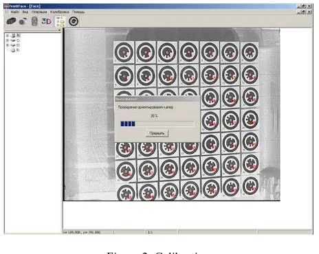
Figure 2. Calibration
Original calibration software provides automated test field image processing and orientation parameters estimation basing on observations. The process of calibration is shown in the Figure. 2.
The residuals of co-linearity conditions for the reference points are considered as a calibration criterion. The results of calibration provides the accuracy of = 0.04 mm.
3. HUMAN BODY 3D MODEL GENERATION
3.1 2.5 Scanning
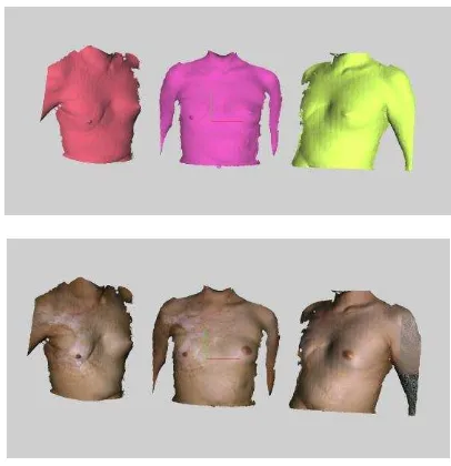
Figure 3. A set of 2.5D fragments scanned for 3D model generation
The number of fragments (scans) depends on complexity of the scanned surface. The number of scans should be great enough to cover all area of interest and have overlapping region for merging fragments. In case of complex shape of scanning region (like the head of a patient during preparation for plastic surgery, Figure 3) the number of scans increases to capture all significant points of the surface.
The 3 partial fragments of a body scanned by developed system are shown in Figure 3. As a result of 2.5D scanning a set of textured partial fragments is generated, every fragment being in own local coordinate system (Figure 3).
3.2 Single mesh generation
To obtain united 3D model from a set of 2.5D fragments two techniques are realized. For 2.5D fragment having sufficient common parts the semi-automated technique of matching overlapped part is used. An operator roughly adjusts two fragments in initial approximation position and then alignment is refined automatically using iterative closest points algorithm (Besl, and McKay, 1992).
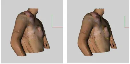
The result of fragments merging is shown in Figure 4.
Figure 4. Fragments merging
In case when overlapped regions are insufficient for registration or merging fragments do not have significant geometric features for iterative closest points matching merging based on reference points correspondence is performed. For applying this technique an operator marks three or more corresponding reference points on adjacent fragments and then transition matrix is determined for fragments merging.
The 3D model obtained by fragments merging could not be directly used for specific application processing, firstly, because of having overlapped surfaces which hinder to perform necessary measurement and, secondly, because of poor texture quality which prevent to find areas of interest on the surface. So the next stages of 3D model processing are united 3D model generation and integrated texture mapping.
Figure 5. Single mesh generation
United 3D model is produced by integrating all scans into single mesh using interpolating mesh algorithm (Curless and Levoy, 1996). The result of single mesh generation is shown in Figure 5.
3.3 Texturing
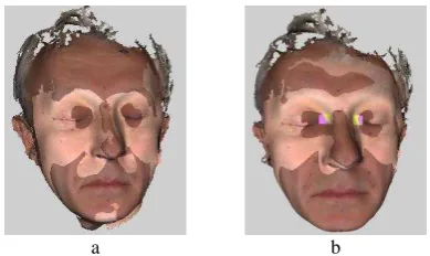
Direct texture mapping from oriented colour images gives poor results because of images for texture are acquired from different point and in different light condition. The common case of texture representation after textured fragments merging without additional processing is not suitable for using texture for required area determination and measurement (Figure 6 b).
a b
So for texturing the special image processing is applied with the aim of obtaining photorealistic quality of 3D model. For every colour image used for texturing the region of corresponding 2.5D scan is determined in the image. Then for every triangle of single mesh 3D model corresponding coordinates of its vertexes are found in every colour image containing this triangle.
Figure 7. Conjoint texture
For every colour image in which given triangle presents image intensity for pixels inside this triangle is averaged with weight depending on triangle location in the initial fragment. The result of refined texture generating is presented in Figure 7.
4. RECONTRUCTIVE PLASTIC SURGERY FORECAST
The reconstruction of extensive post burn deformations remains a challenging problem for plastic surgery. The main difficulty is a deficiency of healthy tissues and therefore complexity of plastic surgery planning. The basis for successful results of an operation is the precise measurement of damaged and adjacent healthy tissues and the accurate forecast of tissue expansion.
Existing 1D and 2D methods (Figure 7 a,b) for measuring the required areas on the patient body could not give accurate results because of significant curvature of the measured surface.
a b c
Figure 8. 1D (a) and 2D (b) manual measurements and expanders (c)
To provide additional healthy tissue to reconstruct post burn deformations special expanders (Figure 7c) are used. They are placed under healthy tissue and allow to stretch it for use in subsequent reconstruction.
4.1 Measurements
United textured 3D model allows carrying out measurements required surgery planning. The software supports calculating of linear distances on the surface, calculating area inside the given contour marked by an operator on the surface. An operator draws a border of an area to be measured using colour texture information for determining damaged and healthy tissues. Then the software calculates the area inside the border.
Figure 9. Area of spatial region calculation
Figure 9 demonstrates the results of area selection and calculation for 3D surface region inside the contour needed for operation forecast.
For predicting the results of operation the system works in two modes. In preliminary forecasting mode an operator chooses the type of expander and its position on 3D model and the software calculates the results of tissue expanding depending on injected liquid volume. Then area of reconstructed tissue is calculated. In preoperative mode an operator marks the contour of the area of expanded tissue over real expander on 3D model reconstructed directly before an operation, and the software calculates tissue expanding from data about real expanded area.
Figure 10: Forecast function for plastic surgery
5. SHAPE CHANGES ANALYSIS AND VISUALIZATION
Quantitative analysis of human body shape allows plastic surgeon to make adequate decisions on reasons and treatment of different surgery cases. Photogrammetry provides the powerful basis for body shape measurements, changes analysis and visualization. Basing on the photogrammetric 3D scanning system described above a set of techniques intended on acquiring 3D models in different conditions and shape changes detecting and measuring is developed (Murynin, Knyaz, and Matveev, 2014). Original software being a part of the system allows to match 3D models, to transform them in common coordinate system, to perform necessary joint measurements and to visualize changes in various forms (Knyaz and Gaboutchian, 2016).
Many tasks in plastic surgery require to obtain body 3D models in different conditions and to compare shape changes. So a set of algorithms for supporting these requirements is developed.
5.1 3D models acquiring
For acquiring body 3D models original photogrammetric system was used. It produces accurate dense 3D models mapped by accurate photorealistic texture. The system is designed as mobile device allowing to perform 3D scanning in different
patient’s position needed for studying.
Figure 11 presents two 3D models obtained in different conditions (while patient is seating and while patient is lying down).
a b
Figure 11. Two 3D models obtained in different conditions: (a) patient is seating, (b) patient is lying down.
The first stage is visual analysis of the shape changes is performed by visualization software module. It implements functions of showing a 3D model in wireframe or surface mode and in textured mode. Visual analysis allows making preliminary decision on first steps for shape modification. Also it is possible to choose needed pose for a 3D model which shows the shape of some face contours which are important for surgeon.
Such type of representing allows surgeon to clear recognize the main regions of shape changes in different patient position. The most modified region for the case presented in Figure 12 is a middle area of a face.
5.2 3D models matching
Along with qualitative visual analysis of textured 3D models it is important for plastic surgery to perform some measurements showing the degree of shape changes.
a b
Figure 12. Two 3D models obtained in different conditions: (a) patient is seating, (b) patient is lying down.
Several types of transformation are supported: by a set of reference points, by a whole 3D model surface, by a set of 3D model surface patches. Figure 12 presents the results of two 3D models matching basing on various criteria for transformation in common coordinate system. L2 metrics is used for point-based transformation. For surface-point-based transformation a
metrics of “point-surface distance” is applied. The left image (a) corresponds to the result of matching two models basing on all surface analyzing, and the right image (b) – the result of matching two models basing on partial surface fragments analyzing.
5.3 Quantitative shape changes analysis
For more detailed quantitative analysis of shape changes a set of predefined calculations and visual presentation forms are developed, such as shape differences map, surface section visualization and linear parameters calculation for required section, area of surface regions calculation and comparison and the determination of volumetric characteristics of changes.
It is important for plastic surgery to perform some measurements showing the degree of shape changes. So different 3D models transformed in common coordinate system are used to calculate required geometric parameters.
Figure 13 presents the results of quantitative analysis of face surface deformations presented as a surface to surface distance.
Visualization of shape changes in a form of a surface-to-surface distance map allows to show the tendency and degree of surface displacements. For the case shown in Figure 13 the main displacements occur in neck regions.
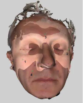
Figure 14. Anthropological points used for surface shift analysis for different patient positions.
The estimate of displacements for several anthropological reference points (Figure 14) shows the regions of main changes (in temple area and under eye area) and the regions with minimal shifts (upper lip area).
Table 15 presents the calculation results of reference point displacements for points shown in Figure 14.
Point # Distance, mm
Photogrammetry is a powerful mean for acquiring structurally connected 2D and 3D data which is useful for shape changes analysis. The developed techniques for such data processing, analysing and visualization allows to establish correspondences between 3D models obtained in different conditions, to calculate a set geometrical parameters for quantitative analysis, to present data in various forms for visual study and for forecast of changes being result of planning actions.
The developed algorithms and software was used for quantitative and visual shape changes analysis in plastic surgery field. The quality of the proposed techniques is demonstrated on reconstructive surgery of post burn deformations cases and plastic surgery
The results of developed technique application for plastic surgery analysis and panning tasks proved the necessary accuracy and functionality along with required quality of visualization.
ACKNOWLEDGEMENTS
The reported study was funded by Russian Foundation for Basic Research (RFBR) according to the research project № 15 -08-Videometrics VIII, 260 (February 28, 2005); doi:10.1117/12.586902
Straub, J., Kerlin S., 2015; A very low-cost 3D scanning system for whole-body imaging. Proc. SPIE 9487, Smart Biomedical 8952, Biomedical Applications of Light Scattering VIII, 89521A (March 4, 2014); doi:10.1117/12.2038474.
Sitnik R, Witkowski M; Locating and tracing of anatomical landmarks based on full-field four-dimensional measurement of human body surface. J. Biomed. Opt. 0001;13(4):044039-044039-11.
Remondino F., 2003: 3D Reconstruction of Static Human Body with a Digital Camera. Proc. SPIE 5013, Videometrics VII, 38 (January 20, 2003); doi:10.1117/12.473090.
Tian L, Shen Y, Jin W, Zhao G, Cai Y, 2017: Processing and fusion of passively acquired, millimeter and terahertz images of the human body. Opt. Eng. 0001;56(4):043102. doi:10.1117/1.OE.56.4.043102.
Besl, P., McKay, N., 1992: A method for registration of 3-D shapes, IEEE Transactions on Pattern Analysis and Machine Intelligence, vol. 14, no.2, pp. 239-256, 1992
Curless, B., Levoy M., 1996: A Volumetric Method for Building Complex Models from Range Iimages, SIGGRAPH 96 Conference proceedings, pp. 303-312, 1996.
Knyaz, V. A. and Gaboutchian, A. V., 2016:
PHOTOGRAMMETRY-BASED AUTOMATED
MEASUREMENTS FOR TOOTH SHAPE AND OCCLUSION ANALYSIS, Int. Arch. Photogramm. Remote Sens. Spatial Inf. Sci., XLI-B5, 849-855, doi:10.5194/isprs-archives-XLI-B5-849-2016, 2016.
Murynin, A., Knyaz, V., and Matveev, I., 2014: Human Vision Pathology Diagnostics by Photogrammetrics Means. Int. Arch. Photogramm. Remote Sens. Spatial Inf. Sci., XL-5, 437-443, doi:10.5194/isprsarchives-XL-5-437-2014, 2014.