THE USE OF 3D DEPTH CYCLORAMAS IN MUNICIPAL PROCESSES
B.J. Beers, J. Broere, A. Swart, P. Joosten
CycloMedia Technology B.V., Waardenburg, The Netherlands
bbeers@cyclomedia.com
Commission IV/8
KEY WORDS: Mobile, Mapping, Multisensor, Registration, Point Cloud, Three-dimensional, Precision
ABSTRACT:
The use of digital panoramic imagery in processes at municipal and cadastral authorities has become common over the last decade. Applications are found among situational awareness, inventory of public areas, real estate valuation, assessment of permits and inspecting security risks. More and more the imagery is being used for measuring and map making.
To enhance the quality and effectiveness of the applications and to improve the user friendliness of measuring and map making, a new dimension has been added to the panoramic images: the 3rd dimension. The principle and process behind these so-called Depth Cycloramas is briefly explained and their possibilities in municipal practice are demonstrated. Differences with the employment of LiDAR point clouds concerning precision and possibilities are detailed. Attention is paid to the excellent possibilities offered by Depth Cycloramas for projecting 2D and 3D maps and designs, for stereo viewing and for deriving detailed 3D information of object geometry and object texture.
1. INTRODUCTION
The use of digital street level panoramic imagery in various geo-related processes at municipal and cadastral authorities has become common over the last decade. Advantages of street level imagery over aerial imagery are the natural human perspective and the more detailed view. Applications are found in asset inventories and conditions assessments of public areas, in risk assessment and control, in preparation, training and evaluation for disaster management, in real estate valuation and in assessment of permits.
1.1 Measuring and map making
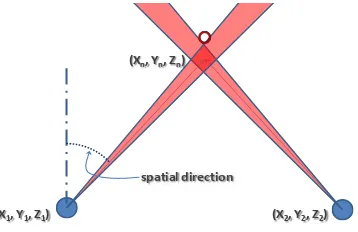
More and more panoramic imagery is being used for measuring and map making in 2D as well as in 3D, sometimes along with aerial stereo imagery. Stereo viewing from two standard panoramic images is not practical because of the lack of binocular disparity in at least half the field of view, as well as the large differences in scale of projection of similar objects, resulting in large perceived differences between objects in foreground and background. Therefore, to obtain geometric data for measuring and map making, multi-image measurements following the land surveying intersection principle (Figure 1) have to be employed.
(X1, Y1, Z1) (X2, Y2, Z2)
spatial direction (Xn, Yn, Zn)
Figure 1. Schematic representation of point measurement using forward intersection principle
Measuring from panoramic images demands some special requirements, not found in common panoramic imagery. First, the imagery must show adequate detail, requiring suitable image quality and recording interval, thus allowing correct interpretation of features to be measured. Second, panoramic imagery must be geometrically (=photogrammetric) correct to a level where accurate measurement results as required can be obtained. Finally, the geographical position and orientation of every panoramic image should be known with a specified absolute accuracy. Besides these requirements, suitable measuring tools incorporating a proper implementation of a calculating method for land surveying are required. Preferably the calculating method has integrated quality control procedures, allowing immediate user feedback of e.g. measurement tolerances and errors.
For instance, to obtain an absolute point accuracy in the order of 10 cm (‘GIS grade’), the location accuracy of panoramic imagery that is used in the measuring process should also be in the order of 10 cm. The accuracy of the image orientations should be 0.1° or smaller, whilst the image resolution should be such that the pixel size corresponds to a spatial angle of 0.1° or smaller. Cycloramas fulfill these requirements.
The employment of multi-image measurements in large scale operation leaves way for efficiency improvement because of the repetitive steps the operator has to fulfill. To allow single-image measurements, by adding a third dimension to pixels in the panoramic image, so-called Depth Cycloramas are introduced. Also Depth Cycloramas enhance the user-friendliness of measuring and map making by improving the quality and effectiveness of the workflow, therefore making the process accessible to a wider audience.
1.2 Depth Cycloramas vs. LiDAR point clouds
correspondences between images in areas with insufficient texture. However, another source for the addition of depth to panoramic imagery comes from mobile LiDAR systems. Although the point clouds from these systems are usually less dense than those based on stereo from images, they offer reasonably reliable 3D data and do not suffer from loss of information in areas without texture. Because of the advantages of LiDAR data, in further research these point clouds are used for adding depth to panoramic imagery.
As advertized by vendors of LiDAR based mobile mapping systems (MMS), the current practice in the employment of LiDAR point clouds in combination with (panoramic) imagery is (Method 1) to colorize the point clouds using color information from the images or (Method 2) to use the image as a foreground “curtain” in which the user points at an object and retrieves the 3D coordinates from a section in the point cloud using a local surface reconstruction. This reconstruction is required as otherwise most of the times the direction the user was pointing at will ‘miss’ all points in the point cloud. In this paper, a new approach of combining LiDAR point clouds and panoramic imagery into Depth Cycloramas is proposed.
Figure 2. Adding a depth and quality layer to image data in order to obtain a Depth Cyclorama
Figure 2 shows the principle of storing a depth layer in combination with (panoramic) image data. A traditional image consists of three ‘layers’, containing the actual image pixels in terms of R, G and B values. A depth layer “D” is added, for each pixel containing a depth (=distance from the recording location to the object ‘under’ a pixel). Additionally, a quality layer “Q” is added, describing the quality of the depth for that pixel, in terms of precision and reliability.
2. OVERVIEW OF THE PRODUCTION OF DEPTH LAYERS
In order to obtain depth information for the panoramic images, it is necessary to register them to LiDAR point clouds. When a mobile mapping system records both panoramas and LiDAR data, registration can be performed by using known calibration parameters (the relative setup between sensors). It is also possible that the panoramas and the LiDAR point cloud were acquired at different times. In this case, registration can be performed using a combination of SIFT (Lowe, 2004) interest point matching, the Iterative Closest Point algorithm (Besl and McKay, 1992) and Bundle Adjustment.
During registration, care has to be taken to reduce influences of parallaxes that occur between datasets. These parallaxes are an effect of non-coincidence of the image and LiDAR sensors in space and time. They occur in simultaneous and non-simultaneous recording approaches and can be expected to be larger with the latter approach. Parallaxes could be stored in such a way that in a later phase, users of the final data will be warned not to try measuring in these areas.
Before depth information can be projected onto the images as depth layers, there are still several problems to solve. When projecting the LiDAR point cloud onto a depth layer, not every pixel will have a corresponding depth value and occlusion has not been handled.
To give every pixel a depth value and to handle occlusion correctly, after registration we interpolate between points in the LiDAR data by generating a triangle mesh (Carlberg et al., 2008) as shown in Figure 3. The depth layer is then generated by sampling depth values from the mesh at each pixel.
Figure 3. A triangle mesh generated from a LiDAR point cloud
There could still be mismatches between image pixels and their corresponding depth values. These mismatches are most obvious near edges, and arise due to the quality of the registration itself, geometric distortions in the point cloud, mesh generation errors, and the limited LiDAR sampling rate. The last depth-to-image mismatch effects can be solved by locally deforming the depth map. This means that the depth map of an image is morphed towards the image itself using, for example, edge information. An example of a panorama with corresponding depth layer is illustrated in Figure 4.
Figure 4. An example of a panoramic image and a grayscale representation of its corresponding depth layer
3. ADVANTAGES OF USING DEPTH CYCLORAMAS
images and over the use of LiDAR point clouds (whether used in a colorized version or used in combination with imagery as a foreground “curtain”) where in the process as described above discrepancies have been revealed with geometrically correct panoramic imagery.
3.1 Navigation
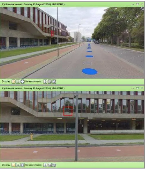
In comparison with traditional panoramic images, having a depth layer allows easier and more intuitive navigation through the environment. Knowing depth essentially allows navigation in a 3D environment, making the implementation of a user experience using a 3D mouse possible. Façades can be identified from the depth data and represented by a rectangle (Figure 5). Also street surfaces can be identified and are represented by a circle cursor.
Figure 5. Navigation through Depth Cycloramas using depth data to identify a façade, represented by the rectangle cursor:
a double click in the top window results in a jump to the picture shown in the bottom window.
3.2 Single image measurement
In those cases where traditional panoramic imagery is being used for the georeferencing of visible objects, like when performing street inventories, determining the location of an object requires the use of a minimum of two panoramic images and determining the location by means of intersection. When a depth layer is available, such measurements can be performed in a single image with a single click, as now for every pixel X, Y and Z coordinates can be obtained directly. An important feature now is the instant availability of the quality of the calculated coordinates.
Figure 6. Example of point measurement in a single image
Figure 7. Example of line measurement in a single image
Figure 8. Example of area measurement in a single image
especially the case when measuring narrow objects such as poles, or when attempting to measure edges of objects such as buildings. Offsets between the images and the point cloud might exist, causing the user to unknowingly measure the wrong object.
3.3 Projection of geographic data
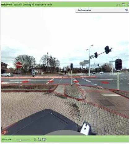
As a result of the metric correctness of Cycloramas it is possible to overlay projections of 2D and 3D geographic data. Figure 9 shows the addition of point data, in this case traffic signs that were collected with a semi-automatic procedure from the same Cycloramas.
Figure 9. Point data overlaid on aerial image and on Cyclorama
As map data at present is mostly available as 2D data, the only way to project this data in a plain Cyclorama is to assume the Z-value to be at the street level where the panoramic image was taken (equals Z of image minus camera height). Of course this will only lead to adequate results if the terrain is relatively flat (see Figure 10).
Figure 10. 2D map data overlaid on plain Cyclorama
A Depth Cyclorama will allow draping the 2D data over the Z-values, thus rendering a more precise view.
In case 3D data is available, projection will work best and will offer very comprehensible views (see Figure 11) on both plain and Depth Cycloramas.
Figure 11. 3D data overlaid on plain Cyclorama
Moreover, the depth layer allows projection of 2D and 3D maps and designs (not only vector data, but raster/voxel data as well) with removal of occluded features (see Figure 12). One should be aware of the fact that, in general, maps are simplified compared to reality, while the depth layer is not. This might occasionally lead to removing lines that a user would actually want to see and sometimes showing lines that shouldn’t be seen. In that respect it is advised not to remove occluded lines but to shade them.
3.4 Stereo display
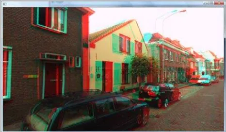
Having depth information available allows the panoramic images to be displayed in stereo over the full 360°. From a Depth Cyclorama an image for the left and the right eye need to be generated. Display of the left and right image to the human eyes can be done using numerous techniques (Wikipedia, 2011).
Figure 13. Stereo viewing using anaglyph technique
When using a single image with its associated depth layer, the resulting stereo image slightly suffers from imperfections due to occlusion. This is because parts of the scene visible to one of the two eyes are not necessarily visible in the panorama. A more advanced panoramic stereo viewer could use the depth and color information for the occluded parts from neighboring images to overcome this problem. Alternatively it is possible to store multiple depth and color layers per panorama like in layered depth panoramas (Zheng et al. 2007), but in practice it makes storage and use more complicated.
Having the possibility of stereo display available can enhance image interpretation. This in turn leads to better and easier object classification. Additionally, improved image interpretation leads to better measurement quality, as it becomes easier to identify objects to be measured. Measurements become more reliable, as identification errors become less likely.
3.5 Façade textures
Having the combination of imagery and a depth layer allows for more reliable cut outs of façade textures. In order to avoid the problems of occlusion, it is possible to use data from several neighboring images and depth maps. While this is possible, one should be aware of the fact that the process becomes more complicated, as one needs to merge/blend both the textures and the 3D data from the different panoramas. However because of the good match between imagery and depth layer, the resulting cut-outs will be of higher quality than those based on imagery alone.
3.6 Storage
Storing depth layers is very similar to storing RGB values, which means there is no need for a special storage format for point clouds. This also implies that no specific software like for retrieval of point clouds is needed. Obviously more storage is needed, the amount depending on the selected compression methodology. Compression of depth layers can be lossless or lossy, where in case of lossy compression, there is a tradeoff between compression ratio and quality.
In order to use depth layers in combination with the associated panoramic imagery, only extensions to standard viewing tools are needed. It is not necessary to produce completely new software. Therefore users will only need little training to familiarize themselves with the additional options the depth layers provide.
3.7 Backward compatibility
Besides all mentioned advantages, a Depth Cyclorama is ‘backward compatible’ with a plain panorama. The actual visible information, the RGB values, is not changed. Depth information is only added, no image information is modified or removed. Consequently when applying a sensible file format, existing viewing software for plain panoramic imagery can be used without modification. In that case however the advantages of Depth Cycloramas cannot be exploited.
4. CONCLUSIONS
The authors have proposed a novel way of combining panoramic imagery with point cloud data. Compared to two “traditional” methods of using point cloud data, the new approach leads to a more user-friendly use, thus enhancing the possibilities for using the data as well as the quality of interpretation and measurement results in practices as found in municipal and cadastral organizations. Compared to traditional panoramic images, the approach leads to enhanced usability of the images, while maintaining the easy visually oriented approach traditional panoramic imagery offers the user.
ACKNOWLEDGMENTS
Part of this research has been supported by the GATE project, funded by the Netherlands Organization for Scientific Research (NWO) and the Netherlands ICT Research and Innovation Authority (ICT Regie).
REFERENCES
Besl, P.J. and McKay, N.D., 1992. A method for registration of 3-D shapes. IEEE Transactions on pattern analysis and
machine intelligence, 14(2), pp. 239-256.
Carlberg, M., Andrews, J., Gao, P. and Zakhor, A., 2008. Fast surface reconstruction and segmentation with ground-based and airborne LiDAR range data. International Symposium on 3D
Data Processing, Visualization and Transmission, pp. 97-104.
Lowe, D.G., 2004. Distinctive image features from scale-invariant keypoints. International Journal of Computer Vision, 60(2), pp. 91-110.
Wikipedia, 2011. Stereoscopy, http://en.wikipedia.org/wiki/
Stereoscopy (accessed: May 19, 2011)
Zheng, K.C. and Kang, S.B. and Cohen, M.F. and Szeliski, R., 2007. Layered depth panoramas. IEEE Conference on