Approval Date: 2012-03-09
Publication Date: 2012-04-04
External identifier of this OGC® document: http://www.opengis.net/spec/citygml/2.0
Reference number of this OGC® project document: OGC 12-019
Version: 2.0.0
Category: OpenGIS® Encoding Standard
Editors: Gerhard Gröger, Thomas H. Kolbe, Claus Nagel, Karl-Heinz Häfele
OGC City Geography Markup Language (CityGML)
En-coding Standard
Copyright © 2012 Open Geospatial Consortium.
To obtain additional rights of use, visit http://www.opengeospatial.org/legal/.
This document is an OGC Member approved international standard. This document is
available on a royalty free, non-discriminatory basis. Recipients of this document are
invited to submit, with their comments, notification of any relevant patent rights of
which they are aware and to provide supporting documentation.
Document type: OpenGIS® Encoding Standard
Document subtype: Encoding
Document stage: Approved for public release
ii Copyright © 2012 Open Geospatial Consortium.
License Agreement
Permission is hereby granted by the Open Geospatial Consortium, ("Licensor"), free of charge and subject to the terms set forth below, to any person obtaining a copy of this Intellectual Property and any associated documentation, to deal in the Intellectual Property without restriction (except as set forth below), including without limitation the rights to implement, use, copy, modify, merge, publish, distribute, and/or sublicense copies of the Intellectual Property, and to permit persons to whom the Intellectual Property is furnished to do so, provided that all copyright notices on the intellectual property are retained intact and that each person to whom the Intellectual Property is furnished agrees to the terms of this Agreement.
If you modify the Intellectual Property, all copies of the modified Intellectual Property must include, in addition to the above copyright notice, a notice that the Intellectual Property includes modifications that have not been approved or adopted by LICENSOR.
THIS LICENSE IS A COPYRIGHT LICENSE ONLY, AND DOES NOT CONVEY ANY RIGHTS UNDER ANY PATENTS THAT MAY BE IN FORCE ANYWHERE IN THE WORLD.
THE INTELLECTUAL PROPERTY IS PROVIDED "AS IS", WITHOUT WARRANTY OF ANY KIND, EXPRESS OR IMPLIED, INCLUDING BUT NOT LIMITED TO THE WARRANTIES OF MERCHANTABILITY, FITNESS FOR A PARTICULAR PURPOSE, AND NONINFRINGEMENT OF THIRD PARTY RIGHTS. THE COPYRIGHT HOLDER OR HOLDERS INCLUDED IN THIS NOTICE DO NOT WARRANT THAT THE FUNCTIONS CONTAINED IN THE INTELLECTUAL PROPERTY WILL MEET YOUR
REQUIREMENTS OR THAT THE OPERATION OF THE INTELLECTUAL PROPERTY WILL BE UNINTERRUPTED OR ERROR
FREE. ANY USE OF THE INTELLECTUAL PROPERTY SHALL BE MADE ENTIRELY AT THE USER’S OWN RISK. IN NO EVENT SHALL THE COPYRIGHT HOLDER OR ANY CONTRIBUTOR OF INTELLECTUAL PROPERTY RIGHTS TO THE INTELLECTUAL PROPERTY BE LIABLE FOR ANY CLAIM, OR ANY DIRECT, SPECIAL, INDIRECT OR CONSEQUENTIAL DAMAGES, OR ANY DAMAGES WHATSOEVER RESULTING FROM ANY ALLEGED INFRINGEMENT OR ANY LOSS OF USE, DATA OR PROFITS, WHETHER IN AN ACTION OF CONTRACT, NEGLIGENCE OR UNDER ANY OTHER LEGAL THEORY, ARISING OUT OF OR IN CONNECTION WITH THE IMPLEMENTATION, USE, COMMERCIALIZATION OR PERFORMANCE OF THIS INTELLECTUAL PROPERTY.
This license is effective until terminated. You may terminate it at any time by destroying the Intellectual Property together with all copies in any form. The license will also terminate if you fail to comply with any term or condition of this Agreement. Except as provided in the following sentence, no such termination of this license shall require the termination of any third party end-user sublicense to the Intellectual Property which is in force as of the date of notice of such termination. In addition, should the Intellectual Property, or the operation of the
Intellectual Property, infringe, or in LICENSOR’s sole opinion be likely to infringe, any patent, copyright, trademark or other right of a third party, you agree that LICENSOR, in its sole discretion, may terminate this license without any compensation or liability to you, your licensees or any other party. You agree upon termination of any kind to destroy or cause to be destroyed the Intellectual Property together with all copies in any form, whether held by you or by any third party.
Except as contained in this notice, the name of LICENSOR or of any other holder of a copyright in all or part of the Intellectual Property shall not be used in advertising or otherwise to promote the sale, use or other dealings in this Intellectual Property without prior written authorization of LICENSOR or such copyright holder. LICENSOR is and shall at all times be the sole entity that may authorize you or any third party to use certification marks, trademarks or other special designations to indicate compliance with any LICENSOR standards or specifications.
This Agreement is governed by the laws of the Commonwealth of Massachusetts. The application to this Agreement of the United Nations Convention on Contracts for the International Sale of Goods is hereby expressly excluded. In the event any provision of this Agreement shall be deemed unenforceable, void or invalid, such provision shall be modified so as to make it valid and enforceable, and as so modified the entire Agreement shall remain in full force and effect. No decision, action or inaction by LICENSOR shall be construed to be a waiver of any rights or remedies available to it.
Copyright © 2012 Open Geospatial Consortium. iii
Contents
i.
Abstract ... ix
ii.
Preface and Acknowledgements ... ix
iii.
Submitting organizations ... ix
iv.
Submission contact points ... x
v.
Participants in development ... x
vi.
Changes to the OGC
®Abstract Specification ... xi
vii.
Acknowledgments ... xi
Foreword ... xii
0
Introduction ... xiv
0.1
Motivation ... xiv
0.2
Historical background ... xiv
0.3
Additions in CityGML 2.0 ... xv
1
Scope ... 1
2
Conformance ... 2
3
Normative references ... 2
4
Conventions ... 3
4.1
Abbreviated terms ... 3
4.2
UML Notation ... 4
4.3
XML namespaces and namespace prefixes ... 6
4.4
XML-Schema ... 7
5
Overview of CityGML ... 9
6
General characteristics of CityGML ... 11
6.1
Modularisation ... 11
6.2
Multi-scale modelling (5 levels of detail, LOD) ... 11
6.3
Coherent semantical-geometrical modelling ... 12
6.4
Closure surfaces ... 12
6.5
Terrain Intersection Curve (TIC) ... 13
6.6
Code lists for enumerative attributes ... 14
6.7
External references ... 14
6.8
City object groups ... 14
6.9
Appearances ... 15
6.10
Prototypic objects / scene graph concepts ... 15
6.11
Generic city objects and attributes ... 15
iv Copyright © 2012 Open Geospatial Consortium.
7
Modularisation ... 17
7.1
CityGML core and extension modules ... 18
7.2
CityGML profiles ... 23
8
Spatial model ... 25
8.1
Geometric-topological model ... 25
8.2
Spatial reference system ... 28
8.3
Implicit geometries, prototypic objects, scene graph concepts ... 28
8.3.1 Code lists ... 30
8.3.2 Example CityGML datasets ... 30
8.3.3 Conformance requirements ... 31
9
Appearance model ... 33
9.1
Relation between appearances, features and geometry ... 34
9.2
Appearance and SurfaceData ... 36
9.3
Material ... 37
9.4
Texture and texture mapping ... 38
9.5
Related concepts ... 44
9.6
Code lists ... 44
9.7
Conformance requirements ... 44
9.8
Material model of previous CityGML versions [deprecated] ... 46
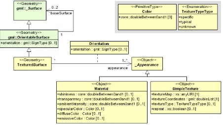
9.8.1 Textured surfaces ... 47
9.8.2 Conformance requirements ... 48
10
Thematic model ... 49
10.1
CityGML Core ... 50
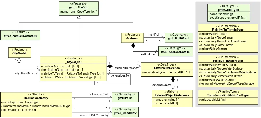
10.1.1 Base elements ... 52
10.1.2 Generalisation relation, RelativeToTerrainType and RelativeToWaterType ... 53
10.1.3 External references ... 54
10.1.4 Address information ... 54
10.1.5 Code lists ... 56
10.1.6 Conformance requirements ... 56
10.2
Digital Terrain Model (DTM) ... 57
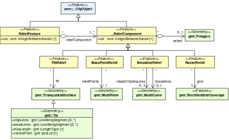
10.2.1 Relief feature and relief component ... 58
10.2.2 TIN relief ... 59
10.2.3 Raster relief ... 59
10.2.4 Mass point relief ... 60
10.2.5 Breakline relief ... 60
10.2.6 Conformance requirements ... 61
10.3
Building model ... 62
10.3.1 Building and building part... 64
10.3.2 Outer building installations ... 68
Copyright © 2012 Open Geospatial Consortium. v
10.3.4 Openings ... 73
10.3.5 Building interior ... 74
10.3.6 Modelling building storeys using CityObjectGroups ... 76
10.3.7 Examples ... 76
10.3.8 Code lists ... 78
10.3.9 Conformance requirements ... 78
10.4
Tunnel model ... 82
10.4.1 Tunnel and tunnel part ... 84
10.4.2 Outer tunnel installations ... 87
10.4.3 Boundary surfaces ... 87
10.4.4 Openings ... 91
10.4.5 Tunnel interior ... 92
10.4.6 Examples ... 94
10.4.7 Code lists ... 94
10.4.8 Conformance requirements ... 95
10.5
Bridge model ... 99
10.5.1 Bridge and bridge part ... 102
10.5.2 Bridge construction elements and bridge installations ... 104
10.5.3 Boundary surfaces ... 106
10.5.4 Openings ... 109
10.5.5 Bridge interior ... 111
10.5.6 Examples ... 112
10.5.7 Code lists ... 114
10.5.8 Conformance requirements ... 114
10.6
Water bodies ... 119
10.6.1 Water body ... 121
10.6.2 Boundary surfaces ... 121
10.6.3 Code lists ... 123
10.6.4 Conformance requirements ... 123
10.7
Transportation objects ... 124
10.7.1 Transportation complex... 127
10.7.2 Subclasses of transportation complexes ... 128
10.7.3 Subdivisions of transportation complexes ... 130
10.7.4 Code lists ... 130
10.7.5 Conformance requirements ... 130
10.8
Vegetation objects ... 132
10.8.1 Vegetation object ... 134
10.8.2 Solitary vegetation objects ... 134
10.8.3 Plant cover objects ... 135
10.8.4 Code lists ... 135
10.8.5 Example CityGML dataset ... 135
10.8.6 Conformance requirements ... 136
vi Copyright © 2012 Open Geospatial Consortium.
10.9.1 City furniture object ... 138
10.9.2 Code lists ... 139
10.9.3 Example CityGML dataset ... 139
10.9.4 Conformance requirements ... 140
10.10
Land use ... 141
10.10.1 Land use object ... 142
10.10.2 Code lists ... 142
10.10.3 Conformance requirements ... 143
10.11
City object groups ... 144
10.11.1 City object group ... 144
10.11.2 Code lists ... 145
10.11.3 Conformance requirements ... 145
10.12
Generic city objects and attributes ... 146
10.12.1 Generic city object ... 147
10.12.2 Generic attributes ... 148
10.12.3 Code lists ... 149
10.12.4 Conformance requirements ... 149
10.13
Application Domain Extensions (ADE) ... 150
10.13.1 Technical principle of ADEs ... 150
10.13.2 Example ADE ... 151
10.14
Code lists ... 154
(normative) XML Schema definition ... 157
Annex A
A.1
CityGML Core module ... 157
A.2
Appearance module ... 162
A.3
Bridge module ... 167
A.4
Building module ... 175
A.5
CityFurniture module ... 182
A.6
CityObjectGroup module ... 183
A.7
Generics module ... 185
A.8
LandUse module ... 188
A.9
Relief module ... 189
A.10
Transportation module ... 192
A.11
Tunnel module ... 195
A.12
Vegetation module ... 202
A.13
WaterBody module ... 204
A.14
TexturedSurface module [deprecated] ... 207
A.15
Schematron rules on referential integrity ... 209
(normative) Abstract test suite for CityGML instance documents ... 211
Copyright © 2012 Open Geospatial Consortium. vii
B.1.1 Valid CityGML instance document ... 211
B.1.2 Valid CityGML profile ... 211
B.1.3 Conformance classes related to CityGML modules ... 212
B.1.4 Spatial geometry objects ... 212
B.1.5 Spatial topology relations ... 212
B.1.6 Address objects ... 212
B.2
Conformance classes related to CityGML modules ... 213
B.2.1 CityGML Core module ... 213
B.2.2 Appearance module ... 213
B.2.3 Bridge module ... 214
B.2.4 Building module ... 214
B.2.5 CityFurniture module ... 215
B.2.6 CityObjectGroup module ... 215
B.2.7 Generics module... 216
B.2.8 LandUse module ... 217
B.2.9 Relief module ... 217
B.2.10 Transportation module ... 218
B.2.11 Tunnel module ... 218
B.2.12 Vegetation module ... 219
B.2.13 WaterBody module ... 220
B.2.14 TexturedSurface module [deprecated] ... 220
(informative) Code lists proposed by the SIG 3D ... 223
Annex C
C.1
Building module ... 226
C.2
Tunnel module ... 233
C.3
Bridge module ... 234
C.4
CityFurniture module ... 235
C.5
LandUse module ... 236
C.6
Mime types ... 237
C.7
Vegetation module ... 238
C.8
Transportation module ... 240
C.9
WaterBody module ... 243
C.10
CityObjectGroup module ... 245
(informative) Overview of employed GML3 geometry classes ... 247
Annex D
(informative) Overview of the assignment of features to LODs ... 249
Annex E
(informative) Changelog for CityGML 2.0 ... 261
Annex F
(informative) Example CityGML datasets... 269
Annex G
G.1
Example of a CityGML dataset for a building in LOD0 ... 269
G.2
Example of a CityGML dataset for a building in LOD1 ... 272
viii Copyright © 2012 Open Geospatial Consortium.
G.4
Example of a CityGML dataset for a building in LOD2 with an adjacent
building part illustrating
CityGML’s topology representation
... 278
G.5
Example of a CityGML dataset for a building in LOD3 ... 282
G.6
Example of a CityGML dataset for a building in LOD4 ... 286
G.7
Example of a CityGML dataset illustrating the appearance model ... 291
G.8
Example of a CityGML dataset illustrating the use of texture coordinates for
complex surfaces with holes ... 298
G.9
Example of a CityGML dataset illustrating the use of local coordinate
reference systems ... 301
(informative) Example ADE for Noise Immission Simulation ... 305
Annex H
H.1
CityGML Noise ADE ... 308
H.2
Example dataset ... 312
(informative) Example ADE for Ubiquitous Network Robots Services ... 315
Annex I
I.1
Overview of Ubiquitous Network Robots ... 315
I.2
Overview of the Spatial Master Database ... 317
I.3
Overview of the CityGML ADE ... 318
I.4
Example Dataset ... 321
Annex K (informative) Revision history ... 324
Copyright © 2012 Open Geospatial Consortium. ix
i.
Abstract
CityGML is an open data model and XML-based format for the storage and exchange of virtual 3D city models. It is an application schema for the Geography Markup Language version 3.1.1 (GML3), the extendible interna-tional standard for spatial data exchange issued by the Open Geospatial Consortium (OGC) and the ISO TC211.
The aim of the development of CityGML is to reach a common definition of the basic entities, attributes, and relations of a 3D city model. This is especially important with respect to the cost-effective sustainable mainte-nance of 3D city models, allowing the reuse of the same data in different application fields.
ii.
Preface and Acknowledgements
This is the official CityGML logo. For current news on CityGML and information about ongoing projects and fields of research in the area of CityGML see
http://www.citygml.org and http://www.citygmlwiki.org
OGC work on CityGML is discussed and coordinated by the OGC 3D Information Management (3DIM) Working Group.CityGMLwas initally implemented and evaluated as part of the OGC Web Services Testbed, Phase 4 (OWS-4) in the CAD/GIS/BIM thread.
Version 2.0 of this standards document was prepared by the OGC CityGML Stand-ards Working Group (SWG). Future discussion and development will be led by the 3DIM Working Group.
For further information see http://www.opengeospatial.org/projects/groups/3dimwg
CityGML also continues to be developed by the members of the Special Interest Group 3D (SIG 3D) of the GDI-DE Geodateninfrastruktur Deutschland (Spatial Data Infrastructure Germany) in joint cooperation with the 3DIM Working Group and the CityGML SWG within OGC.
For further information see http://www.sig3d.org/
The preparation of the English document version and the European discussion has been supported by the European Spatial Data Research Organization (EuroSDR; formerly known as OEEPE) in an EuroSDR Commission III project.
For further information see http://www.eurosdr.net
iii.
Submitting organizations
This International Standard was submitted to the Open Geospatial Consortium Inc. by the members of the CityGML 1.0 Standards Working Group of the OGC. Amongst others, this comprises the following organiza-tions:
a) Autodesk, Inc. (primary submitter)
b) Bentley Systems, Inc. (primary submitter)
c) Technical University Berlin (submitter of technology)
x Copyright © 2012 Open Geospatial Consortium.
e) University of Bonn, Germany
f) Hasso-Plattner-Institute for IT Systems Engineering, University of Potsdam
g) Institute for Applied Computer Science, Karlsruhe Institute of Technology
CityGML was originally developed by the Special Interest Group 3D (SIG 3D), 2002 – 2012 - www.citygml.org.
iv.
Submission contact points
All questions regarding this document should be directed to the editors or the contributors (including participants in development, cf. clause v):
Name Institution Email
Prof. Dr. Thomas H. Kolbe Claus Nagel
Alexandra Lorenz
Institute for Geodesy and Geoinformation Science, Technical University Berlin
Institute for Geodesy and Geoinformation, University of Bonn
Groeger<at>ikg.uni-bonn.de Pluemer<at>ikg.uni-bonn.de Czerwinski<at>ikg.uni-bonn.de
Haik Lorenz Autodesk, Inc. haik.lorenz<at>autodesk.com
Alain Lapierre Stefan Apfel Paul Scarponcini
Bentley Systems, Inc. alain.lapierre<at>bentley.com
stefan.apfel<at>bentley.com paul.scarponcini<at>bentley.com
Carsten Rönsdorf Ordnance Survey, Great Britain carsten.roensdorf<at>ordnancesurvey.co.uk
Prof. Dr. Jürgen Döllner Hasso-Plattner-Institute for IT Systems Engineering,
University of Potsdam
juergen.doellner<at>hpi.uni-potsdam.de
Dr. Joachim Benner Karl-Heinz Häfele
Institute for Applied Computer Science, Karlsruhe Institute of Technology
Frank Bildstein Rheinmetall Defence Electronics, Germany
Rüdiger Drees T-Systems Enterprise Services GmbH, Bonn, Germany
Andreas Kohlhaas GIStec GmbH (formerly), Germany
Frank Thiemann Institute for Cartography and Geoinformatics, University
of Hannover
Martin Degen Cadastre Department, City of Dortmund
Heinrich Geerling Architekturbüro Geerling, Germany
Dr. Frank Knospe Cadastre and Mapping Department, City of Essen,
Hardo Müller Snowflake Software Ltd., Great Britain
Martin Rechner rechner logistic, Germany
Jörg Haist Daniel Holweg
Fraunhofer Institute for Computer Graphics (IGD), Darmstadt, Germany
Prof. Dr. Peter A. Henning Faculty for Computer Science,
University of Applied Sciences, Karlsruhe, Germany Rolf Wegener
Stephan Heitmann
State Cadastre and Mapping Agency of North-Rhine Westphalia, Germany
Prof. Dr. Marc-O. Löwner Institute for Geodesy and Photogrammetry, Technical
University of Braunschweig
Dr. Egbert Casper Zerna Ingenieure, Germany
Christian Dahmen con terra GmbH, Germany
Copyright © 2012 Open Geospatial Consortium. xi
Kishiko Maruyama Eiichiro Umino Takahiro Hirose
Linda van den Brink Geonovum, The Netherlands
Ron Lake David Burggraf
Galdos Systems Inc., Canada
Marie-Lise Vautier Emmanuel Devys
Institut géographique national, France
Mark Pendlington Ordnance Survey, Great Britain
vi.
Changes to the OGC
®Abstract Specification
The OGC® Abstract Specification does not require changes to accommodate this OGC® standard.
vii.
Acknowledgments
The SIG 3D wishes to thank the members of the CityGML Standards Working Group and the 3D Information Management (3DIM) Working Group of the OGC as well as all contributors of change requests and comments. In particular: Tim Case, Scott Simmons, Paul Cote, Clemens Portele, Jeffrey Bell, Chris Body, Greg Buehler, François Golay, John Herring, Jury Konga, Kai-Uwe Krause, Gavin Park, Richard Pearsall, George Percivall, Mauro Salvemini, Alessandro Triglia, David Wesloh, Tim Wilson, Greg Yetman, Jim Farley, Cliff Behrens, Lukas Herman, Danny Kita, and Simon Cox.
xii Copyright © 2012 Open Geospatial Consortium.
Foreword
Attention is drawn to the possibility that some of the elements of this document may be the subject of patent rights. Open Geospatial Consortium shall not be held responsible for identifying any or all such patent rights. However, to date, no such rights have been claimed or identified.
Recipients of this document are requested to submit, with their comments, notification of any relevant patent claims or other intellectual property rights of which they may be aware that might be infringed by any imple-mentation of the standard set forth in this document, and to provide supporting docuimple-mentation.
Significant changes between CityGML version 2.0.0 and CityGML version 1.0.0 (OGC document no. 08-007r1):
New thematic modules for the representation of tunnels and bridges;
Additional boundary surfaces for the semantic classification of the outer shell of buildings and building
parts (OuterCeilingSurface and OuterFloorSurface);
LOD0 representation (footprint and roof egde representations) for buildings and building parts;
Additional attributes denoting a city object’s location with respect to the surrounding terrain and water
surface (relativeToTerrain and relativeToWater);
Additional generic attributes for measured values and attribute sets; and
Redesign of the CityGML code list mechanism (enumerative attributes are now of type gml:CodeType
which facilitates to provide additional code lists enumerating their possible attribute values).
xiv Copyright © 2012 Open Geospatial Consortium.
0
Introduction
0.1
Motivation
An increasing number of cities and companies are building virtual 3D city models for different application areas like urban planning, mobile telecommunication, disaster management, 3D cadastre, tourism, vehicle and pedes-trian navigation, facility management and environmental simulations. Furthermore, in the implementation of the European Environmental Noise Directive (END, 2002/49/EC) 3D geoinformation and 3D city models play an important role.
In recent years, most virtual 3D city models have been defined as purely graphical or geometrical models, neglecting the semantic and topological aspects. Thus, these models could almost only be used for visualisation purposes but not for thematic queries, analysis tasks, or spatial data mining. Since the limited reusability of models inhibits the broader use of 3D city models, a more general modelling approach had to be taken in order to satisfy the information needs of the various application fields.
CityGML is a common semantic information model for the representation of 3D urban objects that can be shared over different applications. The latter capability is especially important with respect to the cost-effective sustain-able maintenance of 3D city models, allowing the possibility of selling the same data to customers from different application fields. The targeted application areas explicitly include city planning, architectural design, tourist and leisure activities, environmental simulation, mobile telecommunication, disaster management, homeland securi-ty, real estate management, vehicle and pedestrian navigation, and training simulators.
CityGML is designed as an open data model and XML-based format for the storage and exchange of virtual 3D city models. It is implemented as an application schema of the Geography Markup Language 3 (GML3), the extendible international standard for spatial data exchange and encoding issued by the Open Geospatial Consor-tium (OGC) and the ISO TC211. CityGML is based on a number of standards from the ISO 191xx family, the Open Geospatial Consortium, the W3C Consortium, the Web 3D Consortium, and OASIS.
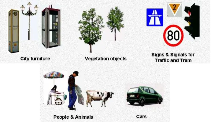
CityGML defines the classes and relations for the most relevant topographic objects in cities and regional mod-els with respect to their geometrical, topological, semantical, and appearance properties. “City” is broadly
defined to comprise not just built structures, but also elevation, vegetation, water bodies, “city furniture”, and
more. Included are generalisation hierarchies between thematic classes, aggregations, relations between objects, and spatial properties. CityGML is applicable for large areas and small regions and can represent the terrain and 3D objects in different levels of detail simultaneously. Since either simple, single scale models without topology and few semantics or very complex multi-scale models with full topology and fine-grained semantical differenti-ations can be represented, CityGML enables lossless information exchange between different GI systems and users.
0.2
Historical background
CityGML has been developed since 2002 by the members of the Special Interest Group 3D (SIG 3D). Since 2010, this group is part of the initiative Spatial Data Infrastructure Germany (GDI-DE). Before 2010, the SIG 3D was affiliated to the initiative Geodata Infrastructure North Rhine-Westphalia (GDI NRW). The SIG 3D is an open group consisting of more than 70 companies, municipalities, and research institutions from Germany, Great Britain, Switzerland, and Austria working on the development and commercial exploitation of interoperable 3D city models and geovisualisation. Another result of the work from the SIG 3D is the proposition of the Web 3D Service (W3DS), a 3D portrayal service that is also being discussed in the Open Geospatial Consortium (OGC Doc. No. 05-019 and OGC Doc. No. 09-104r1).
Copyright © 2012 Open Geospatial Consortium. xv From that point in time, CityGML has disseminated worldwide. Many cities in Germany and in other countries in Europe provide their 3D city model in CityGML (Berlin, Cologne, Dresden and Munich, to mention only a few). In France, the project Bâti3D (IGN France) defines a profile of CityGML LOD2 and provides data from Paris and the city centres of Aix-en-Provence, Lille, Nantes and Marseille. CityGML also plays an important role in the pilot 3D project to obtain a 3D geoinformation standard and a 3D infrastructure for The Netherlands. Many cities in Europe like Monaco, Geneva, Zurich, Leewarden use CityGML LOD 2 or 3 to represent and exchange data, as well as cities in Denmark (LOD 2 and 3, partly LOD4). CityGML has strongly influenced the building model (version 2.0) of the INSPIRE initiative of the EU commission, which aims at the creation of an European spatial data infrastructure providing public sector data in an interoperable way. In Asia, the 3D city models of Istanbul (LOD 1 and 2), Doha, Katar (LOD3), and Yokohama (LOD2) are represented and exchanged in CityGML. Moreover, CityGML plays a crucial role for the 3D Spatial data infrastructure in Malaysia.
Today many commercial and academic tools support CityGML by providing import interfaces, export interfaces or both. An example is the 3D City Database which is a free and open source 3D geo database to store, represent, and manage virtual 3D city models on top of Oracle 10g R2 and 11g R1/R2 provided by the Technische Univer-sität Berlin. It fully supports CityGML and is shipped with a tool for the import and export of CityGML models. Furthermore, an open source Java class library and API for the processing of CityGML models (citygml4j) is provided by the Technische Universität Berlin. The conversion tool FME (Feature Manipulation Engine) from
Safe Software Inc., which is part of the interoperability extension of ESRI’s ArcGIS, has read and write interfa
c-es for CityGML. The same applic-es to CAD tools as BentleyMap from Bentley Systems as well as to GIS tools like SupportGIS from CPA Geo-Information. Many 3D viewers (which all are freely available) provide read interfaces for CityGML: the Aristoteles Viewer from the University of Bonn, LandXplorer CityGML Viewer from Autodesk Inc. (the studio version for authoring and management is not free) and the FZKViewer for IFC and CityGML from KIT Karlsruhe and BS Contact from Bitmanagement Software GmbH which offers a CityGML plugin for the geospatial extension BS Contact Geo. This enumeration of software tools is not
exhaus-tive and steadily growing. Please refer to the official website of CityGML at http://www.citygml.org as well as
the CityGML Wiki at http://www.citygmlwiki.org for more information.
0.3
Additions in CityGML 2.0
CityGML 2.0 is a major revision of the previous version 1.0 of this International Standard (OGC Doc. No. 08-007r1), and introduces substantial additions and new features to the thematic model of CityGML. The revision was originally planned to be a minor update to version 1.1. The main endeavor of the revision process was to ensure backwards compatibility both on the level of the conceptual model and on the level of CityGML instance documents. However, some changes could not be implemented consistent with directives for minor revisions and backwards compatibility as enforced by OGC policy (cf. OGC Doc. No. 135r11). The major version number change to 2.0 is therefore a consequence of conforming to the OGC versioning policy without having to abandon any changes or additions which reflect requests from the CityGML community.
CityGML 2.0 is backwards compatible with version 1.0 in the following sense: each valid 1.0 instance is a valid 2.0 instance provided that the CityGML namespaces and schema locations in the document are changed to their actual 2.0 values. This step is required because the CityGML version number is encoded in these values, but no further actions have to be taken. Hence, there is a simple migration path from existing CityGML 1.0 instances to valid 2.0 instances.
The following clauses provide an overview of what is new in CityGML 2.0.
New thematic modules for the representation of bridges and tunnels
Bridges and tunnels are important objects in city and landscape models. They are an essential part of the trans-portation infrastructure and are often easily recognizable landmarks of a city. CityGML 1.0 has been lacking thematic modules dedicated to bridges and tunnels, and thus such objects had to be modelled and exchanged using a GenericCityObject as proxy (cf. chapter 10.12). CityGML 2.0 now introduces two new thematic modules for the explicit representation of bridges and tunnels which complement the thematic model of CityGML: the Bridge module (cf. chapter 10.4) and the Tunnel module (cf. chapter 10.5).
Bridges and tunnels can be represented in LOD 1 – 4 and the underlying data models have a coherent structure
interi-xvi Copyright © 2012 Open Geospatial Consortium. or built structures can be represented. This coherent model structure facilitates the similar understanding of semantic entities and helps to reduce software implementation efforts. Both the Bridge and the Tunnel model introduce further concepts and model elements which are specific to bridges and tunnels respectively.
Additions to existing thematic modules
CityGML Core module (cf. chapter 10.1)
Two new optional attributes have been added to the abstract base class core:_CityObject within the
CityGML Core module: relativeToTerrain and relativeToWater. These attributes denote the feature’s
location with respect to the terrain and water surface in a qualitative way, and thus facilitate simple and efficient queries (e.g., for the number of subsurface buildings) without the need for an additional digital terrain model or a model of the water body.
Building module (cf. chapter 10.3)
o LOD0 representation
Buildings can now be represented in LOD0 by footprint and/or roof edge polygons. This al-lows the easy integration of existing 2D data and of roof reconstructions from aerial and satel-lite imagery into a 3D city model. The representations are restricted to horizontal, 3-dimensional surfaces.
o Additional thematic boundary surfaces
In order to semantically classify parts of the outer building shell which are neither horizontal wall surfaces nor parts of the roof, two additional boundary surfaces are introduced: OuterFloorSurface and OuterCeilingSurface.
o Additional relations to thematic boundary surfaces
In addition to _AbstractBuilding and Room, the surface geometries of BuildingInstallation and IntBuildingInstallation features can now be semantically classified using thematic boundary surfaces. For example, this facilitates the semantic differentiation between roof and wall sur-faces of dormers which are modeled as BuildingInstallation.
o Additional use of implicit geometries
Implicit geometries (cf. chapter 8.3) are now available for the representation of _Opening, BuildingInstallation, and IntBuildingInstallation in addition to BuildingFurniture. A prototyp-ical geometry for these city objects can thus be stored once and instantiated at different loca-tions in the 3D city model.
Generics module (cf. chapter 10.12)
Two generic attributes have been added to the Generics module: MeasureAttribute and GenericAttributeSet. A MeasureAttribute facilitates the representation of measured values together with a reference to the employed unit. A GenericAttributeSet is a named collection of arbitrary generic at-tributes. It provides an optional codeSpace attribute to denote the authority organization who defined the attribute set.
LandUse module (cf. chapter 10.10)
The scope of the feature type LandUse has been broadened to comprise both areas of the earth’s surface
dedicated to a specific land use and areas of the earth’s surface having a specific land cover with or without vegetation.
Attributes class, function, and usage (all modules)
In order to harmonize the use of the attributes class, function, and usage, this attribute triplet has been complemented for all feature classes that at least provided one of the attributes in CityGML 1.0.
Additions to the CityGML code list mechanism
Copyright © 2012 Open Geospatial Consortium. xvii chapter 10.14 for more information). The gml:CodeType adds an optional codeSpace value to enumerative attributes which allows for providing a persistent URI pointing to the corresponding dictionary.
Changelog for CityGML 2.0
Changes on the level of XML schema components are provided in Annex F.
Further edits to the specification document
Accuracy requirements for Levels of Detail (LOD) (cf. chapter 6.2)
The accuracy requirements for the different CityGML LODs proposed in chapter 6.2 are non-normative. The wording of chapter 6.2 in CityGML 1.0 is however inconsistent with regard to this fact and thus has been clarified for CityGML 2.0.
Rework of the CityGML example datasets (cf. Annex G)
The CityGML examples provided in Annex G have been reworked and extended. They now show a consistent building model in all five LODs and demonstrate, for example, the semantic and geometric refinement of the building throughout the different LODs as well as the usage of XLinks to share geom-etry elements between features. The datasets are shipped with the CityGML XML Schema package, and are available at http://schemas.opengis.net/citygml/examples/2.0/.
New example for the usage of Application Domain Extensions (cf. Annex I)
Copyright © 2012 Open Geospatial Consortium. 1
OGC® City Geography Markup Language (CityGML)
Encoding Standard
1
Scope
This document is an OGC Encoding Standard for the representation, storage and exchange of virtual 3D city and landscape models. CityGML is implemented as an application schema of the Geography Markup Language version 3.1.1 (GML3).
CityGML models both complex and georeferenced 3D vector data along with the semantics associated with the data. In contrast to other 3D vector formats, CityGML is based on a rich, general purpose information model in addition to geometry and appearance information. For specific domain areas, CityGML also provides an exten-sion mechanism to enrich the data with identifiable features under preservation of semantic interoperability.
Targeted application areas explicitly include urban and landscape planning; architectural design; tourist and leisure activities; 3D cadastres; environmental simulations; mobile telecommunications; disaster management; homeland security; vehicle and pedestrian navigation; training simulators and mobile robotics.
CityGML is considered a source format for 3D portraying. The semantic information contained in the model can be used in the styling process which generates computer graphics represented e.g. as KML/COLLADA or X3D files. The appropriate OGC Portrayal Web Service for this process is the OGC Web 3D Service (W3DS). An image-based 3D portrayal service for virtual 3D landscape and city models is provided by the OGC Web View Service (WVS).
Features of CityGML:
Geospatial information model (ontology) for urban landscapes based on the ISO 191xx family
GML3 representation of 3D geometries, based on the ISO 19107 model
Representation of object surface characteristics (e.g. textures, materials)
Taxonomies and aggregations
o Digital Terrain Models as a combination of (including nested) triangulated irregular networks
(TINs), regular rasters, break and skeleton lines, mass points
o Sites (currently buildings, bridges, and tunnels)
o Vegetation (areas, volumes, and solitary objects with vegetation classification)
o Water bodies (volumes, surfaces)
o Transportation facilities (both graph structures and 3D surface data)
o Land use (representation of areas of the earth’s surface dedicated to a specific land use)
o City furniture
o Generic city objects and attributes
o User-definable (recursive) grouping
Multiscale model with 5 well-defined consecutive Levels of Detail (LOD):
o LOD0 – regional, landscape
o LOD1 – city, region
o LOD2 – city districts, projects
o LOD3 – architectural models (outside), landmarks
o LOD4 – architectural models (interior)
Multiple representations in different LODs simultaneously; generalisation relations between objects in
different LODs
Optional topological connections between feature (sub)geometries
Application Domain Extensions (ADE): Specific “hooks” in the CityGML schema allow to define a
2 Copyright © 2012 Open Geospatial Consortium.
2
Conformance
Conformance targets addressed by this International standard are CityGML instance documents only. Future revisions of this International Standard may also address consumers or producers as conformance targets.
Clauses 8 to 10 of this International standard specify separate CityGML XML Schema definitions and normative aspects, i.e. CityGML modules, which shall be used in CityGML instance documents in accordance with clause 7. Implementations are not required to support the full range of capabilities provided by the universe of all CityGML modules. Valid partial implementations are supported following the rules and guidelines for CityGML profiles in chapter 7.2.
CityGML instance documents claiming conformance to this International Standard shall:
a) conform to the rules and requirements specified in clauses 7 to 10;
b) pass all relevant test cases of the abstract test suite in annex B.1;
c) satisfy all relevant conformance classes of the abstract test suite related to CityGML modules in annex
B.2.
3
Normative references
The following normative documents contain provisions which, through reference in this text, constitute provi-sions of this part of OGC 12-019. For dated references, subsequent amendments to, or reviprovi-sions of, any of these publications do not apply. However, parties to agreements based on this part of OGC 12-019 are encouraged to investigate the possibility of applying the most recent editions of the normative documents indicated below. For undated references, the latest edition of the normative document referred to applies.
The following documents are indispensable for the application of the CityGML standard. The geometry model of GML 3.1.1 is used except for some added concepts like implicit geometries (cf. chapter 8.2). The appearance model (cf. chapter 9) draws concepts from both X3D and COLLADA. Addresses are represented using the OASIS extensible Address Language xAL.
ISO 8601:2004, Data elements and interchange formats – Information interchange – Representation of dates and times
ISO/TS 19103:2005, Geographic Information – Conceptual Schema Language
ISO 19105:2000, Geographic information – Conformance and testing
ISO 19107:2003, Geographic Information – Spatial Schema
ISO 19109:2005, Geographic Information – Rules for Application Schemas
ISO 19111:2003, Geographic information – Spatial referencing by coordinates
ISO 19115:2003, Geographic Information – Metadata
ISO 19123:2005, Geographic Information – Coverages
ISO/TS 19139:2007, Geographic Information – Metadata – XML schema implementation
ISO/IEC 19775:2004, X3D Abstract Specification
OpenGIS® Abstract Specification Topic 0, Overview, OGC document 04-084
OpenGIS® Abstract Specification Topic 5, The OpenGIS Feature, OGC document 99-105r2
OpenGIS® Abstract Specification Topic 8, Relations between Features, OGC document 99-108r2
OpenGIS® Abstract Specification Topic 10, Feature Collections, OGC document 99-110
OpenGIS® Geography Markup Language Implementation Specification, Version 3.1.1, OGC document 03-105r1
OpenGIS® GML 3.1.1 Simple Dictionary Profile, Version 1.0.0, OGC document 05-099r2
IETF RFC 2045 & 2046, Multipurpose Internet Mail Extensions (MIME). (November 1996)
IETF RFC 2396, Uniform Resource Identifiers (URI): Generic Syntax. (August 1998)
Copyright © 2012 Open Geospatial Consortium. 3 W3C XMLName, Namespaces in XML. W3C Recommendation (14 January 1999)
W3C XMLSchema-1, XML Schema Part 1: Structures. W3C Recommendation (2 May 2001)
W3C XMLSchema-2, XML Schema Part 2: Datatypes. W3C Recommendation (2 May 2001)
W3C XPointer, XML Pointer Language (XPointer) Version 1.0. W3C Working Draft (16 August 2002)
W3C XML Base, XML Base, W3C Recommendation (27 June 2001)
W3C XML, Extensible Markup Language (XML) 1.0 (Second Edition), W3C Recommendation (6 October 2000)
OASIS (Organization for the Advancement of Structured Information Standards): extensible Address Language (xAL v2.0).
Khronos Group Inc.: COLLADA – Digital Asset Schema Release 1.4.1
The Schematron Assertion Language 1.5. Rick Jelliffe 2002-10-01
4
Conventions
4.1
Abbreviated terms
The following abbreviated terms are used in this document:
2D Two Dimensional
3D Three Dimensional
AEC Architecture, Engineering, Construction
ALKIS German National Standard for Cadastral Information
ATKIS German National Standard for Topographic and Cartographic Information
B-Rep Boundary Representation
bSI buildingSMART International
CAD Computer Aided Design
COLLADA Collaborative Design Activity
CSG Constructive Solid Geometry
DTM Digital Terrain Model
DXF Drawing Exchange Format
EuroSDR European Spatial Data Research Organisation
ESRI Environmental Systems Research Institute
FM Facility Management
GDF Geographic Data Files
GDI-DE Spatial Data Infrastructure Germany (Geodateninfrastruktur Deutschland)
GDI NRW Geodata Infrastructure North-Rhine Westphalia
GML Geography Markup Language
IAI International Alliance for Interoperability (now buildingSMART International (bSI))
IETF Internet Engineering Task Force
IFC Industry Foundation Classes
ISO International Organization for Standardisation
LOD Level of Detail
NBIMS National Building Information Model Standard
OASIS Organisation for the Advancement of Structured Information Standards
OGC Open Geospatial Consortium
4 Copyright © 2012 Open Geospatial Consortium.
SIG 3D Special Interest Group 3D of the GDI-DE
TC211 ISO Technical Committee 211
TIC Terrain Intersection Curve
TIN Triangulated Irregular Network
UML Unified Modeling Language
URI Uniform Resource Identifier
VRML Virtual Reality Modeling Language
W3C World Wide Web Consortium
W3DS OGC Web 3D Service
WFS OGC Web Feature Service
X3D Open Standards XML-enabled 3D file format of the Web 3D Consortium
XML Extensible Markup Language
xAL OASIS extensible Address Language
4.2
UML Notation
The CityGML standard is presented in this document in diagrams using the Unified Modeling Language (UML) static structure diagram (see Booch et al. 1997). The UML notations used in this standard are described in the diagram below (Fig. 1).
Fig. 1: UML notation (see ISO TS 19103, Geographic information - Conceptual schema language).
Copyright © 2012 Open Geospatial Consortium. 5 The following stereotypes are used:
<<Geometry>> represents the geometry of an object. The geometry is an identifiable and distinguishable object that is derived from the abstract GML type AbstractGeometryType.
<<Feature>> represents a thematic feature according to the definition in ISO 19109. A feature is an identifiable and distinguishable object that is derived from the abstract GML type AbstractFeatureType.
<<Object>> represents an identifiable and distinguishable object that is derived from the abstract GML type AbstractGMLType.
<<Enumeration>> enumerates the valid attribute values in a fixed list of named literal values. Enumerations are specified inline the CityGML schema.
<<CodeList>> enumerates the valid attribute values. In contrast to Enumeration, the list of values is open and, thus, not given inline the CityGML schema. The allowed values can be provided within an external code list. It is recommended that code lists are implemented as simple dictionaries following the GML 3.1.1 Simple Dictionary Profile (cf. chapter 6.6 and chapter 10.14).
<<Union>> is a list of attributes. The semantics are that only one of the attributes can be present at any time.
<<PrimitiveType>> is used for representations supported by a primitive type in the implementation.
<<DataType>> is used as a descriptor of a set of values that lack identity. Data types include primitive prede-fined types and user-definable types. A DataType is thus a class with few or no operations whose primary purpose is to hold the abstract state of another class for transmittal, storage, encoding or persistent storage.
<<Leaf>> is used within UML package diagrams to indicate model elements that can have no further subtypes.
<<XSDSchema>> is used within UML package diagrams to denote the root element of an XSD Schema contain-ing all the definitions for a particular namespace. All the package contents or component classes are placed within the one schema.
<<ApplicationSchema>> is used within UML package diagrams to denote an XML Schema definition funda-mentally dependent on the concepts of another independent Standard within the XML Schema
metalan-guage. For example, ApplicationSchema indicates extensions of GML consistent with the GML “rules for
application schemas”.
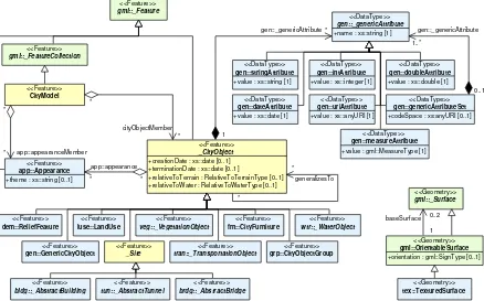
In order to enhance the readability of the CityGML UML diagrams, classes are depicted in different colors if they belong to different UML packages (see Fig. 8 for an overview of UML packages). The following coloring scheme is applied:
Classes painted in yellow belong to the UML package which is subject of discussion in that clause of
the specification in which the UML diagram is given. For example, in the context of chapter 10.1 which introduces the CityGML Core module, the yellow color is used to denote classes which are de-fined in the CityGML Core UML package. Likewise, the yellow classes shown in UML diagrams in chapter 10.3 are associated with the Building module which is subject of discussion in that chapter.
Classes painted in blue belong to a CityGML UML package different to that associated with the yellow
color. In order to explicitly denote the UML package of such classes, their class names carry a namespace prefix which is uniquely associated with a CityGML module throughout this specification (cf. section 4.3 for a list of namespaces and prefixes). For example, in the context of the Building mod-ule, classes from the CityGML Core module are painted in blue and their class names are preceded by the prefix core.
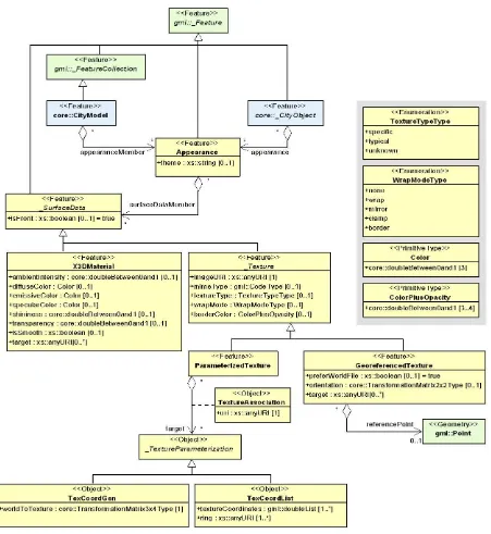
6 Copyright © 2012 Open Geospatial Consortium. The following example UML diagram demonstrates the UML notation and coloring scheme used throughout this specification. In this example, the yellow classes are associated with the CityGML Building module, the blue classes are from the CityGML Core module, and the green class depicts a geometry element defined by GML3.
Fig. 2: Example UML diagram demonstrating the UML notation and coloring scheme used throughout the CityGML specification.
4.3
XML namespaces and namespace prefixes
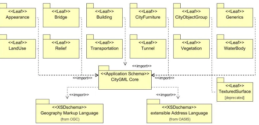
The CityGML data model is thematically decomposed into a core module and thematic extension modules. All modules including the core are specified by their own XML schema file, each defining a globally unique XML namespace. The extension modules are based on the core module and, thus, contain (by reference) the CityGML core schema.
Within this document the module namespaces are associated with recommended prefixes. These prefixes are consistently used within the normative parts of this specification, for all UML diagrams and example CityGML instance documents. The CityGML core and extension modules along with their XML namespace identifiers and recommended namespace prefixes are listed in Tab. 1.
CityGML module Namespace identifier Namespace prefix
CityGML Core http://www.opengis.net/citygml/2.0 core
Appearance http://www.opengis.net/citygml/appearance/2.0 app
Bridge http://www.opengis.net/citygml/bridge/2.0 brid
Building http://www.opengis.net/citygml/building/2.0 bldg
CityFurniture http://www.opengis.net/citygml/cityfurniture/2.0 frn
CityObjectGroup http://www.opengis.net/citygml/cityobjectgroup/2.0 grp
Generics http://www.opengis.net/citygml/generics/2.0 gen
LandUse http://www.opengis.net/citygml/landuse/2.0 luse
Relief http://www.opengis.net/citygml/relief/2.0 dem
Transportation http://www.opengis.net/citygml/transportation/2.0 tran
Tunnel http://www.opengis.net/citygml/tunnel/2.0 tun
Vegetation http://www.opengis.net/citygml/vegetation/2.0 veg
WaterBody http://www.opengis.net/citygml/waterbody/2.0 wtr
TexturedSurface [deprecated] http://www.opengis.net/citygml/texturedsurface/2.0 tex
Tab. 1: List of CityGML modules, their associated XML namespace identifiers, and example namespace prefixes.
<<Feature>> _AbstractBuilding
<<Feature>> Building
<<Feature>> BuildingPart <<Feature>>
core::_CityObject
<<Feature>> core::_Site
<<Geometry>> gml::_Solid
*
* *
* *
consistsOfBuildingPart 0..1
* lod4Solid
lod1Solid
lod2Solid
Copyright © 2012 Open Geospatial Consortium. 7 Further XML Schema definitions relevant to this standard are shown in Tab. 2 along with the corresponding XML namespace identifiers and namespace prefixes consistently used within this document.
XML Schema definition Namespace identifier Namespace prefix
Geography Markup Language version 3.1.1 (from OGC)
http://www.opengis.net/gml gml
Extensible Address Language version 2.0 (from OASIS)
urn:oasis:names:tc:ciq:xsdschema:xAL:2.0 xAL
Schematron Assertion Lan-guage version 1.5
http://www.ascc.net/xml/schematron sch
Tab. 2: List of XML Schema definitions, their associated XML namespace identifiers, and example namespace prefixes used within this document.
4.4
XML-Schema
Copyright © 2012 Open Geospatial Consortium. 9
5
Overview of CityGML
CityGML is an open data model and XML-based format for the storage and exchange of virtual 3D city models. It is an application schema for the Geography Markup Language version 3.1.1 (GML3), the extendible interna-tional standard for spatial data exchange issued by the Open Geospatial Consortium (OGC) and the ISO TC211.
The aim of the development of CityGML is to reach a common definition of the basic entities, attributes, and relations of a 3D city model. This is especially important with respect to the cost-effective sustainable mainte-nance of 3D city models, allowing the reuse of the same data in different application fields.
CityGML not only represents the graphical appearance of city models but specifically addresses the representa-tion of the semantic and thematic properties, taxonomies and aggregarepresenta-tions. CityGML includes a geometry model and a thematic model. The geometry model allows for the consistent and homogeneous definition of geometrical and topological properties of spatial objects within 3D city models (chapter 8). The base class of all objects is _CityObject which is a subclass of the GML class _Feature. All objects inherit the properties from _CityObject.
The thematic model of CityGML employs the geometry model for different thematic fields like Digital Terrain Models, sites (i.e. buildings, bridges, and tunnels), vegetation (solitary objects and also areal and volumetric biotopes), land use, water bodies, transportation facilities, and city furniture (chapter 10). Further objects, which are not explicitly modelled yet, can be represented using the concept of generic objects and attributes (chapter 6.11). In addition, extensions to the CityGML data model applying to specific application fields can be realised using the Application Domain Extensions (ADE) (chapter 6.12). Spatial objects of equal shape which appear many times at different positions like e.g. trees, can also be modelled as prototypes and used multiple times in the city model (chapter 8.2). A grouping concept allows the combination of single 3D objects, e.g. buildings to a building complex (chapter 6.8). Objects which are not geometrically modelled by closed solids can be virtually sealed in order to compute their volume (e.g. pedestrian underpasses, tunnels, or airplane hangars). They can be closed using ClosureSurfaces (chapter 6.4). The concept of the TerrainIntersectionCurve is introduced to inte-grate 3D objects with the Digital Terrain Model at their correct positions in order to prevent e.g. buildings from floating over or sinking into the terrain (chapter 6.5).
CityGML differentiates five consecutive Levels of Detail (LOD), where objects become more detailed with increasing LOD regarding both their geometry and thematic differentiation (chapter 6.2). CityGML files can - but do not have to - contain multiple representations (and geometries) for each object in different LOD simulta-neously. Generalisation relations allow the explicit representation of aggregated objects over different scales.
In addition to spatial properties, CityGML features can be assigned appearances. Appearances are not limited to
visual data but represent arbitrary observable properties of the feature’s surface such as infrared radiation, noise
pollution, or earthquake-induced structural stress (chapter 9).
Copyright © 2012 Open Geospatial Consortium. 11
6
General characteristics of CityGML
6.1
Modularisation
The CityGML data model consists of class definitions for the most important types of objects within virtual 3D city models. These classes have been identified to be either required or important in many different application areas. However, implementations are not required to support the overall CityGML data model in order to be conformant to the standard, but may employ a subset of constructs according to their specific information needs. For this purpose, modularisation is applied to the CityGML data model (cf. chapter 7).
The CityGML data model is thematically decomposed into a core module and thematic extension modules. The core module comprises the basic concepts and components of the CityGML data model and, thus, must be implemented by any conformant system. Based on the core module, each extension covers a specific thematic field of virtual 3D city models. CityGML introduces the following thirteen thematic extension modules: Appear-ance, Bridge, Building, CityFurniture, CityObjectGroup, Generics, LandUse, Relief, Transportation, Tunnel, Vegetation, WaterBody, and TexturedSurface [deprecated] .
CityGML compliant implementations may support any combination of extension modules in conjunction with the core module. Such combinations of modules are called CityGML profiles. Therefore, CityGML profiles allow for valid partial implementations of the overall CityGML data model.
6.2
Multi-scale modelling (5 levels of detail, LOD)
CityGML supports different Levels of Detail (LOD). LODs are required to reflect independent data collection processes with differing application requirements. Further, LODs facilitate efficient visualisation and data analysis (see Fig. 3). In a CityGML dataset, the same object may be represented in different LOD simultaneous-ly, enabling the analysis and visualisation of the same object with regard to different degrees of resolution. Furthermore, two CityGML data sets containing the same object in different LOD may be combined and inte-grated. However, it will be within the responsibility of the user or application to make sure objects in different LODs refer to the same real-world object.
The coarsest level LOD0 is essentially a two and a half dimensional Digital Terrain Model over which an aerial image or a map may be draped. Buildings may be represented in LOD0 by footprint or roof edge polygons. LOD1 is the well-known blocks model comprising prismatic buildings with flat roof structures. In contrast, a building in LOD2 has differentiated roof structures and thematically differentiated boundary surfaces. LOD3 denotes architectural models with detailed wall and roof structures potentially including doors and windows. LOD4 completes a LOD3 model by adding interior structures for buildings. For example, buildings in LOD4 are composed of rooms, interior doors, stairs, and furniture. In all LODs appearance information such as high-resolution textures can be mapped onto the structures (cf. 6.9).
LOD0 LOD1 LOD2
LOD3 LOD4
12 Copyright © 2012 Open Geospatial Consortium. LODs are also characterised by differing accuracies and minimal dimensions of objects (cf. Tab. 3). The accura-cy requirements given in this standard are debatable and are to be considered as discussion proposals. Accuraaccura-cy is described as standard deviation of the absolute 3D point coordinates. Relative 3D point accuracy will be added in a future version of CityGML and it is typically much higher than the absolute accuracy. In LOD1, the positional and height accuracy of points should be 5m or less, while all objects with a footprint of at least 6m by 6m should be considered. The positional and height accuracy of LOD2 is proposed to be 2m or better. In this LOD, all objects with a footprint of at least 4m × 4m should be considered. Both types of accuracies in LOD3 should be 0.5m, and the minimal footprint is suggested to be 2m × 2m. Finally, the positional and height accura-cy of LOD4 should be 0.2m or less. By means of these figures, the classification in five LOD may be used to assess the quality of 3D city model datasets. The LOD categorisation makes datasets comparable and provides support for their integration.
LOD0 LOD1 LOD2 LOD3 LOD4
Model scale description regional,
landscape
city, region city, city districts,
projects
Building installations no no yes representative
exterior features
real object form
Roof structure/representation yes flat differentiated roof
structures
real object form real object form
Roof overhanging parts yes no yes, if known yes yes
CityFurniture no important objects prototypes,
gener-alized objects
real object form real object form
SolitaryVegetationObject no important objects prototypes, higher
6m
…to be continued for the other feature themes
Tab. 3: LOD 0-4 of CityGML with their proposed accuracy requirements (discussion proposal, based on: Albert et al. 2003).
Whereas in CityGML each object can have a different representation for every LOD, often different objects from the same LOD will be generalised to be represented by an aggregate object in a lower LOD. CityGML supports the aggregation / decomposition by providing an explicit generalisation association between city objects (further details see UML diagram in chapter 10.1).
6.3
Coherent semantical-geometrical modelling
One of the most important design principles for CityGML is the coherent modelling of semantics and geomet-rical/topological properties. At the semantic level, real-world entities are represented by features, such as build-ings, walls, windows, or rooms. The description also includes attributes, relations and aggregation hierarchies (part-whole-relations) between features. Thus the part-of-relationship between features can be derived at the semantic level only, without considering geometry. However, at the spatial level, geometry objects are assigned to features representing their spatial location and extent. So the model consists of two hierarchies: the semantic and the geometrical in which the corresponding objects are linked by relationships (cf. Stadler & Kolbe 2007). The advantage of this approach is that it can be navigated in both hierarchies and between both hierarchies arbitrarily, for answering thematic and/or geometrical queries or performing analyses.
If both hierarchies exist for a specific object, they must be coherent (i.e. it must be ensured that they match and fit together). For example, if a wall of a building has two windows and a door on the semantic level, then the geometry representing the wall must contain also the geometry parts of both windows and the door.
6.4
Closure surfaces
Copyright © 2012 Open Geospatial Consortium. 13 special surfaces, which are taken into account, when needed to compute volumes and are neglected, when they are irrelevant or not appropriate, for example in visualisations.
The concept of ClosureSurface is also employed to model the entrances of subsurface objects. Those objects like tunnels or pedestrian underpasses have to be modelled as closed solids in order to compute their volume, for example in flood simulations. The entrances to subsurface objects also have to be sealed to avoid holes in the digital terrain model (see Fig. 4). However, in close-range visualisations the entrance must be treated as open. Thus, closure surfaces are an adequate way to model those entrances.
Fig. 4: Closure surfaces to seal open structures. Passages are subsurface objects (left). The entrance is sealed by a virtual
ClosureSurface, which is both part of the DTM and the subsurface object (right) (graphic: IGG Uni Bonn).
6.5
Terrain Intersection Curve (TIC)
A crucial issue in city modelling is the integration of 3D objects and the terrain. Problems arise if 3D objects float over or sink into the terrain. This is particularly the case if terrains and 3D objects in different LOD are combined, or if they come from different providers (Kolbe and Gröger 2003). To overcome this problem, the TerrainIntersectionCurve (TIC) of a 3D object is introduced. These curves denote the exact position, where the terrain touches the 3D object (see Fig. 5). TICs can be applied to buildings and building parts (cf. chapter 10.3), bridge, bridge parts and bridge construction elements (cf. chapter 10.5), tunnel and tunnel parts (cf. chapter 10.4), city furniture objects (cf. chapter 10.9), and generic city objects (cf. chapter 10.12). If, for example, a building has a courtyard, the TIC consists of two closed rings: one ring representing the courtyard boundary, and one which describes the building's outer boundary. This information can be used to integrate the building and a
terrain by ‘pulling up’ or ‘pulling down’ the surrounding terrain to fit the TerrainIntersectionCurve. The DTM
may be locally warped to fit the TIC. By this means, the TIC also ensures the correct positioning of textures or the matching of object textures with the DTM. Since the intersection with the terrain may differ depending on the LOD, a 3D object may have different TerrainIntersectionCurves for all LOD.
Fig. 5: TerrainIntersectionCurvefor a building (left, black) and a tunnel object (right, white). The tunnel’s hollow space is sealed by a