HUMBOLDT-UNIVERSITÄT ZU BERLIN
INSTITUT FÜR INFORMATIK
COMPUTER ARCHITECTURE
Lecture 11
ALU (2) - Integer Arithmetic
Sommersemester 2001
Leitung: Prof. Dr. Miroslaw Malek
ALU
ARITHMETIC-LOGIC UNIT
Arithmetic Units Classification Number representations
Hardware/software continuum and vertical migration
Integer Arithmetic
Addition/subtraction Multiplication
Booth's Algorithm Bit Pair Algorithm Division
ADDITION/SUBTRACTION OF POSITIVE AND
NEGATIVE NUMBERS
- Sign & Magnitude (awkward +,-)
- 1's complement (better). Requires a correct cycle
- 2's complement is awkward externally, but is the best hardware representation for addition and subtraction
n C t
S t
a) 2's Complement Addition
(1) Modulo Arithmetic
Positive Numbers 7 + 4 = 11 no change Negative Numbers -7 + (-4) = -11
2's complement (9 + 12) = 21 which is -11 in signed decimal notation
In general (X + Y) mod 2n
2's complement (9+12) mod 16 = 5 which is also 11 in decimal Add 2's complement using adder as in the figure.
Ignore carry-out bit and you have a correct answer.
(2) Numbers outside the expected range cause an arithmetic overflow.
b) Subtraction
Subtraction is the same as performing addition of a complement. 7-4=3 is equivalent 7+12=19
in 2's complement which is 3 after ignoring the carry.
− +
< < −
OVERFLOW
cn = 1, X + Y
≥
2nOverflow is only possible when both operands have the same sign.
Overflow occurs when the sign of S does not agree with the signs of X and Y, i.e., when the signs of X and Y are the same.
Overflow = xn-1yn-1sn-1 + xn-1yn-1sn-1
MULTIPLICATION
"PAPER AND PENCIL METHOD"
1 1 0 1 x 1 0 1 1 1 1 0 1 1 1 0 1 0 0 0 0
1 1 0 1
1 0 0 0 1 1 1 1
(13) Multiplicand M (11) Multiplier Q
(143) Product P
q 3 0
PP4 = product
p 7 p 6 p 5 p 4 p 3
P P 3
P P 2
P P 1 Partial Product 0 (PP0)
0 m 3 0 m 2 0 m 1 0 m 0
TYPICAL CELL OF MULTIPLICATION ARRAY
IMPLEMENTATION
m
j
q
i
A
Sum
Bit of incoming partial product (PPi)
Carry-in Carry-out
REGISTER CONFIGURATION FOR SEQUENTIAL CIRCUIT
BINARY MULTIPLIER
C
0
A register (initially 0)
SHIFT RIGHT
an-1 a0 qn-1 q0
Multiplier Q
1 → ADD 0 → NO ADD
ADD/NO ADD n-bit
adder
Multiplicand M
mn-1 m0
MULTIPLICATION EXAMPLE
M 1 1 0 1
0 0 0 0 1 0 1 1
A Q
1 1 0 1 0 1 1 0
0 0 1 1 1 0 0 1
1 0 0 1 0 1 0 0
0 0 0 1 1 0 0 0
1 0 1 1 1 1 0 1
1 1 0 1 1 1 1 0
1 1 1 0 1 1 1 1
1 1 1 1 1 1 1 1 0 0 1 0 0 0 1 0 0 C
PP0 is in A after the first ADD
FLOWCHART FOR 2'S-COMPLEMENT MULTIPLICATION
Start
Q(7) = 0?
Stop COUNT = 7?
No
Yes
No Yes
A A + M
COUNT COUNT+1
A(1:n-1),Q A,Q(0:n - 2)
R
0 1 7
A(0) A(0)
... ... A ← 0
COUNT← 0 V ← 0
M← multiplicand
Q ← multiplier
OUTBUS A
OUTBUS Q(0:n-1)
A(0) M(0) Q(7)
BLOCK DIAGRAM OF 2'S-COMPLEMENT FIXED-POINT
MULTIPLIER
Control unit
Accumulator Multiplier Multiplicand
A Q M
A(0) C 2 C10 C 1 C 4 C 3 C10 V Overflow flip-flop
C 6 C1
C 8
Q(7) C 5
PDP-11 REGISTER ARRANGEMENT FOR
SOFTWARE MULTIPLY
R0 C
Ri R0
R2 C
0
MULTIPLIER Q R1
SHIFT LEFT A register (initially 0)
MSB LSB
C
ASL R0 ROL RI
Long Shift Left
Ri:R0
MULTIPLICAND M 2
SOFTWARE MULTIPLICATION
CLR R0 Clear register R0
MOV #-16.,R3 Set register R3 to -16 → use as cycle counter
mloop:
ASL R0 ASL (Arithmetic Shift Left) instruction shifts contents of R0 (low-order half of
partial product) left one bit. MSB of R0 is shifted into C bit. LSB of R0 is set to 0
ROL R1 ROL (Rotate Left) instruction rotates contents of R1 and the C bit by one bit
position. Old contents of C is moved into LSB of R1, old contents of MSB of R1 is moved into C.
The combination of ASL and ROL have thus shifted the (R1, R0) pair left one bit position, placing the old MSB of R1 into C.
BCC noadd The multiplier bit to be checked (first qn-1, then qn-, etc.) is now in C, and the
instruction BCC causes a branch around the add operation if C is 0.
ADD R2,R0 If C=1, multiplicand in R2 is added into the low-order end of the partial product
in R0. Any carry-out that goes into C must be added to the high-order half of
ADC R1 the partial product. This is done by the ADC which adds contents of C to the
LSB position of R1. Note that this process will never damage the unused
portion of the multiplier in R1 because the very first time that (R1, R0) is shifted left, a = is placed in the LSB position of R1, creating enough space for any
later encroachment by the partial product.
noadd:
SIGNED OPERAND MULTIPLICATION
1. Positive Multiplier, Negative Multiplicand(M)
– Extend the sign bit 1..."1" to the left just as we assume we extend the "0" sign bit. Proceed to execute the multiply algorithm as for a positive number.
2. Negative Multiplier, Positive Multiplicand(M)
– Complement both the Multiplier and Multiplicand and proceed to multiply with sign extension.
3. Negative Multiplier, Negative Multiplicand (M)
BOOTH´S ALGORITHM
• 1. Booth's algorithm is a powerful direct algorithm to perform signed-number multiplication. The algorithm is based on the fact that any binary number can be represented by the sum and difference of other binary numbers. Using a signed binary notation we can represent a multiplier in a unique scheme with the
possibility of fewer add cycles for a given multiplier.
• 2.a. Examples of the scheme are shown (a positive Multiplier and a negative Multiplier). The first example shows how zero's may be skipped over for faster implementation.
• b. Figure illustrates how the Booth recordings are accomplished and next figure illustrates the transition recording table.
• c. Also a flow chart and a table show, respectively, the use of the algorithm for multiplication of 2's complement numbers.
• d. The speed of the algorithm depends upon the bit savings if any that the Booth algorithm will generate. Figure illustrates the worst, normal and good case for a 16 bit number.
• e. The algorithm accomplishes the following
– Uniform treatment of positive and negative numbers. Achieves efficiency in the number of summands in some cases (data dependent).
BOOTH’S REPRESENTATION (1)
• Any binary number can be represented by the sum or difference
of other binary numbers.
• For example, 30
10(0011110
2) can be represented by 32
10(0100000
2) minus 2
10(0000010
2). See the example below.
0 1 0 0 0 0 0 (32)
-
0 0 0 0 0 1 0 (2)
0 0 1 1 1 1 0 (30)
0 +1
0 0 0 -1 0 booth
• Using a signed binary notation 30
10can be represented as
(0 + 1 0 0 0 - 1 0).
• Note that in scheme transitions determine multipliers.
– 0 <---- 1
*(1) Multiplier
1 0 0 1 1 (-13)
x 0 1 0 1 1 (+11)
1 1 1 1 1 1 0 0 1 1
1 1 1 1 1 0 0 1 1
0 0 0 0 0 0 0 0 1 1 1 0 0 1 1
0 0 0 0 0 0
1 1 0 1 1 1 0 0 0 1 (-143) Sign extension of negative multiplicand
0 1 0 1 1 0 1 (+45) 0 0 +1 +1 +1 +1 0 (+30) 0 0 0 0 0 0 0
0 1 0 1 1 0 1 0 1 0 1 1 0 1 0 1 0 1 1 0 1 0 1 0 1 1 0 1 0 0 0 0 0 0 0 0 0 0 0 0 0 0
0 0 0 1 0 1 0 1 0 0 0 1 1 0 (+1350) 0 1 0 1 1 0 1
0 +1 0 0 0 -1 0
0 0 0 0 0 0 0 0 0 0 0 0 0 0
1 1 1 1 1 1 1 0 1 0 0 1 1 (2's compl. of multiplicand) 0 ...……... 0
0 ...……...0 0 ...……...0
0 0 0 1 0 1 1 0 1
Multiplier
Bit i
Bit i-1 Version of multiplicand selected
by bit i
0
0
0 x M
0
1
+1 x M
1
0
-1 x M
1
1
0 x M
Booth multiplier recoding table.
0 0 1 0 1 1 0 0 1 1 1 0 1 0 1 1 0 0
0 +1 -1 +1 0 -1 0 +1 0 0 -1 +1 -1 +1 0 1 0 0
Booth
recoding
of multiplier.0 1 1 0 1 (+13)
x 1 1 0 1 0 (- 6)
0 1 1 0 1
0 -1+1 -1 0
0 0 0 0 0 0 0 0 0 0
1 1 1 1 1 0 0 1 1
0 0 0 0 1 1 0 1
1 1 1 0 0 1 1
0 0 0 0 0 0
Sign
extension
1 1 1 0 1 1 0 0 1 0 (-78)
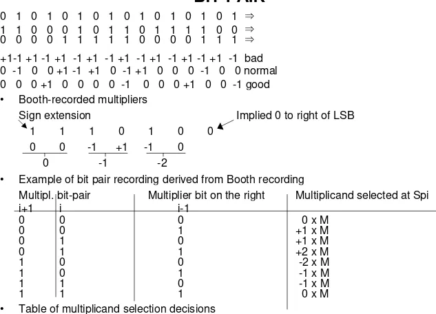
0 1 0 1 0 1 0 1 0 1 0 1 0 1 0 1 ⇒ 1 1 0 0 0 1 0 1 1 0 1 1 1 1 0 0 ⇒ 0 0 0 0 1 1 1 1 1 0 0 0 0 1 1 1 ⇒ +1-1 +1 -1 +1 -1 +1 -1 +1 -1 +1 -1 +1 -1 +1 -1 bad 0 -1 0 0 +1 -1 +1 0 -1 +1 0 0 0 -1 0 0 normal 0 0 0 +1 0 0 0 0 -1 0 0 0 +1 0 0 -1 good • Booth-recorded multipliers
Sign extension Implied 0 to right of LSB
1 1 1 0 1 0 0
0 0 -1 +1 -1 0
0 -1 -2
• Example of bit pair recording derived from Booth recording
Multipl. bit-pair Multiplier bit on the right Multiplicand selected at Spi
i+1 i i-1
0 0 0 0 x M
0 0 1 +1 x M
0 1 0 +1 x M
0 1 1 +2 x M
1 0 0 -2 x M
1 0 1 -1 x M
1 1 0 -1 x M
1 1 1 0 x M
• Table of multiplicand selection decisions
Booth´s Algorithm - a Flowchart
Start
Q(0:n-1) multiplier
Q(n-1) = 0
COUNT =
No
A A + M COUNT COUNT + 1
A 0 Q(0:n) 0 0 M multiplikant No No Yes Yes Yes n - 1?
OUTBUS A
A A M (0:n-1)
COUNT
and Q(n) = 1?
Q(n-1) = 1 Q(n) = 0?
and
OUTBUS Q(0:n-2) A(0) A(0)
M
A
Q
Comments
0.010
0.010
10110
0.010
Subtract M
1.110
1.110
1.111
01011
Shift A,Q
No addition nor subtraction
1.111
10101
Shift A,Q
0.010
Add M
0.001
10101
0.000
11010
Shift A,Q
0.010
Subtract M
1.110
11010
--- Product P
Theoretical Lower Bounds (Fastest Times) For
Addition And Multiplication
R
Denotes each logic element fan-In
N
Denotes number of bits in each operand
T
Represents time (in gate delays)
THEORY
PRACTICE
Addition
T>
LOGR(N-2)
4
LOG
RN
Carry Lookahead
Multiplikation T>
LOG
R2N
2
LOG
3/2(N)
+2
LOG
RN
• Example : R = 4, N = 16
SPEED OF SINGLE CHIP MULTIPLIERS
Speed
Bits
AMD
(Advanced Micro Devices)
40 ns
2x4
25S05
Monolithic Memories Inc.
800 ns
16x16
67516
Motorola
100 ns
32x32
TRW MP4 16
230 ns
32x32
TJ 74S274
70 ns
4x4
MIPS R3010
40 ns