On Verification and Validation of State based Internal Behavioral
Models of Embedded Systems
V. Chandra Prakash, Sastry JKR, D. Bala Krishna Kamesh
K L University, Vaddeswaram, Guntur District 522502
ABSTRACT
Designing and Development of high quality systems require that in process verification and validation of Design models be carried and not leaving the verification and validation till the end of code development. Clean Room
Software Engineering (CRSE) methodology advocates that verification and validation be done in process after completion of designing of different models. CRSE has in it the verification and validation process models after completion of designing of Black Box (BB), State Box (SB) and Clear Box (CB). CRSE advocated formal models
for carrying the verification and validation. While very recently the authors of this paper have published automated formal models for verifying and validating the Black Box structures, no such automated and formal models existed earlier for validation and verifying the state models which are primarily meant for designing the
internal behavior of the embedded systems. In this paper a verification and validation method has been proposed to validate the internal behavior represented by state charts models. The refined CRSE methodology
incorporating the proposed verification and validation method has been presented. The model is used for verifying and validating the State model proposed earlier by the authors for verifying and validating the internal
behavior of a pilot project called “Temperature Monitoring and Controlling of Nuclear Reactor System (TMCNRS)”.
Key words: Embedded Systems, Sate Box, Clean Room Software Engineering, Verification and Validation, UML models
1. INTRODUCTION:
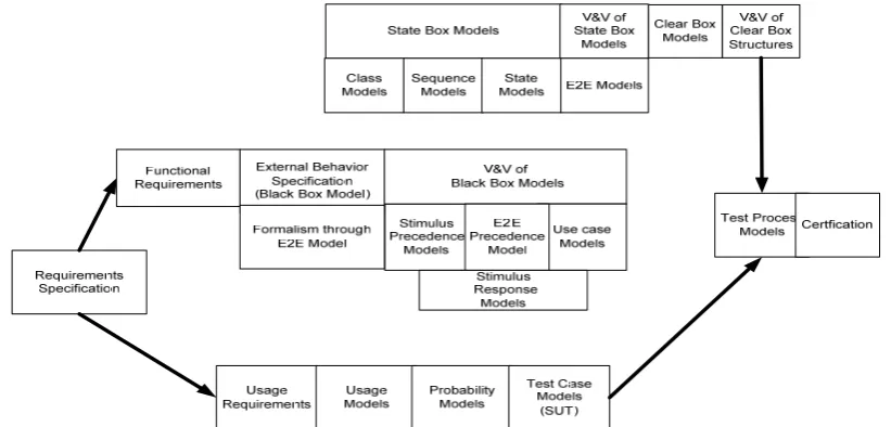
Clean Room Software Engineering methodology is basically aimed at developing high quality systems through implementation of formalism and continuous verification and validation models implemented at every stage of the development. Formal methods which are mathematics oriented have been suggested to present all the phases which are presented covering the development flow of the methodology. CRSE methodology involves two parallel flows; while in one flow the design is undertaken and the other flow deals with undertaking the testing of the code developed through Design Flow. Fig 1.1 shows the CRSE methodology.
Embedded systems must be high quality and fault tolerant, and are built around the internal and external behavior modeling as they are basically stimulus-response models. Many features of CRSE match with the development requirements of the embedded systems. However, some changes are needed in the CRSE methodology so that the methodology can be conveniently used for the development of the embedded systems.
Fig 1.1 Original CRSE Model
The authors further moved on to inventing the formal models, algorithms and the processes for formalizing the development of the internal behavioral models through State Box structures.
.
Fig 1.2 Refined CRSE for formalizing the external and internal behavior model and V&V of external model
The authors now propose a method for verifying and validating state model meant for modeling the internal behavior of the embedded systems.
2.0 RELATED WORK
The evaluation of the quality, on the other hand, is subjective because while the design meets the behavioral requirements, may not necessarily be correct. Therefore, it is necessary that the correctness of the design be assured by testing the design for performance, simplicity, robustness, obviousness, load sharing between components and narrowness of interfaces. A variety of techniques are proposed in Cleanroom Software Engineering methodology to evaluate the correctness through a review process. But here again, no formal mechanism is suggested for evaluating the quality of the design.
Harlan D. Mills [6] advocates discovering state data requirements from the responses which define the necessary information to be maintained in the State Box. By appending the state transitions to the state data, the complete State Box is obtained. This State Box is verified by comparing the intended Black Box with the
derived Black Box obtained by eliminating the state data.
Michael Deck [7] advocated the usage of representative mapping function that defines a correspondence
between elements of the Black Box data space and elements of the State Box data space. The mapping between the State Box data space and the black box data space is usually many-to-one and every point in Black Box must
match at least with one point in the Sate Box.During the definition of the concrete model the State Box designer
should define the representation mapping properly.
State boxes correspond closely to the traditional view of objects as encapsulations of state data and services, or methods, on that data. In this view, stimuli and responses are inputs and outputs, respectively, of specific service invocations.[8]. Box structures bring correctness verification to object architectures. State boxes can be verified with respect to their black boxes, and clear boxes verified with respect to their state boxes. [9]
In all the methods mentioned above, not much formalism has been considered and as such the integration of the methods proposed by them into CRSE methodology has not been advocated.
3.0 PILOT PROJECT – TEMPERATURE MONITORING AND CONTROLLING OF NUCLEAR REACTOR SYSTEM (TMCNRS)
The block diagram at Figure 3.1 shows various hardware components and the integration between them related to TMCNRS.. The mechanical setups that simulate the Nuclear reactors are connected with sensing devices such as Temperature sensors, and actuating devices such as heaters and pumps. Both the sensing and actuating devices are connected to the embedded system (TARGET) and the embedded system is connected to a remote computer (HOST) through which the operator monitors and controls the operation of the nuclear reactor.
The temperature sensors are connected to signal conditioners and the outputs of signal conditioners are
connected to A/D converter which communicates with Micro Controller using I2C Communication protocol.
The output devices which include LCD, interface to HOST, and Relays to actuate pumps are connected to the Micro Controller through its output ports. The access to the embedded system is controlled through a password entered through the key board which in connected to A/D converter. The application running in the embedded system captures the key board strokes and verifies the validity of the password. The rest of the application is invoked when the password is valid.
Different types of outputs are written on LCD such as Help messages, Sensed temperatures, reference temperatures, and temperature mismatches etc. The HOST is connected to the Micro Controller using RS232C interface. The ES application has the interface for reading the reference temperatures and displaying the same on LCD A buzzer is connected to Micro Controller and the buzzer is triggered when the difference in temperatures read is more than a threshold level. The ES board is provided with regulated power supply to drive the Micro Controller and to the relays for activating the pumps. The sensors are mounted on the water tube situated in the mechanical setup. Flow control is achieved through activation and deactivation of the relays that control the Start-Stop mechanism of the pumps. Heaters are used to raise the temperature of the tubes. The mechanical
Figure 3.1 TMCNRS Hardware Integration diagram
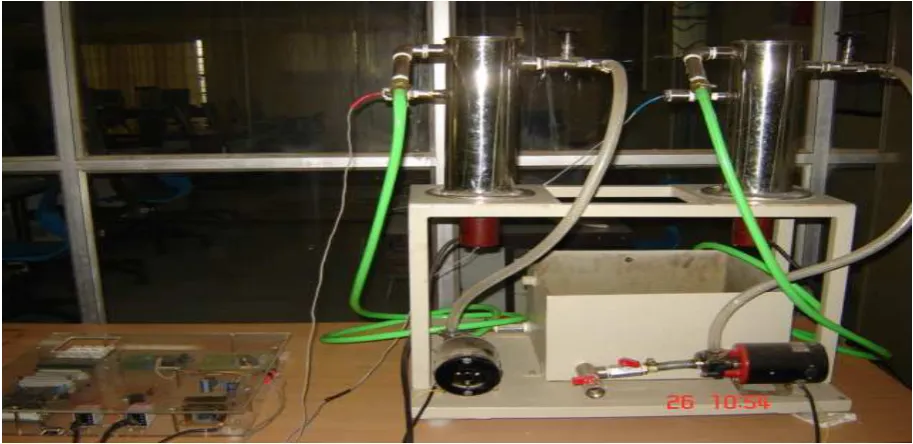
Figure 3.2 Mechanical setup of the TMCNRS
The Embedded application that runs within the Micro Controller has the following tasks:
1. Read Key Board input
2. Validate the Password
3. Read Reference Temperatures from the HOST
4. Write Initialization output to LCD
5. Write actual outputs to LCD
6. Read the sensed Temperatures
7. Compare the Temperatures
8. Actuate the buzzer
9. Set and reset the relays to control the pumps
4.0 DESIGNING FORMAL AND AUTOMATED STATE MODELS
Chandra Prakash, Sastry et al. [5] have proposed models for designing the internal behavior of the embedded
systems and shown the incorporation of the models in the design flow of CRSE methodology. They have proposed the following sequence of operations for arriving at the state models.
1. From the specification of the embedded system, object modeling is done using Class diagrams. The
UML artifact identifies the Objects and the relationships between them.
2. A repository of the objects is created clearly identifying the precedence relationship between them.
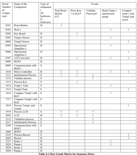
3. All the flow sequences that exist among the objects are generated using the repository of the objects
and a Flow Graph Matrix is created. Each of the columns in the Flow Graph Matrix indicates a sequence flow with the object structure responsible for realizing a use case. A sample Flow Graph
Matrix is shown in the Flow is shown in the Table 4.1
4. Flow sequences are drawn using the Flow Graph Matrix.
5. The State diagram is developed using a separate algorithm which not only presents the top level state
structure but also using the sub charts which completely explain the internal processing of the embedded system.
Each state in the top level State diagram is exploded into further state diagrams based in the composition of elementary level of the states undertaken.
6. A hierarchical State Box structure is developed using the interconnected state diagrams.
The sequence flows shown in the Flow Graph Matrix truly represent the state structure that indicates the internal behavior of the embedded systems. Thus, the Flow Graph Matrix provides the fundamental basis of undertaking the verification and validation of the state models.
5.0 FORMAL FRAMEWORK FOR VERIFICATION AND VALIDATION OF THE STATE MODELS
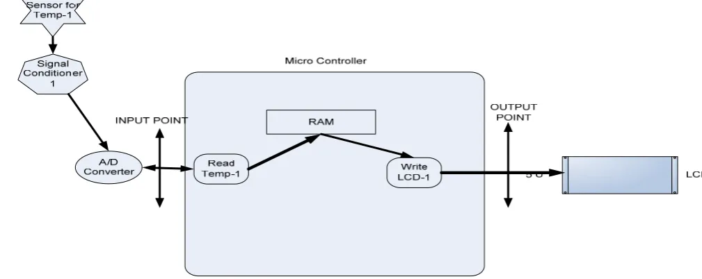
In embedded systems, End-to-End (E2E) processing is important as it refers to the minimal of the processing required. For the TMCNRS system, 19 different process flows have been identified. Each process flow is called as thin thread. The thin threads can be combined to form complex thin threads based on the commonality of processing, thus providing the hierarchical structure to the process flow.
Embedded systems are event driven. The events are either system driven or initiated by an external environment through sensing devices such as Temperature sensors. The sensed data is transmitted and captured by an embedded system. The inputs are processed and the processed results are used to trigger signals that control the physical environment. The entire processing can be represented in terms of a physical thread of execution. An event process is a functional requirement, and the devices involved need that a function be executed as per certain timing considerations and the timing is to be achieved by following a particular pattern.
Event processing within the embedded systems has been a challenge as several issues related to interaction between the Hardware Components, Software Components and in between Hardware and Software Components have to be considered.
E2E processing of an embedded system is more relevant as the entire processing can be recognized in terms of event based processing starting from initiation of an interrupt by the hardware to the processing of emergent requirements and passing the control to mundane tasks which can be executed in a predefined process flow leading to control of physical parameters. This means that the E2E processing can be carried considering the entire system as a whole and not as part of a system. Given a scenario of an embedded system, it is necessary that the processing be completed rather quickly thereby reducing the time required for processing the event.
Raymond Paul [9] presented the concept of thin threads which are true representatives of the functional
Unlike the loaded systems, the embedded systems are event driven and the events either occur randomly or in a cooperated sequence. The occurrence of some of the events is conditional. The occurrence of the events can
also happen in terms of some patterns. Feng Zhu et al. [10] have presented event patterns which together form
the basis for processing occurrence of a set of events in a sequence.
About 80% of time is to be spent on integrated processing of the embedded systems as the integration of Hardware devices, integration of Software components and the integration of software components with the Hardware devices is the major effort to complete the entire processing. The integrated processing of the embedded system must be conducted considering the entire system as a whole.
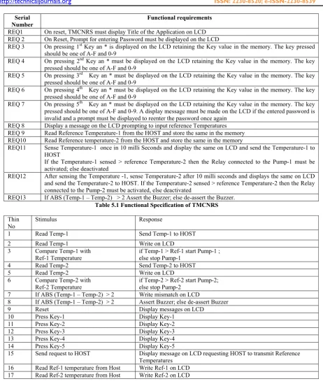
The functional requirements traced from the description of the embedded system shall be the basis of identifying the thin threads. Table 5.1 shows the functional requirements of the TMCNRS. From the functional requirements one can trace stimulus –responses and each stimulus-response shall represent a thin thread in the
system. The list of stimulus-response sequences for the TMCNRS is presented in Table 5.2. Fig 5.1 to 5.5
shows some samples of E2E flows of the TMCNRS.
Fig 5.1 Thin Thread for reading the Temperature-1 and writing to LCD
Fig 5.3 Thin Thread for comparing Temperature -1 and Temperature -2 and actuating the buzzer in case of mismatch
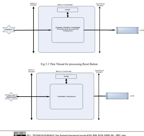
Fig 5.3 Thin Thread for processing Reset Button
Fig 5.3 Thin Thread for password validation
All the thin threads have process components and the process components exist in a sequence. A repository of relationships between the process components can be captured and maintained. The table showing the
relationships is shown in Table 5.3. Using the threads mentioned above, a Flow Graph Matrix is formed by
using the following Algorithm. For each of the thin threads, add a column to the Flow Graph Matrix and map the process components to the respective rows by following the logic below:
{
For each of the Process components, identify its preceding components by referring to the Table 5.3
{
If any of the preceding components exists in any of the existing row, then create a row after the last preceding component and map the component to the row-column
If the current component is preceding component to the existing component, then create a row before the existing component and map the component to row-column
}
For each of the row pair related to two process components, check the precedence using the Table 5.3.
If the precedence fails, then interchange the rows
}
The Flow Graph Matrix thus prepared by executing the above mentioned algorithm is shown in the Table 5.4. One can easily verify that the Flow Graph Matrix generated to develop the state model and the Flow Graph Matrix generated through E2E are same and therefore the state model has been built correctly representing the internal behavior of the system.
6.0 Conclusions
CRSE methodology has been recommended keeping in view of the formalism for presentation of accurate specification, hierarchical structure for handling complexity, and gradual development through incremental and iterative models. CRSE however have not recommended formal models for undertaking different phases of development as recommended in the methodology. CRSE has not only recommended the formal models for the design of internal behavioral models but also the formal models required for verification and validation of the behavioral model. No formal models are in existence in the literature as today to conduct verification and validation using the formal models.
UML has provided excellent platform to deliver different types of formal models. In this paper an approach is recommended using UML artifacts for formalizing the verification and validation of internal behavior of embedded systems through generation of sequence flows using class models and E2E processing models. The verification and validation is presented through development of data repositories from two sources which include classes and E2E processing and proving that the repositories are the same.
The models presented in this paper or formal and can be used to automate verification and validation of internal behavior models represented as state charts. This paper has provided a verification framework for verifying and validating the State models developed to exhibit the internal behavior of the embedded systems.
References
[2] Dr Sastry JKR, Prof. V Chandra Prakash et al., “A formal framework for presenting requirement specifications of an embedded systems as a Black Box structure”, Proceedings of International Joint Conference on Information and Communication Technology (IJCICT-2010) January, 2010
[3] Dr Sastry JKR, Prof. V Chandra Prakash et al., “A Formal Framework for Modeling External Behavior of an embedded system as a Black Box structure”, Proceedings of IEEE sponsored 4th International Conference on "Embedded and Multimedia Computing", EM-Com 2009 Dec. 2009.
[4] Dr Sastry JKR, Prof. V. Chandra Prakash et al., “A formal Framework for Verification and Validation of External Behavior models of embedded systems through Use Case Models”, IEEE sponsored 4th International Conference on "Embedded and Multimedia Computing", EM-Com 2009 Dec. 2009.
[5] Prof. V. Chandra Prakash, Dr. Sastry JKR, et al. “Internal Behavioral Modeling of Embedded Systems through State Box Structures”, Paper communicated to “International Journal on Advanced Networks and Applications” for publication.
[6] Harlan D. Mills, “Stepwise Refinement and Verification in Box-Structured Systems”, Journal IEEE Computer, Jun-88, Volume 21 Issue 6, Page 23-36
[7] Michael Deck, “Data Abstraction in the Box structures Approach”, 3rd International conference on
Cleanroom Software Engineering practices, Oct 10-11, 1996, college park, MD
[8] Linger, R.C., “Clean room Software Engineering for Zero- Defect Software”, Proceedings of 15th International Conference on Software Engineering, 1993.
[9] Mills, 13. D., R. C. Linger, and A. R. Hevner, “Principles of Information Systems Analysis and Design”, Academic Press, San Diego, CA, 1986.
[10] Paul Raymond, “End-to-End Integration Testing ”, Ph.D. thesis, Dept. of Computer Science and Engineering, University of Minnesota, Minneapolis, MN, 2001
2011 - TECHNICALJOURNALS®, Peer Reviewed International Journals-IJCEA, IJESR, RJCSE, PAPER, ERL - PBPC, India; Indexing in Process - Scopus, EMBASE, COMPENDEX, EmCARE, Electronics & Communication Abstracts, SCIRUS, SPARC, GOOGLE Database, EBSCO, NewJour, Worldcat,
Serial
0909 Communication with
HOST
1616 Compare Temp1 with
Ref1
S √
1717 Compare Temp2 with
Ref2
S
1818 Process Temp1 and
Temp2
S √
1919 Process LCD S √ √ √
2020 LCD H √ √ √
2112 Validation process S √
2211 Initialization Process S √
2309 Communication with
HOST
2011 - TECHNICALJOURNALS®, Peer Reviewed International Journals-IJCEA, IJESR, RJCSE, PAPER, ERL - PBPC, India; Indexing in Process - Scopus, EMBASE, COMPENDEX, EmCARE, Electronics & Communication Abstracts, SCIRUS, SPARC, GOOGLE Database, EBSCO, NewJour, Worldcat,
Serial Number
Functional requirements
REQ1 On reset, TMCNRS must display Title of the Application on LCD
REQ 2 On Reset, Prompt for entering Password must be displayed on the LCD
REQ 3 On pressing 1st Key an * is displayed on the LCD retaining the Key value in the memory. The key pressed
should be one of A-F and 0-9
REQ 4 On pressing 2nd Key an * must be displayed on the LCD retaining the Key value in the memory. The key
pressed should be one of A-F and 0-9
REQ 5 On pressing 3rd Key an * must be displayed on the LCD retaining the Key value in the memory. The key
pressed should be one of A-F and 0-9
REQ 6 On pressing 4th Key an * must be displayed on the LCD retaining the Key value in the memory. The key
pressed should be one of A-F and 0-9
REQ 7 On pressing 5th Key an * must be displayed on the LCD retaining the Key value in the memory. The key
pressed should be one of A-F and 0-9. A display message must be made on the LCD if the entered password is invalid and a prompt must be displayed to reenter the password once again
REQ 8 Display a message on the LCD prompting to input reference Temperatures
REQ 9 Read Reference Temperature-1 from the HOST and store the same in the memory
REQ10 Read Reference temperature-2 from the HOST and store the same in the memory
REQ11 Sense Temperature-1 once in 10 milli Seconds and display the same on LCD and send the Temperature-1 to
HOST
If the Temperature-1 sensed > reference Temperature-2 then the Relay connected to the Pump-1 must be activated; else deactivated
REQ12 After sensing the Temperature -1, sense Temperature-2 after 10 milli seconds and displays the same on LCD
and send the Temperature-2 to HOST. If the Temperature-2 sensed > reference Temperature-2 then the Relay connected to the Pump-2 must be activated, else deactivated
REQ13 If ABS (Temp-1 – Temp-2) > 2 Assert the Buzzer; else de-assert the Buzzer.
Table 5.1 Functional Specification of TMCNRS
Thin
if Temp-2 > Ref-2 start Pump-2; else stop Pump-2
15 Send request to HOST Display message on LCD requesting HOST to transmit Reference
Temperatures
16 Read Ref-1 temperature from Host Write Ref-1 on LCD
17 Read Ref-2 temperature from Host Write Ref-2 on LCD
2011 - TECHNICALJOURNALS®, Peer Reviewed International Journals-IJCEA, IJESR, RJCSE, PAPER, ERL - PBPC, India; Indexing in Process - Scopus, EMBASE, COMPENDEX, EmCARE, Electronics & Communication Abstracts, SCIRUS, SPARC, GOOGLE Database, EBSCO, NewJour, Worldcat,
Serial Number of Component
Name of the Process Component
16 Process Key S Initialization Process
17 Validate Password S Initialization Process
18 Process LCD S Initialization Process
Validate Password Temp 1 Task Temp 2 Task
Communicate with HOST Process Temp-1 and Temp2 Task
19 Initialization Process S Micro Controller
20 Communication with
HOST
S Initialization Process
Temp1-Task Temp2-Task HOST
21 Temp-1 Task S Micro Controller
A/D Converter
22 Temp2-Task S Micro Controller
A/D Converter
23 Compare Temp1 with
Ref1
S Temp1 Task
24 Compare Temp2 with
Ref2
S Temp2 Task
2011 - TECHNICALJOURNALS®, Peer Reviewed International Journals-IJCEA, IJESR, RJCSE, PAPER, ERL - PBPC, India; Indexing in Process - Scopus, EMBASE, COMPENDEX, EmCARE, Electronics & Communication Abstracts, SCIRUS, SPARC, GOOGLE Database, EBSCO, NewJour, Worldcat,
Temp2
Micro Controller
26 Process Buzzer S Process Temp1 and Temp2
Table 5.3 Relationships between the process components of the thin threads
Serial
0505 Operational Amplifier-1 H √
0606 Operational Amplifier-2 H √
0707 A/D Converter H √ √ √
0808 HOST H
0909 Communication with
HOST
2211 Initialization Process S √
2309 Communication with
HOST