LABORATORY MANUAL OF
EXPERIMENTAL ORGANIC CHEMISTRY I
Compiled By:
Jamaludin Al Anshori, M.Sc.
Laboratory of Organic Chemistry
Faculty of Mathematics and Natural Sciences
Universitas Padjadjaran
LABORATORY MANUAL OF
EXPERIMENTAL ORGANIC CHEMISTRY I
Compiled by:
Jamaludin Al Anshori, M.Sc.
LABORATORY OF ORGANIC CHEMISTRY
FACULTY OF MATHEMATICS AND NATURAL SCIENCES
UNIVERSITAS PADJADJARAN
JATINANGOR
JATINANGOR, AUGUST 21, 2008
Approved by:
Compiler:
Head of Organic Chemistry Laboratory
i
TABLE OF CONTENTS
Table of Contents ... i
Preface ... iv
A.Laboratory’s Rules……… v
B.Introduction to The Laboratory………vii
Laboratory Techniques : Experiment 1 I.1 Extraction...1
I.1.1 Introduction... 1
I.1.2 Using the separating funnel ... 2
I.1.3 Procedure ... 3
I.1.4 Question ... 3
Experiment 2 II.1 Recrystallization ...4
II.1.1 Introduction... 4
II.1.2 Procedure ... 4
II.2 Melting Point ...4
II.2.1 Introduction... 4
II.2.2 Apparatus for Melting-Point Determination ... 5
II.2.3 Procedure ... 7
Experiment 3 III.1 Chromatography ...8
III.1.1 Introduction ... 8
III.1.2 Laboratory Practice... 9
III.1.2.1 Thin-Layer Chromatography ... 9
III.1.2.2 Column Chromatography... 10
III.1.2.3 Pencil Columns... 10
III.1.3 Procedure ... 11
III.1.3.1 Separation of Ink Pigments by Thin-Layer Chromatography ... 11
III.1.3.2 Separation of Plant Pigments by Thin-Layer Chromatography ... 12
ii
III.1.4 Questions ... 12
Experiment 4 IV.1 Distillation ...13
IV.1.1 Introduction... 13
IV.1.2 Fractional Distillation ... 14
IV.1.3 Vacuum Distillation... 15
IV.1.4 Steam Distillation... 15
IV.1.5 Laboratory Practice ... 17
IV.1.5.1 Simple Distillation ... 17
IV.1.5.2 Fractional Distillation ... 17
IV.1.6 Questions ... 19
IV.2 Refractive Index ...19
IV.2.1 Introduction... 19
IV.2.2 Procedure... 21
Experiment 5 V.1 Functional Group Identification...22
V.1.1 Introduction... 22
V.1.2 Alcohols... 24
V.1.2.1 Ritter Test... 24
V.1.2.2 Lucas Test... 24
V.1.2.3 Iodoform Test ... 25
V.1.3 Aldehydes and Ketones ... 25
V.1.3.1 2,4-Dinitrophenylhydrazone Test... 26
V.1.3.2 Tollens' Reagent (Silver Mirror Test)... 26
V.1.3.3 Schiff's Fuchsin Test ... 27
V.1.4 Nonaromatic Hydrocarbons... 27
V.1.4.1 Permanganate Test (Baeyer Test) ... 28
V.1.4.2 Bromine Test ... 28
V.1.5 Aromatic Hydrocarbons... 28
V.1.5.1 Friedel-Crafts Test... 29
V.1.6 Phenols ... 29
V.1.6.1 Ferric Complex ... 29
V.1.7 Alkyl and Aryl Halides... 30
iii
iv
Preface
Organic chemistry, from its very beginning, has used specific tools and technique for the synthesis, isolation, purification of compounds, and physical method for determination of their properties. Much of the success of the organic chemist depends upon a wise selection and a skillful application these methods.
Technique, and tools, which, with the progress of the science, have become numerous and often intricate In developing material for a laboratory course in organic chemistry, a number of choices must be made, and a course be steered between several conflicting factors. Students very greatly in ability, Schedules are tight for both student time and laboratory space and facility. But the course must not be restricted to a collection of simple cut and dried procedure.
The increasing sophistication of experimental organic chemistry requires more elaborate experiment to provide meaningful and useful experience. This laboratory manual is designed for one semester course in organic chemistry with two four-hour laboratory period per week. The manual is designed to suit the need undergraduate student of chemistry. The authors give the simple theoretical background for understanding of the operation and a more rational application of the respective procedure. The field is broad and some of it is difficult to survey. However, the present laboratory manual didn't cover a comprehensive presentation of technique which used in organic laboratory and which are available for the investigation of organic compounds. Author hope that the manual will be found useful and that many of the readers will let them have benefit or their criticism and of suggestion for improvements.
Compiler,
v
A. LABORATORY'S RULES
1. Practicians must wear laboratory uniform in every laboratory activities including during the discussion time.
2. Practicians must prepare the journal, report, and other tasks before practice begin. 3. Practicians not allowed eating, drinking and smoking in laboratory.
4. Practicians not allowed entering assistant room, storage and the research laboratory without permission from the assistant.
5. Except journal and laboratory kit, other should not be placed on the practice table.
6. Practice is done in definite workday and practicians not allowed working outside these days without pennission from the assistant.
7. Practicians should pay attention to sign (bell sound) at the beginning and at the end of practice time.
8. The fill up of attendance list will be done every workday including in every laboratory activities. 9. Practicians not allowed to left the laboratory during the work hour without pennission from the
assistant. Leaving more than 15' should be with written permission. 10. During the experiment activities, all windows should be opened.
11. Practicians that have finished the practice should asked for the signature of assistant. 12. Practicians not allowed to take chemistry compound from storage, the assistant will prepare
the chemistry compounds. Every chemistry compound bottle should be clean and dry. 13. Liquid reagents test must be applied by pipette
14. Solid reagents test must be applied by spatula.
15. Reagents should be placed on reagents table and not allowed to remove. 16. Every tool should be used according to its utility.
17. Laboratory kit contains boiling chips, pipette, spatula, vial, matches, and stirring stick. 18. Cleanness kit contains napkin, tube brush and detergent.
19. Each tool must be clean and dry before the storage.
20. Practicians not allowed keeping chemical compounds in the drawer except with the pemlission from assistant.
21. Before leaving the laboratory, fume hood, weight room, laboratory, floor, washing stand, table and seat should be clean and neat. Water, gas, electricity and windows should be shut down. 22. Journal contents are experiment's number, procedure, chemical and physical properties of
vi
23. Report and tasks must be wrote on A4 paper and covered. Cover contents are practician code, experiment's number, name, NPM, date of experiment, name of the assistant.
24. Each journal must. have agreement from assistant otherwise practician not allowed to do the experiment.
25. Journal, report and tasks should be handed over before the experiment begins. Practician who don't hand over the journal, report and tasks on time won't be allowed to do the experiment.
26. Report and tasks that have been handed over can't be taking back by practicians.
27. In everything related with Organic Chemistry Laboratory practicians are not allowed to cheat. Any violation related to this rule, will caused restitution of practician back to his/her own department and will not allowed to practice for 1 or 2 semester, or the case will be handle by university.
28. Repeated warning that caused by repeated violation will affected to practice point. 29. Practician must obey the rules without any exception.
NOTES
1. Practicians can have final exam after completed all experiment, report, and tasks, collect all journals and finished all problems of tools and tables.
2. Each tool that returns to laboratory should be in good and clean condition. 3. Tables should be returned in clean and neat condition. And so as the laboratory.
vii
B. INTRODUCTION TO THE LABORATORY
B.1 Laboratory Safety B.1.1 Safety Equipment
A set of safety rules is written on the inside behind cover of this book. Careful observation
of these rules will help to prevent accidents in the laboratory. However, from time to time accidents can occur. Therefore, safety equipment is installed for his eventuality in the laboratory. Safety equipment should include:
9 An eye wash
9 A safety shower
9 Fire extinguishers
9 Hoods
9 First-aid kit.
B.1.1.1 Eye Wash
The eyewash is designed to flush irritating chemicals from the eyes. It should be capable of providing a stream of water for at least 15 minutes. In the event of an eye accident, you should proceed to the eyewash at once and wash the eye for at least 15 minutes. During this process, the eye should be kept open. The eyes are the most vulnerable part of the body. In the event of any eye injury notify the instructor at once. All eye injuries should be immediately examined by a health professional.
Never use the eyewash for anything other than its intended purpose.
B.1.1.2 Safety Shower
The safety shower is designed for two purposes, namely, to extinguish clothing fires and to provide a whole bodies wash if a large chemical spill occurs.
i. Clothing Fires: If your clothing catches fire, perhaps the best rule is to fall and roll. Never run to a shower with your clothes on fire, it will only fan the flames. Use the shower afterwards to squelch any residual embers.
viii
B.1.1.3 Fire Extinguishers
In the laboratory, you will sometimes work with flammable materials. For most purposes, ABC fire extinguishers are adequate to extinguish most fires. Several of these extinguishers should be placed in the laboratory. Learn their location. Your instructor will demonstrate their use before you begin to work in the laboratory .
ABC-type extinguishers (e.g., lithium aluminum hydride or sodium) cannot extinguish some materials. In these circumstances, appropriate extinguishing materials will be provided and their use demonstrated before the experiment begins.
B.1.1.4 Hoods
If possible, do all experiments in a hood. The ventilation system draws the fumes generated by an experiment away from the experimenter. The walls of the hood enclose the experiment on five sides. Therefore, if on explosion or spill occurs, the experiment can be contained. A sliding transparent sash augments all these features. The sash should always be kept between the individual's eyes and the experiment. In a modern organic laboratory, chemica! reactions are always done in a hood.
B.1.1.5 First Aid Kits
First aid kits are used for minor injuries. Report all cuts and bums to the instructor, and at his/her discretion, visit the school physician for further treatment.
i. Cuts: All cuts should be cleaned carefully to remove any chemical residue or broken glass before a Band-Aid is applied.
ii. Bums: Immediately flush bums under cold water for 15 to 20 minutes to reduce the magnitude of the injury. Do not rub the affected area or pack it in ice. If a seemingly minor injury appears to be getting worse, consult a physician.
B.1.2 Personal Protective Equipment
Wearing the proper clothing during an experiment is as important to an individual's safety as any other safety feature of the laboratory. This protective clothing should include the following.
B.1.2.1 Safety Glasses
ix
Some individuals wear contact lenses rather than corrective glasses. This practice is not recommended in the laboratory. Soft contact lenses actually accumulate organic vapors and hold them against the eye. Serious injury can result. Hard (J.e.,glass) contact lenses are somewhat better, however, in the event of a splash, the material can be drawn under the lens by capillary action. If during an experiment any irritation of the eye occurs, remove the contact lenses, wash the eye at the eyewash, notify the instructor, and leave the laboratory. A physician should be consulted as soon as possible. Ordinary glasses are not safety glasses. In the event of a splash, they do not provide lateral protection. In additions, street glasses are frequently made of plastic, and they can be ruined easily by the solvents in the laboratory.
B.1.2.2 Lab Coats
Lab coats are designed to removed quickly in case of a fire or chemical spill. Lab coats provide protection against the minor spills and splashes of the laboratory. The coat should at least protect the upper body from the neck to the waist, and preferably, it should protect it to the knees. The lab coat should be made of cotton, not synthetic materials. During a clothing fire, a synthetic material melts and becomes incorporated into the burn. Synthetic lab coats tend to dissolve in organic solvents, therefore, they are not as durable as cotton ones.
B.1.2.3 Shoes
Proper laboratory footwear completely covers the foot. It may be either a street shoe or a sneaker, but sandals or open-toed shoes should not be worn. It is advisable to have a pair of sneakers in your locker and to change into them before the lab period begins.
B.1.2.4 Gloves
If toxic or colored (dyes) substances are used in the laboratory, the instructor may advise wearing gloves. Disposable gloves are preferred, and they should be worn only for as long as necessary.
B.1.3 Good Laboratory Practice
1.Food or Drink in the Laboratory: Food and drink should not be brought into the laboratory. Packaged materials (including lunches) can absorb materials from the air. Food consumed in the laboratory can easily become contaminated.
2. Also, beverages can easily absorb toxic vapors from the air. Serious cases of poisoning have resulted from this type of occurrence.
x
i. As with food consumption, material from the air, hands, and desk can be carried to the mouth during smoking.
ii. Cigarettes represent an unacceptable ignition hazard in the laboratory Cleanliness: During a laboratory experiment, you are exposed to a wide variety of chemicals. They can be retained on the hands, especially under the fingernails. It is a good laboratory practice to make sure your hands are clean before you leave the laboratory .
B.1.4 Safe Handling of Laboratory Equipment
Heat Sources: Gas burners, heating mantles, and steam baths are used as heat sources in the laboratory. Each source has its appropriate use and precautions.
B.1.4.1 Gas Burners (i.e., Bunsen Burners)
These devices provide instant high temperature (up to 1100 °C). However, the open flame represents a serious ignition hazard. For This reason, gas burners should no be used near volatile and easily ignited materials Furthermore, glass should not be heated directly in an open flame because the concentrated heat may cause it to crack.
B.1.4.2 Bunsen Burners
Bunsen burners are used infrequently in student labs. However, when they are used, a ceramic heating pad should be placed between the flame and the flask. Never leave a lit burner unattended.
B.1.4.3 Heating Mantles
These devices heat more slowly than a gas burner, and thus reach a lower temperature. Heating mantles use electricity as a source of heat, therefore, they should be kept dry, when used they should be connected to power only through a ground fault interrupter.
B.1.4.4 Steam baths
Steam baths provide a convenient source of heat for temperatures ranging from room temperature to 95°C. Steam, however, has a high heat of vaporization, and live steam can cause severe scalding.
B.1.5 Electrical Equipment
xi
B.1.5.1 Ignition Hazard
Electrical motors spark frequently during operation. These sparks can cause fires or explosions. For this reason In areas where solvents are located, only spark-free motors should be used. The problem of sparking also exists with switches and plug connections. These devices should be on the outside of the hood where the concentration of solvent vapor is low and where the danger of igniting it is minimal.
B.1.5.2 Shock Hazard
Do not use poorly maintained equipment (e.g., frayed cords, loose plugs, etc.). Keep these devices dry and away from the puddles of water that may collect in a hood. All these devices should be connected through ground-fault interrupters to minimize shock hazards.
B.1.6 Waste Disposal
Every laboratory experiment generates by products (e.g., spent solvents, pot residues, etc.) that must be disposed of. The proper disposal of laboratory wastes is as much a part of the experiment as the synthesis and isolation of the product. Some general rules follow for disposing of chemical wastes.
B.1.6.1 Chemical Spills
Chemical spills should be cleaned up as soon as they occur. The residues from the clean up should be placed in a properly labeled container for later disposal. Do not attempt to clean up a large spill (i.e., 100 ml or more).
B.1.6.1.1 Solids
Sweep up solids and dispose of them in an appropriately labeled container.
B.1.6.1.2 Liquids
xii
B.1.6.1.3 Mercury
Broken thermometers are a common source of spilled mercury in the laboratory. Clean up such spills immediately. Amalgamating agents are commercially available to remove such spills completely. Place the spent clean-up material and any free mercury in a separate waste container reserved for the disposal of mercury wastes. Dusting the spill with elemental sulfur is not an adequate clean-up procedure.
B.1.6.1.4 Broken Glass
Broken laboratory equipment often produces fragments wit razor-sharp edges and needlepoint. Place this broken glassware in a specially labeled container not in the c;ommon trash. WARNING: Do not combine residues from chemical spills unless specifically told by the instructor. Violent chemical reactions can result from these mixtures.
1. Chemical Reaction Wastes: Chemical reaction wastes are usually of known composition, and disposal can be planned ahead of time. Instructions for such disposal are found in the note column of each experiment. It is imperative that wastes be placed in the correct container. These containers should be used for only one experiment. The mixing of waste stream from various experiments should be used for only one experiment. Only the instructor should do the mixing of the waste streams from various experiments. Violent chemical reactions can result from the careless mixing of such waste streams.
2. Spent Acids and Bases: Carefully neutralizes these materials and pour them down the drain. This procedure should be followed only if the resulting salt is non hazardous. Otherwise, the spent material should be placed in a container for disposal. Solids
a. Nonhazardous: If the materials are water soluble, dissolve them in water and flush them down the drain. Insoluble materials should be labeled and disposed of as nonhazardous solid waste.
b. Hazardous: Place these materials in a properly labeled container and save them for hazardous waste disposal.
1
E X P E R I M E N T 1
I.1 E
X T R A C T I O N
I.1.1 Introduction
There are two main application of extraction on organic laboratory: (1) the separation and
isolation of substances from mixtures of solids, typically those that occur in nature and (2) the
selective isolation of substances from solutions of mixtures that arise in synthetic chemistry.
Extraction of Solids. Examples of extractions of solid mixtures are the extraction of alkaloids from leaves and bark, flavoring extracts from seeds, perfume essence from flowers, and
sugar from sugar cane. Solvents commonly used for this purpose are ether, dichloromethane,
chloroform, acetone, various alcohols, and water. In the laboratory, a common form of apparatus
for continuous extraction of solids by means of volatile solvents is the Soxhlet extractor (Figure
1.1), meanwhile discontinuous one is Maceration extractor.
Extraction of Solutions. A more common application of extraction is in “liquid-liquid” extraction, which is used to isolate a substance dissolved in one solvent by shaking the solution
another solvent, immiscible with the first, in a separatory funnel and continuous extractors (Figure
1.1).
Figure 1.1 Soxhlet Extractor and Continuous Extractor Assembly
In this course, the term "extraction" refers to the process whereby a component in a
mixture is transferred into another solvent phase: The operation involves shaking an immiscible
pair of liquids, whereby a solute passes from one liquid to the other. Commonly, one of the liquids
2
will be an aqueous (water) solution and the other, an organic solvent (e.g.diethyl ether or CH2CI2)
or a solution involving an organic solvent).
Before using the separating funnel, apply a thin coat of grease or, when dichloromethane
is used as solvent, a film of water, to the glass tap (DO NOT grease Teflon taps). Check for leaks
by adding a small volume of the solvent to be used to the separating funnel with the tap inserted
and closed.
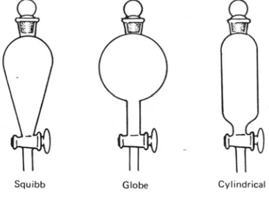
I.1.2 Using the separating funnel (Figure 1.2):
1. Close the tap.
2. With the separating funnel supported in a ring clamp, add the two liquid phases and insert
the stopper.
3. Remove funnel from ring clamp and, holding the stopper firmly with the palm of one hand,
invert the funnel and release pressure through the tap.
4. After closing the tap, shake the funnel several times whilst holding both the stopper and
the tap.
5. At frequent intervals during an extraction, release excess pressure through the tap. Take
care not to point the stem, at your neighbor during this operation.
6. When the extraction is completed, replace the separating funnel in the ring clamp, remove
the stopper and allow the phases to settle.
7. Drain the lower phase into an appropriate container, and then pour out the upper phase
through the neck of the funnel into another container.
Figure 1.2 Extraction Funnel
Extraction is based on the differential solubility of compounds in various solvents. The
solvents (used in pairs) for extraction must be immiscible. Water is frequently used as one of the
pair because its solvent ability can be dramatically altered by changing its pH during the course of
3
an extraction sequence. It has the further advantage of being insoluble (immiscible) in most organic
solvents.
In a typical extraction, a mixture of two compounds is dissolved one solvent placed in a
separator funnel. and then shaken (extracted) with a second, immiscible solvent. Ideally, one of the
compounds in the mixture will be preferentially extracted into the new solvent leaving the other
compound behind in the original solvent. The new solvent can then be separated from its
immiscible partner. Solvent removal from the two layers will yield two separate compounds in a
reasonably pure state.
I.1.3 Procedure
In a 500 mL Erlenmeyer flask place 30 g of ordinary dry tea, 300 mL of water and 15 g of
powdered calcium carbonate. After boiling the mixture gently with occasional swirling for 20
minutes, add 5 g of Celite or other filter aid, filter the hot mixture on a Buchner funnel and press the
filter cake firmly with a large cork to obtain as much as possible of the liquid. Cool the aqueous
extract to 15-20°C, transfer it to a separatory funnel and extract the caffeine with three successive
25 mL portions of methylene chloride (Chloroform).
Pour the combine chloroform extract into an Erlenmeyer flask and add 0,5 g sodium sulphate.
Decant the chloroform solution from sodium sulfate indicant flask. Evaporate the solvent on the
steam bath. Scrape the dry product from the flask and weight the crude caffeine.
I.1.4 Question
1. Define Polarity!!!
2. What are some of advantages and disadvantages of ether as an extraction solvent?
3. Why is it inadvisable to filter a hot solution of chloroform by suction filtration?
4. Boiling chips should never be added to a liquid that is near its boiling point. Why?
5. The distribution coefficient for a certain organic compound between ether and water is 1.
Show the amount of the compound extracted from 25 mL of water containing 1 g of the
compound by one 75 mL portion of ether and the amount extracted by three 15 mL
portions of ether?
4
E X P E R I M E N T 2
II.1 R
E C R Y S T A L L I Z A T I O N
II.1.1 Introduction
Recrystallization of a crystalline material is carried out in order to remove impurities.
Briefly, the procedure involves dissolving the material in an amount of solvent that will produce a
saturated solution at a temperature close to the boiling point of the solvent. Insoluble impurities are
removed by gravity filtration of the hot solution and the purified compound crystallizes as the filtrate
cools. Suction filtration is used to isolate the purified crystals.
The steps involved in recrystallization may be defined as follows:
1. Select the solvent.
2. Dissolve the material in the hot solvent.
3. FiIter the solution if necessary.
4. Allow crystallization to take place.
5. Collect the crystals.
6. Wash the crystals.
7. Dry the crystals.
II.1.2 Procedure
Dissolved the crude of caffeine (experiment 1) in a minimum amount of acetone by
warming the mixture on steam bath. Add drop wise just enough mixed "hexane" to turn the warmed
solution faintly cloudy,then allow the solution to cool and allow the product to crystallize. Collect the
green-tinged crystals on a small vacuum filter and wash them with a little mixed 'hexane".
II.2 M
E L T I N G
P
O I N T S
II.2.1 Introduction
The Theory of Melting-Point Depression. The molecules of a crystal are aligned in regular
patterns. As the temperature of the crystal is raised, the increasing vibrational motions of the
molecules makes it more difficult for the regularity to be preserved. Eventually a temperature is
reached (the melting temperature or melting point) at which the pattern is broken and the solid
melts and turns into a disordered liquid. A pure crystalline substance usually possesses a sharp
5
melting point; i.e., it melts completely over a very small temperature range (in practice, not more
than 0.5-1.0°). The presence of even small amounts of impurities soluble in the molten compound
will usually produce a marked depression of the temperature at which melting begins as well as a
smaller depression at which the last crystal disappears, resulting in a large increase in the
melting-point range. The amount of lowering of the final temperature at which the last crystall disappears is
called the melting-point depression.
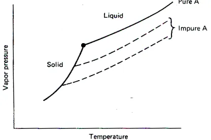
The situation is entirely different in the solid phase. Here the original substance and the
impurities usually form a heterogeneous mixture of crystals of each substance. The crystals are so
intimately mixed that it is impractical to try to separate them, yet at a molecular level, they behave
as though they were independent of each other. As a consequence, the vapor pressure of the solid
substance is essentially unaltered by the presence of impurities, which may be thousands of
angstroms (Å) away. This behavior is shown in Figure 2.1 as a vapor pressure curve for the solid
that is independent of the presence of impurities. Since by definition the temperature at which
melting ends is the the temperature at which the solid and melt have the same vapor pressure (the
point of intersection of the solid and liquid curves), that temperature will be depressed by the
presence of an impurity. The greater the amount of impurity (at least up to a point, to be described
later), the larger is the melting-point depression.
Figure 2.1 Vapor Pressure Of Subtance A in Solid and Liquid Phases
II.2.2 Apparatus for Melting-Point Determination
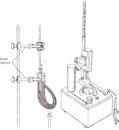
One common method for determining melting points is to use the Thiele apparatus
illustrated in Figure 2.2. The sample is contained in a capillary tube. The thermometer is inserted
into a drilled cork or rubber stopper and supported by means of a buret clamp. The thermometer
position is adjusted so that it is centered vertically in the Thiele tube. with the upper end of the
6
mercury bulb about 1 cm below the side arm. The capillary tubes usually come with one end
sealed. If yours do not, a tube can be sealed by touching one end to a small, hot flame.
A small amount of the material to be examined (0.05 g is sample) is pulverized finely by
crushing it with a spatula or knife blade on a piece of smooth, hard paper or a watch glass. The
crushed material is collected into a small mound, and the open end of the capillary tube is thrust
into it. The tube is then inverted, and the solid is shaken down into the tube by tapping the lower
end on the desk top; alternatively, the solid may be forced down by dropping the tube (sealed end
downward) through a 2-ft length of ordinary glass tubing onto the desk top. Further increments of
the sample are introduced in the same way, until the material forms a compact column 3-5 mm high
at the bottom of the tube after repeated tapping. It is essential that the material be pulverized finely
and packed tightly to ensure rapid transfer of heat throughout the sample.
Although the capillary tube will usually adhere to the thermometer by capillary action of a
thin film of bath liquid, it should be attached more firmly by means of a thin slice of rubber tubing or
a small rubber band. The tube should be adjusted so that the sample is just alongside the mercury
bulb of the thermometer, and the rubber fastening should be above the level of the bath liquid (to
avoid softening of the rubber and discoloration of the bath).
The Thiele tube is heated at its lowest point. The resulting convection currents will
circulate the oil in a counterclockwise direction if the apparatus is set up as shown in Figure 2.2.
The tube may be heated at a fairly rapid rate until the bath temperature approaches within 15-20°
of the melting point (roughly determined in a preliminary trial, if necessary). Heating is then
continued with a very small flame, adjusted so that the temperature rises slowly and regularly, at a
rate of about 2°/min. The observed melting point is reported as the temperature range beginning
with the thermometer reading when the substance starts to liquefy and ending with the reading
when the melt becomes clear. The temperature readings and any other observations are recorded
at once in the notebook.
Ideally, the observed temperature readings should be corrected for the exposure of the
mercury column to atmospheric cooling, but usually this stem correction is omitted, even in
research. Whether or not this correction has been made should be indicated by a notation such as,
"mp 172-173° (uncorrection)" or "mp 172-173o (correction)”.
7
II.2.3 Procedure
The components must be powdered finely and each sample mixed very thoroughly, on a
piece of smooth hard paper or a watch glass, by means of a clean spatula or knife blade. Introduce
caffeine crystal (product of previously experiment) into a melting point tube marked appropriately
for identification and determine the melting point by the following procedure. Apply heat at a
moderate rate until the bath liquid is within 15-20° of the melting point (for this pair of compounds to
about 100°; when necessary, make a rough preliminary determination). Continue the heating so
that the temperature rises slowly and at a uniform rate (about 2°/ min). Observe carefully the
sample in the point tube and the thermometer reading. Record as the observed
melting-point the range between the thermometer reading when the sample starts to liquefy and that when
the melt is clear. Note also if the sample undergoes preliminary fusing together (sintering) or
discoloration, melts sharply or slowly over a wide range, and so on. Repeat this process for each of
the other samples, but be sure to allow the bath to cool below 100° before the next sample is
inserted into the bath. If care is taken, it is possible to observe the melting behavior of all three
samples at once.
Melting-point tubes are discarded into the waste crock (not into the sink) after a single use. Record
the observed melting points directly in your note book and compare with literature.
Figure 2.2 Melting-Point Apparatus
8
E X P E R I M E N T 3
III.1 C
H R O M A T O G R A P H Y
III.1.1 Introduction
Chromatography is an exceptionally versatile separation technique that in one or more of
its numerous forms is used by just about every research chemist. In any chromatographic
separation there are two phases (solid, liquid, or gas); these move relative to each other while
maintaining intimate contact. The sample is introduced into the moving phase, and the sample
components distribute themselves between the stationary phase and the mobile one. The
components spend different amounts of time in the stationary phase as determined by the
structures of the components and the two phases. If one component spends a larger fraction of the
time in the mobile phase, it will move along quickly; if it spends more time in the stationary phase it
will move slowly. As with extraction, the relative amounts in the two phases is determined by a
distribution coefficient, which is related to the same structural factors that control solubility. The
degree of separation of a mixture is controlled by the differences in the distribution coefficient of the
components.
The first chromatographic technique to be considered is liquid-solid chromatography. The
stationary phase is made up of very small particles of solid packed in a column (hence, the
common name column chromatography), and the mobile phase is a liquid that percolates through
the column and past the surfaces of the solid particles. Solid surfaces adsorb thin layers of foreign
molecules as a result of electrostatic and van der Waals forces. Since adsorption strengths differ
with the character of the solid surface, a properly chosen solid may adsorb selectively one
component of a mixture.
A common variation of liquid-solid chromatography is the use of a thin film of solid (mixed
with a binder such as plaster of paris) on a sheet of glass or plastic. The solution is added as a spot
at the bottom of the plate and the plate is dipped vertically into a shallow layer of solvent, which
ascends (against gravity) by capillary action and moves the solutes with it. Thin-layer
chromatography is restricted to very small samples.
9
III.1.2 Laboratory Practice
III.1.2.1 Thin-Layer Chromatography
A convenient type of commercial TLC plate comes as 20x20-cm sheets consisting of a
100-µm layer of adsorbent bound to a 200 µm sheet of plastic. With reasonable care these can be
cut with ordinary (sharp) scissors or a paper cutter into 2x 10-cm strips suitable for analytical
separations.
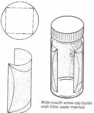
A convenient developing chamber for TLC plates can be prepared from an ordinary
wide-mouthed, screw-cap bottle. The inside of the bottle is lined with a folded circle of filter paper, which
acts as a wick to transfer the developing solvent to the upper portions of the chamber. As shown in
Figure 3.1, the circle of filter paper is folded to form a rectangle, which is inserted in the wide- mouthed bottle with the folds against the walls of the bottle. The size of filter paper should be
chosen so that the folded paper comes close to the top of the bottle, but there must be a gap
between the paper and the top of the bottle so that the approach of the solvent front to the upper
line on the plate can be seen without removing the cap. Sufficient solvent is added to the bottle to
saturate the liner and leave a layer 2-4 mm deep at its shallowest point. The spotted end of the
plate is centered in the bottom of the chamber with its upper edge leaning against the wall; the
spotted face of the plate should face the gap in the filter paper lining so that the rising spots will be
visible. The bottle is capped and gently set aside until the rising solvent front has just reached the
upper line. The plate is then removed and the solvent is allowed to evaporate from it. Since the
solvent vapors may be harmful, it is good practice to do the evaporation in a hood.
If one or more of the components to be identified is colorless, a convenient visualization
technique is to place the plate in another screw-cap bottle containing a few crystals of iodine mixed
with about. a table spoon of sand which serves to disperse the iodine. The capped bottle is held
horizontally and rotated for a few seconds to bring the plate in contact with the iodine and sand
mixture. Iodine vapor is absorbed on the plate wherever there is a concentration of organic material
and produces a brown spot (commercial plastic plates do not absorb a significant amount of iodine
under these conditions; some organic compounds also do not absorb iodine vapor). After the color
has developed, the plate is removed and a circle penciled around each spot. On exposure to air,
the brown iodine spots gradually evaporate.
Another method for visualization, which works with compounds that absorb ultraviolet (UV)
light, is to use thin-layer plates that have been impregnated with a fluorescent dye. When the plate
is exposed to UV light, the dye will glow; if the organic compound absorbs UV light, it will prevent
1 0
the light from reaching the dye and make a dark spot at that point against the glowing background.
While the plate is glowing, the dark spots should be circled carefully with a pencil so that their
positions can be measured and recorded after the ultraviolet light has been withdrawn. When
handling the UV lamp, take care to avoid looking directly at the light source because unfiltered UV
light could damage your eyes.
Figure 3.1 Developing Chamber for Thin-Layer Chromatography
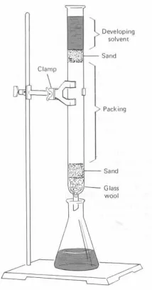
III.1.2.2 Column Chromatography
A simple apparatus for liquid-solid column chromatography is a glass tube that has been
constricted at one end (Figure 3.2). For separation of 0.1- to 0.5-g samples, a convenient tube size
is 60 cm of 15-mm diameter tubing. This size will hold about 50 g of solid support and give a 100: 1
ratio of packing to sample. Other sample sizes may be used with appropriately scaled apparatus.
III.1.2.3 Pencil Columns
When you are working with only a few milligrams of sample, the column just described is
much too large. TLC could be used, but an interesting option is to do column chromatography with
a Pasteur pipet for the column. A small wad of glass wool is pushed into the constricted neck of the
pipet, followed by enough adsorbent to produce a column about 3-5 cm high. The sample and
solvent are added in the way described previously. Frequently, the solvent will not flow through the
column on its own and must be forced through (slowly) with a rubber bulb.
1 1
III.1.3 Procedure
III.1.3.1 Separation of Ink Pigments by Thin-Layer Chromatography
Prepare two 2x 10-cm thin-layer plates by drawing two horizontal pencil lines across each
plate 7 mm from each end. On the bottom line of each plate, about 5 mm from the left-hand edge,
make a single, sharp dot of ink from a black Flair pen; in the center of the line make a second spot
about 2 mm in diameter by momentarily holding the pen tip on the plate; on the right-hand side of
the line, about 5 mm from the edge, make a third spot about 5 mm in diameter. Add sufficient
acetone to an 8-oz, wide-mouth, screw-cap bottle containing a filter paper lining until a 3-mm-deep
layer is produced. Center one of the spotted plates in the bottle with the upper edge leaning against
the side and screw the cap tightly onto the bottle. When the solvent front reaches the upper pencil
line, remove the plate and allow the solvent to evaporate. While the first plate is developing, repeat
the process with the other plate and a second 8-oz bottle using a 1 : 1 mixture of acetone and 95%
ethanol.
Determine and record the Rf values for all of the colored spots. Determine which spots, if
any, are UV active. Determine which spots are stained by I2. Make a sketch of the two plates in
your laboratory notebook showing the location and shape of the spots with side notes on their
response to UV and I2 .
The experiment can be repeated with other colors of Flair pens to determine if the same dyes are
used that were found in the analysis of the pen with black ink.
Figure 3.2 Apparatus for Column Chromatography
1 2
III.1.3.2 Separation of Plant Pigments by Thin-Layer Chromatography
In a mortar place 1 g of spinach, 1 g of clean sand, 5 mL of acetone, and 5 mL of mixed
"hexanes." Grind the spinach until the green chlorophyll appears to have been extracted
completely. Decant the solution into a small beaker.
Prepare two thin-layer plates as described in (A) and in the center of each bottom line place a
microdrop of the chlorophyll extract. Blow gently on the spot so that the solvent evaporates quickly.
Repeat the addition of the extract several times until a distinct green spot is visible. The additions
should superpose as closely as possible.
Develop one plate with 1: 4 (v: v) mixture of acetone and mixed "hexanes"s as described in (A).
Develop the second plate with a 1: 6: 1 (v: v: v) of aceton, mixed hexanes and etanol 95%.
III.1.3.3 Separation of a Dye Mixture
Insert a small wad of glass wool into the constricted end of a 30-cm length of 10-mm
diameter tubing and clamp the tube in an upright position (see Figure 3.2). Add a 5-mm layer of
coarse sand to the tube. Ina 100-mL beaker, prepare a slurry of 6 g of aluminum oxide in 10 mL of
hot water, and transfer the slurry in small batches to the tube (swirl between additions). The water
that filters through the sand and glass wool should be collected and used to transfer any column
material that remains in the beaker. After the packing has settled, add a second 5-mm layer of
sand, followed by a small filter paper circle.
When the last drop of water penetrates the column, add 4 drops of the dye solution to the
top of the column. When the dye solution has penetrated, add a few drops of water to wash down
any dye adhering to the walls. After the wash water has penetrated, fill the tube with water and
allow the chromatogram to develop.
III.1.4 Questions
1. Arrange the following compounds in the order of their elution from a silica gel column, with
benzene as eluent.
CH3(CH2)10CH3 CH3CO2H CH3CH2CH2OH CH3COCH2CH3
2. Suggest suitable liquid phases for separation of carboxylic acids by liquid-liquid
chromatography.
3. Lists several classes of solvents arranged in order of increasing eluting ability. Give a practical
example of each class.
1 3
E X P E R I M E N T 4
IV.1 D
I S T I L L A T I O N
IV.1.1 Introduction
Distillation is the most important means of separating and purifying liquid compounds on a
large scale. It consist of vaporizing the liquid and condensing the vapor in a separate receiver.
There are several kinds of distillation processes ; simple, fractional, steam and distillation under reduced pressure. Simple distillation will be discussed first since it depends upon principles and
concepts which will be needed to understand the other techniques.
Distillation consists of boiling a liquid and condensing the vapor in such a manner that the
condensate (distillate) is collected in a separate container. A simple apparatus assembly for this
operation is shown in Figure 4.1. When a pure substance is distilled at constant pressure, the
temperature of the distilling vapor will remain constant throughout the distillation provided that
sufficient heat is supplied to ensure a uniform rate of distillation and superheating is avoided. In
actual practice these ideal conditions are not obtained; drafts in the laboratory can cause
momentary condensation of vapors before they reach the thermometer, which lowers the
temperature sensed by the thermometer. On the other hand, after they leave the surface of the
liquid the distilling vapors may be heated above the liquid's boiling point (superheating), which
increases the temperature sensed by the thermometer. Because of these two contrary effects, a
distillation range of 1-20 actually represents an essentially constant boiling point. With somewhat
more refined apparatus and technique, a distillation range of 0.10 can be observed for a pure
compound.
The temperature reading of a thermometer in the distilling vapor represents the boiling
point of that particular portion of the distillate. This temperature will be the same as the boiling point
of the liquid in the distilling flask only if the distilling vapor and the boiling liquid are identical in
composition. Since a pure liquid fulfills this condition, a constant thermometer reading is sometimes
used as a criterion of purity of a liquid. It should be noted, however, that certain mixtures (such as
azeotropes) also give constant thermometer readings. Occasionally two liquids have such similar
boiling points that no appreciable change in the thermometer readings will be observed when a
mixture of them is distilled.
1 4
Figure 4.1 Apparatus for Simple Distillation
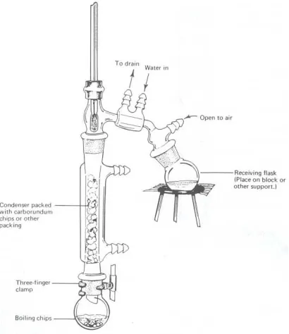
IV.1.2 Fractional Distillation
The common use of the term fractional distillation refers to a distillation operation in which
a fractionating column has been inserted between the boiler and the vapor takeoff to the
condenser. The effect of this column is to give in a single distillation a separation equivalent to
several successive simple distillations (Figure 4.2).
Figure 4.2 Apparatus Fractional Distillation
1 5
In addition to packed columns, special columns are available that achieve; mixing of the
ascending vapor and the descending condensate by their special construction. One of the simplest,
least expensive, and most widely used is the Vigreux column (Figure 4.3). It is essentially an empty
tube with many finger-like indentations that point downward at a 450 angle. The rising vapors
condense on the fingers and any excess liquid drips down to lower parts of the column. The film of
condensate on each finger equilibrates with the rising vapor. Under normal working conditions the
Vigreux column has a relatively low efficiency (high HETP of 10 cm), but its low resistance to vapor
flow permits a large throughput (volume of distillate per unit of time) that makes the column well
suited to distillation of bulk solvents. Because of its small surface area the column has a low holdup
and is sometimes used for preliminary purification of small samples.
Figure 4.3 Vigreux Column
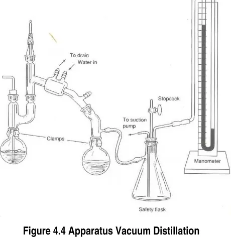
IV.1.3 Vacuum Distillation
Since the boiling temperature of a liquid is decreased by diminishing the pressure on its
surface, you can distill at a lower temperature by using an apparatus that is connected to a vacuum
pump that maintains a lower inside pressure. This procedure is useful for Purifying liquids (or
low-melting solids) that decompose at elevated temperatures (Figure 4.4).
IV.1.4 Steam Distillation
Steam distillation consists of distilling a mixture of water and an insoluble or partly soluble
substance. The practical advantage of steam distillation is that the mixture usually distills at a
temperature below the boiling point of the lower-boiling component. Consequently, it is possible to
steam distill a high boiling organic compound at a temperature much below its boiling point (in fact,
below 100°) without resortin, to vacuum distillation. Steam distillation is useful also in separating
mixtures when one component has an appreciable vapor pressure (at least 5 mm) in the vicinity of
100° and the other has a negligible vapor pressure. The process of steam distillation is widely
1 6
employed in the laboratory and in industry; e.g., for the isolation of a-pinene, aniline, nitrobenzene,
and many natural essences and flavoring oils (Figure 4.5).
Figure 4.4 Apparatus Vacuum Distillation
Figure 4.5 Small-Scale Steam Distillation Assembly
1 7
IV.1.5 Laboratory Practice
The purpose of this section is to provide sufficient practice in purification of liquids by
distillation so that this operation can subsequently be carried out skillfully and without reference to
detailed directions. Usually only one or two of these procedures will be assigned.
IV.1.5.1 Simple Distillation
Arrange a distillation assembly similar to the one shown in Figure 4.1.
Distillation of a Pure Compound
Into the 250-mL boiling flask introduce 100 mL of pure methanol (caution- flammable
liquid) by means of a clean, dry funnel. Add one or two tiny boiling chips, attach the boiling flask,
and make certain that all connections are tight. Place a graduated cylinder beneath the drip tip to
serve as receiver. Heat the flask gently until the liquid begins to boil. Adjust the heating rate until
the ring of vapor condensation moves up the wall of the flask and past the thermometer into the
condenser. Record the temperature when the first few drops of distillate are collected. Continue to
distill the liquid slowly (not over 2 mL/min) and record the distilling temperature at regular intervals
during the distillation when the total distillate amounts to 1, 2, 3, etc., mL. Discontinue the
distillation (and turn off the heat source) when all but 1 mL of the liquid has distilled. Record the
temperature range from the beginning to the end of the distillation; this is the observed boiling
point. If the boiling point differs from the literature value, record the correction in your laboratory
notebook for future reference.
Transfer the used methanol to a bottle provided for this purpose. From your data, draw a
distillation graph for pure methanol, plotting distilling temperatures on the vertical axis against total
volume of distillate on the horizontal axis.
IV.1.5.2 Fractional Distillation
Arrange an assembly for fractional distillation as shown in Figure 4.2.
(A) Methanol and Water
For the separation of a 50:50 mixture (by volume) of methanol and water, the following temperature
ranges are satisfactory for the fractions: A, 64-70; B, 70-80; C, 80-90; D, 90-95; and E, residue.
Plot your data for the distilation temperature versus volume distilled and by selecting the curve
closest to your data estimate the number of theoretical plates obtained.
1 8
(B) Acetic Acid and Water
In this experiment you will fractionally distill a mixture of glacial acetic acid and water (100:
31.5 by volume, 1: 1 mole ratio) and follow the progress of separation by titrating 0.5-mL portions of
several fractions against standardized aqueous sodium hydroxide with phenolphthalein indicator to
determine the acetic acid content. The acetic acid content of the original mixture should be
determined in the same way before the material is fractionated. If a column having a large number
of plates is used, it will be desirable to use larger portions of the early fractions.
Obtain a 35-mL supply of a 1 : 1 molar solution of acetic acid and water. Fill a 50-mL buret
with 1.0 N sodium hydroxide solution. With the aid of a 0.5-mL or 1.0-mL pipet, place 0.5 mL of the
1 : 1 molar solution of acetic acid and water in a 50-mL Erlenmeyer flask and add 10 mL of water
and a few drops of phenolphthalein indicator. Titrate to a slightly pink end point and record the
volume of titrant. Repeat the titration on two more 0.5-mL samples of the 1 : 1 molar solution of
acetic acid and water and compute the average titer.
Assemble a fractional distillation apparatus using a 50-mL round-bottomed flask for the
boiler and a 25-mL graduated cylinder for the receiver. Place 30 mL of the 1 : 1 mixture in the flask
and add a boiling chip. You will need a small test tube that has been marked to show the liquid
level when it contains exactly 0.5 mL of liquid.
Heat the mixture until it boils and then adjust the heating rate so that the mixture distills at
a maximum rate of 1 drop/sec. Note the temperature at which the first drop distills. Collect the first
0.5 mL of distillate in your marked test tube and the next 4.5 mL in the graduated cylinder. Record
the distillation temperatures at each 1-mL interval. Transfer the 0.5-mL sample to a 50-mL
Erlenmeyer flask (rinse the tube with a total of 10 mL of distilled water and add the rinse to the
Erlenmeyer flask). Mark the flask to indicate the sample it contains.
When the volume of distillate reaches 5 mL, collect another 0.5-mL sample in the test tube
and transfer it in the same manner to another Erlenmeyer flask. Collect the next 4.5 mL of distillate
in the graduated cylinder, recording the distillation temperatures at each 1-mL interval. Repeat this
process at 10 mL, 15 mL, 20 mL, and 25 mL of distillate. Titrate the six samples with the sodium
hydroxide solution (the early samples will require very little titrant) and calculate the mole fraction of
acetic acid present. In the calculations assume that the volumes of acetic acid and water are
additive so that the mole fraction in any sample is simply proportional to the titer value obtained for
the initial 0.5 mole fraction mixture.
1 9
Prepare a plot of boiling point (ordinate) versus the total volume of distillate (abscissa) and a
second plot of the mole fraction of acetic acid versus the total volume of distillate.
IV.1.6 Questions
1. (a) Define boiling point in terms of vapor pressure.
(b) What effect does a reduction of external pressure have upon the boiling point?
2. What effect on the temperature of a boiling liquid and on its distillation temperature is
produced by each of the following?
(a) a soluble, nonvolatile impurity
(b) an insoluble, admixed substance such as sand or fragments of wood or cork
3. Why should a distilling flask at the beginning of a distillation be filled to not more than two
thirds of its capacity but filled to not less than one third of its capacity?
4. Why is the apparatus shown in Figure 4.1 not suitable for distillation of samples with a
volume of 5 mL or less?
5. Why is it dangerous to heat an organic compound in a distilling assembly that is closed
tightly at every joint and has no vent or opening to the atmosphere?
6. (a) What is an azeotropic mixture?
(b) Why cannot its components be separated by fractional distillation?
IV.2 R
E F R A C T I V E
I
N D E X
IV.2.1 Introduction
A beam of light appears to bend as it passes from one medium to another. For example,
when viewed from above an oar looks bent at the point where it enters the water. This effect is a
consequence of the refraction of light. It results from the change in velocity of the radiation at the
interface of the media, and the angle of refraction, If >'. It is related to the velocity change as
follows:
sin Φ = velocity in vacuum = n (refractive index)
sin Φ velocity in sample
where Φ is the angle of incidence between the beam of light and the interface. Because the
velocity of light in a medium must be less than that in a vacuum, the index of refraction n will
2 0
always be greater than 1. In practice, n is taken as the ratio of the velocity of light in air relative to
the medium being measured.
The refractive index is also wavelength dependent. The wavelength dependence gives
rise to the effect of dispersion or the spreading of white light into its component colors. When we
measure n, therefore, we must specify the wavelength at which the measurement is made. The
standard wavelength for refractive index determinations has become the (yellow) sodium 589-nm
emission, the sodium D line. Sodium, unfortunately, is a poor choice of wavelength for these
measurements with organic substances. In the past, however the sodium lamp represented one of
the easiest to obtain monochromatic sources of light and thus it became widely used. Because the
density of the medium is sensitive to temperature, the velocity of radiation also changes with
temperature, so refractive index measurements must be made at constant temperatures. Many
values in the literature are reported at 20 °C. The refractive index can be measured optically quite
accurately to four decimal places. Because this measurement is particularly sensitive to the
presence of impurities, the refractive index can be a valuable physical constant for tracking the
purification of liquid samples.
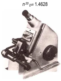
For example, the measurement is reported as
n 20 D= 1.4628
Figure 4.6 Abble-3L refractometer
The refractometer is adjusted so that the field of view has a well-defined light and dark split image
(see your instrument manual for the correct routine for making adjustments on your particular
refractometer).
When using the refractometer, always clean the prisms with alcohol and lens paper before
and after use. Record the temperature at which the reading is taken. A reasonably good
2 1
extrapolation of temperature effects can be obtained by assuming that the index of refraction
changes 0.0004 unit per degree Celsius, and that it varies inversely with temperature.
IV.2.2 Procedure
In the Abble-3L refractometer (Fig. 4.6), white light is used as the source, but
compensating prisms give indexes for the D line. This refractometer is commonly used in many
organic laboratories. Samples (Distillation product) (~10 µL) are applied between the horizontal
surfaces of a pair of hinged prisms. A sampling procedure recently developed by Ronald
significantly reduces the amount of sample required and allows accurate measurements of highly
volatile materials. The technique involves placing a small precut 6-mm disk of good-quality lens
paper at the center of the bottom prism. The sample is loaded onto the disk with a micro Pasteur
pipet or microliter syringe.
2 2
E X P E R I M E N T 5
V.1 F
U N C T I O N A L
G
R O U P
I
D E N T I F I C A T I O N
V.1.1 Introduction
Any compound other than a saturated hydrocarbon has at least one functional group,
which can be identified by carrying out a series of "classification tests" that serve to narrow the
range of possibilities until only one remains. When the functional group is identified, an appropriate
table of characterized compounds containing this group is consulted, and those compounds having
chemical and physical properties consistent with the sample are selected. In favorable cases only a
few compounds will be found; rarely will there be more than 10.
The lists of compounds containing each functional group give not only the physical
properties of the molecules but also the properties of solid substances (derivatives) that can be
prepared from it by tested procedures. Since the melting points of these derivatives are usually
distinctive, the combination of properties of the original substance and of its derivatives is sufficient
to identify it. The list of functional groups is restricted but does include the most commonly
encountered types.
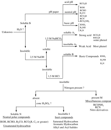
In the laboratory it is important to perform the classification tests in a sequence consistent
with the accumulated evidence, never at random. A good guide is the solubility classification
scheme (Figure 5.1), which lists the possible functional groups for each solubility class. For
example, if the elemental analysis reveals nitrogen and the compound falls in solubility class B, the amine tests should be performed directly.
As a second example, if a neutral compound falls in class S or N and does not contain
nitrogen, sulfur, or halogens, the functional group must be one of the following: alcohol, aldehyde,
ketone, or ester. In this case, the recommended next step is to test with 2,4-dinitrophenylhydrazine
for an aldehyde or ketone. If the test result is positive, further structural distinctions can be made
with the tests described in the procedures for aldehydes and ketones. A negative
2,4-dinitrophenylhydrazone test should be followed by the hydroxamate test for esters. If that test is
negative, only the alcohol class remains, and this can be confirmed by the classification tests for
alcohols. Functional groups of compounds that fall into other solubility classes can be identified by
analogous strategies.
2 3
To ensure satisfactory results for the tests, we recommend that the specified quantities of
liquid reagents be measured in a graduated cylinder or a calibrated dropper. If a test is being done
for the first time, it is a good idea to practice on materials of known structure.
Infrared (IR) analysis is a powerful tool for identifying functional groups because a single IR
spectrum reveals much about the nature of all of the fuctional groups present. However, the IR
spectrum usually does not provide a total answer and one must resort to either other instrumental
techniques or the chemical methods described here.
Soluble S
Insoluble Unknown
H2O ?
pH paper
acid pH
neutral pH
basic pH
RCO2H ROH RCHO
RCO2R
RCN RCO2NH2
RNH2
2,5 M NaOH soluble
insoluble
1,5 M NaHCO3
Strong acid
Nitrogen present ?
RCO2H
RCN Nitro derivatives RCONH2 Miscellaneous compounds present M RNH2 absent
R2NH R3N
soluble A1
insoluble A2
RSO3H
some phenol
Weak Acid Most phenol
1,5 M HCl
soluble B
Basic Compounds
insoluble
conc H2SO4 ?
Soluble N
Unsaturated hydrocarbon
(ROH, RCHO, R2CO, RCO2R, C5 or greater) Neutral polar compounds
Insoluble I
Aromatic Hydrocarbon Alkyl and Aryl halides Saturated Hydrocarbon
Inert compounds
R2CO
R2NH R3N
Figure 5.1 The Solubility Classification Scheme
2 4
V.1.2 Alcohols
The tests described are used to distinguish amoung primary, secondary, and tertiary
alcohols. The tests also can yield information about the structure surrounding the carbon bearing
the alcohol functional group. The Ritter test is a general test for alcohols or other readily oxidizable
functional groups such as aldehydes. The Lucas test and the iodoform test provide further
structural information about the alcohol.
V.1.2.1 Ritter Test
This test, based on the ability of primary and secondary alcohols to be oxidized by an
acetic acid solution of potassium permanganate, distinguishes these alcohols from tertiary alcohols.
The permanganate ion is purple, but when reduced the color changes to brown; a positive test is
the disappearence of the purple color.
To 3 mL of glacial acetic acid (caution-corrosive!) contained in a small test tube, add 2
drops of your liquid unknown (or about 20 mg of a solid) and mix thoroughly. Add dropwise, with
swirling to mix the contents after each addition, a saturated aqueous solution of potassium
permanganate and note any change in the color of the solution. If the alcohol is tertiary, the purple
permanganate color will persist as a rose color after 1 or 2 drops have been added. If the alcohol is
primary or secondary, the solution will decolorize the permanganate and remain clear until
sufficient permanganate has been added to oxidize all of the alcohol. Remember that the Ritter test
probes the oxidizability of the unknown; if the unknown contains another readily oxidized functional
group such as an aldehyde or alkene, the test will also be positive even in the absence, of an
alcohol.
As with all chemical reaction tests it is prudent to try the test on compounds l known to give both a
positive (a primary or secondary alcohol) and a negative (tertiary alcohol) result.
V.1.2.2 Lucas Test
The reagent used is concentrated hydrochloric acid containing I mole of anhydrous zinc
chloride to 1 mole of the acid. The Lucas test distinguishes between primary, secondary, and
tertiary alcohols and is based on the rate of formation of the insoluble alkyl chloride. To be reliable
the alcohol should be soluble in water (class S).
The ease of conversion of alcohol to chloride follows the stability of the corresponding carbocation,
modified by the solubility of the alcohol in the test reagent. Allyl alcohol, CH2=CH-CH2OH, which
yields a stabilized charge delocalized cation acts like a tertiary alcohol. Isopropyl alcohol
2 5
sometimes fails to give a positive test because the chloride product is volatile (36°) and may
escape from the solution.
To 0.5 mL of the alcohol add quickly 3 mL of the hydrochloric acid-zinc chloride reagent at
,room temperature. Close the tube with a cork and shake it; then allow the mixture to stand.
Tertiary alcohols give an immediate separation (emulsion) of the chloride, secondary alcohols
require about 5 min, but most primary alcohols do not react significantly in less than an hour. If the
result is positive, carry out a second test using concentrated hydrochloric acid alone, instead of the
test reagent. This less reactive reagent will give chloride emulsions within 5 min only with tertiary
alcohols.
V.1.2.3 Iodoform Test
This is a test for the specific structural feature R-CHOH-CH3 (R may also be H). The test
depends on initial oxidation of the alcohol to R-CO-CH3, which is iodinated and then cleaved to give
a bright yellow precipitate of iodoform.
In a clean (acetone-free) 150-mm test tube mix 3 drops of the liquid (or about 50 mg of
solid) with 2 mL of water and 2 mL of 10% aqueous sodium hydroxide solution. Add dropwise, with
shaking, a 10% solution of iodine in potassium iodide until a definite brown color persists (indicating
an excess of iodine).
With some compounds a precipitate of iodoform appears almost immediately in the cold. If it does
not appear within 5 min, warm the solution to 60° in a beaker of water. If the brown color is
discharged, add more of the iodine solution until the iodine color persists for 2 min. Add a few drops
of sodium hydroxide solution to remove excess iodine, dilute the mixture with 5 mL of water, and
allow it to stand for 5 min at loom temperature.
For compounds that are not appreciably soluble in water, the sample may be dissolved in
pure methanol instead of water. Before starting the test the solvent should be tested to see if
iodoform-producing impurities are present.
Iodoform crystallizes as lemon yellow hexagons having a characteristic odor. Their identity can be
confirmed by collecting it with suction and taking the melting point (119°).
V.1.3 Aldehydes and Ketones
The 2,4-dinitrophenylhydrazone test is positive for both aldehydes and ketones. These
may be distinguished by either the silver mirror test, which depends on the easy oxidation of
aldehydes, or the Schiffs fuchsin test, which depends on the ease of formation of SO2 adducts of
2 6
aldehydes but not ketones. Another test that will distinguish aldehydes from ketones is the chromic
acid test, described earlier under alcohols.. Aromatic aldehydes take about 60 sec to give a positive
test.
The iodoform test, also described earlier under alcohols, is specific for molecules containing a
methyl group adjacent to a carbonyl group or to any other structure that can form such a methyl
carbonyl combination. The only aldehyde that gives a positive iodoform test is acetaldehyde.
V.1.3.1 2,4-Dinitrophenylhydrazone Test
Most aldehydes and ketones react with 2,4-dinitrophenylhydrazine reagent to give
precipitates of the 2,4-dinitrophenylhydraones. Esters and amides generally do not respond and
can be eliminated on the basis of this test. The color of the precipitate depends on the degree of
conjugation in the aldehyde or ketone. Unconjugated aliphatic carbonyl groups such as butanal or
cyclohexanone give yellow precipitates.
Conjugated carbonyls, such as benzaldehyde or methyl vinyl ketone, give red precIpItates.
Unfortunately, the reagent is orange-red; one should establish that a reddish precipitate is really a
new product and not just the starting reagent that has been made insoluble by the addition of the
unknown.
In a clean small test tube, place 1 mL of 2,4-dinitrophenyl-hydrazine reagent and add a few drops
of liquid (or about 50 mg of solid dissolved in the minimum amount of 95% ethan