SKRIPSI – ME141501
SISTEM MONITORING SUHU TERINTEGRASI
BERBASIS WIRELESS SENSOR NETWORK DI REEFER STORAGE
Ardian Yudha NRP 4211 100 002
Dosen Pembimbing
Sutopo Purwono Fitri, S.T, M.Eng, Ph.D Ir. Alam Baheramsyah, M.Sc
JURUSAN TEKNIK SISTEM PERKAPALAN FAKULTAS TEKNOLOGI KELAUTAN
INSTITUT TEKNOLOGI SEPULUH NOPEMBER SURABAYA
FINAL PROJECT – ME141501
INTEGRATED TEMPERATURE MONITORING SYSTEM BASED ON WIRELESS SENSOR NETWORK IN REEFER STORAGE
Ardian Yudha NRP 4211 100 002
Supervisors
Sutopo Purwono Fitri, S.T, M.Eng, Ph.D Ir. Alam Baheramsyah, M.Sc
DEPARTMENT OF MARINE ENGINEERING FACULTY OF MARINE TECHNOLOGY
SEPULUH NOPEMBER INSTITUTE OF TECHNOLOGY SURABAYA
vii STORAGE
Nama : Ardian Yudha
NRP : 4211 100 002
Dosen Pembimbing 1 : Sutopo Purwono F, ST., M.Eng., Ph.D Dosen Pembimbing 2 : Ir. Alam Baheramsyah, M.Sc
ABSTRAK
Semakin meningkatnya jumlah distribusi produk hortikultura yang mudah membusuk, semakin meningkat pula penggunaan kapal kontainer berpendingin (reefer storage). Hal ini dibutuhkan untuk menjaga suhu buah dan sayuran sesuai kebutuhan. Di dalam industri cold chain, banyaknya tahap dan lamanya waktu penyimpanan dan pendistribusian menyebabkan ketidakstabilan suhu, sehingga perlu adanya monitoring suhu secara periodik, terutama di dalam reefer storage. Hal ini dilakukan untuk menjaga kesegaran dan kualitas dari produk. Di dalam penelitian ini, Wireless Sensor Network (WSN) digunakan sebagai salah satu inovasi sistem monitoring suhu.
Penelitian ini bertujuan untuk mengadakan percobaan dan menganalisa efektifitas sistem monitoring suhu menggunakan Wireless Sensor Network dibandingkan dengan sensor temokopel, serta mengidentifikasi lokasi sensor suhu di dalam reefer storage berdasarkan perencanaan peletakan kargo. Penelitian ini menggunakan pisang sebagai kargo yang harus dijaga suhunya antara 12 – 16 oC. Percobaan pertama menggunakan sensor termokopel tipe K dan data logger Labjack T7 Pro. Percobaan kedua menggunakan beberapa sensor node, koordinator, repeater, dan modul penerima.
viii
mengacu pada nilai standard error selama proses kalibrasi. Di lain pihak, sensor termokopel mampu membaca 7,200 data suhu secara real-time. Sebagai tambahan, lokasi-lokasi kritis di dalam reefer storage terdapat pada sisi atas dan tengah dari kargo. Berdasarkan hal-hal tersebut, implementasi Wireless Sensor Network di dalam reefer storage akan lebih efektif dibandingkan dengan sensor termokopel dalam hal kemampuan monitoring secara real-time yang sama serta dalam hal jangkauan transmisi data dari sensor ke modul penerima yang sejauh 100 meter.
v STORAGE
Name : Ardian Yudha
NRP : 4211 100 002
Supervisor 1 : Sutopo Purwono F, ST., M.Eng., Ph.D Supervisor 2 : Ir. Alam Baheramsyah, M.Sc
ABSTRACT
The increasing number of perishable horticultural product distribution leads to the increasing number of the use of reefer storage/container vessels. It is needed to keep the temperature suitable for fruits and vegetables. In the cold chain industry, some steps and long time needed in the storing and distribution process cause unstable temperature, so the periodical temperature monitoring is needed, especially in vessels’ storages. This is done in order to maintain the freshness and quality of the products. In this study, a Wireless Sensor Network (WSN) was implemented as one of the monitoring systems.
This study was aimed to conduct experimentally and analyze the effectiveness of the temperature monitoring system using Wireless Sensor Network compared to the thermocouple sensors, as well as to identify the location of the temperature sensors in the reefer storage based on the stowage plan. This study was based on the setting temperature of bananas around 12 – 16 oC. The first experiment used thermocouple sensors type K and Labjack T7 Pro data logger. The second experiment used WSN sensor nodes, the coordinator, the repeater, and the receiver module.
vi
in the calibration process. On the other hand, thermocouple sensors could read 7,200 temperature data completely and real-time. In addition, the critical locations in reefer storage were on the top side and middle side of the cargo. Based on these findings, the implementation of Wireless Sensor Network in reefer storage was found to be more effective than thermocouple sensors in terms of the similar capability to monitor real-time data and of the range of the data transmission from the sensors to the receiver which is around 100 meters.
ix
Alhamdulillah. All praises to The Almighty God, Allah SWT, for always bestowing His best blessings for me to get this research done.
Foremost, I wish to express my sincere gratitude to Mr. Sutopo Purwono Fitri, S.T, M.Eng, Ph.D, my first research supervisor as well as my academic advisor, for the continuous support of my bachelor study and research, for his patient, motivation, enthusiasm, and immense knowledge. I place on record, my sincere thank you to Mr. Ir. Alam Baheramsyah, M.Sc, my second research supervisor, for the continuous encouragement. Their guidance helped me in all the time of research and writing of this thesis.
Besides my supervisors, I would like to thank the rest of my thesis examiners: Mr. Ir. Soemartojo WA, Mr. Ir. Hari Prastowo, M.Sc, Mr. Taufik Fajar Nugroho, S.T, M.Sc, and Mr. Beny Cahyono, S.T, M.T, for their valuable guidance, hard questions, and constructive feedbacks during the process and examination of this thesis.
An enormous amount of gratitude and love is awarded to my dearest Kartoyudho Family and Sudiro Family, though that would not be enough compared to their never-ending love, pray, and support. I also take this opportunity to thank you to Yolanda Putri Yuda, my sister in crime, for helping me and positively supporting me.
The last but not least, thank you so much to Arlita Alif Viany for spending her time proofreading this thesis, Moch. Qusyairi and Fayun Bondan Maghfiroh for being my good research mates, Emmy Pratiwi and Taufiqurrahman for kindly
helping me during my process, and all lab mates and AMPIBI’11
xi
APPROVAL SHEET……….... ... i
ABSTRACT ... v
ABSTRAK ... vii
ACKNOWLEDGEMENTS ... ix
TABLE OF CONTENT ... xi
ILLUSTRATION ... xv
TABLE ... xvii
CHAPTER I INTRODUCTION ... 1
1.1 Background of the Study ... 1
1.2 Research Problems ... 2
1.3 Scope of the Study ... 2
1.4 Research Objectives ... 3
1.5 Research Benefits ... 3
CHAPTER II THEORITICAL FRAMEWORK ... 5
2.1 Paper Review ... 5
2.2 Reefer Storage ... 6
2.3 Reefer Storage’s Working Principle ... 8
2.3.1 Compression ... 8
2.3.2 Condensation ... 8
2.3.3 Expansion ... 8
2.3.4 Evaporation ... 9
2.4 Cold Chain ... 9
2.5 Cooling Temperature of Horticultural Products ... 10
2.6 Wireless Sensor Network (WSN) ... 14
2.7 Application of Wireless Sensor Network (WSN) ... 15
2.8 Components of Wireless Sensor Network ... 18
2.9 Working Principle of Wireless Sensor Network ... 18
xii
2.13 Processing Analog-Digital Converter ... 24
2.14 Formula for Voltage-Temperature Value Conversion .... 24
2.15 Stowage ... 26
CHAPTER III RESEARCH METHODOLOGY ... 29
3.1 Study of Literature ... 29
3.2 Empirical Studies of Wireless Sensor Network (WSN) & Thermocouple ... 29
3.3 Experiment of Temperature Monitoring System Based on WSN Method ... 30
3.4 Experiment of Temperature Monitoring System Based on Thermocouple Sensors ... 31
3.5 Data Analysis ... 31
3.6 Method Comparison ... 32
3.7 Conclusion ... 32
3.8 The Flow Chart of the Research Methodology ... 33
3.9 The Experiment Plot of Wireless Sensor Network Method ... 34
3.10 The Experiment Plot of Thermocouple Sensors Method 34 CHAPTER IV RESEARCH PREPARATION AND PROCESS ... 35
4.1 Experimental Apparatus ... 35
4.1.2 Cold Storage ... 35
4.1.3 WSN Apparatus ... 36
4.1.4 Thermocouple Apparatus ... 36
4.2 Data Collection Methods ... 36
4.2.1 Data Collection Method Based on Thermocouple Sensors ... 37
4.2.2 Data Collection Method Based on Wireless Sensor Network ... 37
xiii
4.4.2 Installation & Configuration of Data Logger ... 40
4.4.3 An Initial Data Collection for Data Logger Calibration ... 43
4.4.4 Temperature Data Conversion ... 43
4.5 Experiment Preparation of Wireless Sensor Network... 46
4.5.1 WSN Apparatus Installation ... 46
4.6 Apparatus Calibration ... 50
4.7 Stowage Plan and Stuffing ... 51
4.8 Thermocouple Sensors and Sensor Nodes Placement... 53
4.9 Air Flow Rate Measurement ... 56
4.10 Experimental Procedure of Temperature Monitoring Based on Thermocouple Sensors ... 58
4.11 Experimental Procedure of Temperature Monitoring Based on Wireless Sensor Network ... 59
4.12 Star Topology of the WSN Experiment ... 60
CHAPTER V RESEARCH FINDINGS AND DATA ANALYSIS ... 63
5.1 Results of Apparatus Calibration ... 63
5.2 Findings of Experiment Based on Thermocouple Sensors (Monitoring 1) ... 68
5.3 Findings of Experiment Based on Thermocouple Sensors (Monitoring 2) ... 72
5.4 Findings of Experiment Based on Wireless Sensor Network (WSN) ... 74
5.5 Analysis of the Critical Location Based on Experiment Using Thermocouple ... 76
5.6 Analysis of Humidity Based on Experiment Using Wireless Sensor Network ... 78
5.7 Analysis of the Selection of WSN Apparatus ... 81
xiv
6.1 Conclusions ... 87
6.2 Suggestions ... 88
REFERENCES ... 89
APPENDICES ... 91
xv
Figure 2.1 Cold Storage Refrigeration System Piping Diagram 6
Figure 2.2 Cold Chain Process ... 10
Figure 2.3 Bus Topology ... 19
Figure 2.4 Star Topology ... 20
Figure 2.5 Tree Topology ... 20
Figure 2.6 Ring Topology ... 21
Figure 2.7 Mesh Topology ... 22
Figure 2.8 Thermocouple ... 22
Figure 2.9 Thermocouple ... 23
Figure 2.10 Interpolation Method ... 25
Figure 2.11 Incorrect-stuffing of the Container Cargo ... 27
Figure 2.12 Correct-stuffing of the Container Cargo ... 27
Figure 2.13 Top View of Cargo Stuffing ... 28
Figure 3.1 The Flow Chart of the Research Methodology ... 33
Figure 3.2 The Experiment Plot of Wireless Sensor Network Method ... 34
Figure 3.3 The Experiment Plot of Thermocouple Sensors Method ... 34
Figure 4.1 Cold Storage at MMS’s Workshop ... 35
Figure 4.2 Thermocouple Scheme ... 37
Figure 4.3 Wireless Sensor Network Scheme ... 38
Figure 4.4 Apparatus Installation of Experiment Using Thermocouple ... 40
Figure 4.5 Main Display of Select Devices at Kipling ... 40
Figure 4.6 Connectivity Display of USB Menu at Kipling ... 41
Figure 4.7 Devices Information Display at Kipling ... 42
Figure 4.8 Configuration Display at Analog Input Menu ... 42
Figure 4.9 Main Display of LJLogM ... 43
Figure 4.10 Automatic Voltage-Temperature Conversion Code . 45 Figure 4.11 WSN Apparatus Installation ... 46
Figure 4.12 Sensor Node Located in the Top Side of Cold Storage ... 47
xvi
Figure 4.16 Program GUI ... 49
Figure 4.17 Apparatus Calibration ... 50
Figure 4.18 (a) Shelf Design, (b) Cargo Stuffing Plan in Reefer Storage ... 52
Figure 4.19 Bananas as Cargo in Reefer Storage ... 53
Figure 4.20 Thermocouple Placement in the Cargo ... 54
Figure 4.21 Top View of Sensors Placement ... 54
Figure 4.22 Front View of Sensors Placement ... 55
Figure 4.23 Modification of the Evaporator ... 57
Figure 4.24 Anemometer ... 57
Figure 4.25 Labjack T7 Pro Installation during Experiment ... 58
Figure 4.26 Receiver Module Connected to the Laptop ... 60
Figure 4.27 Scheme of Star Topology ... 62
Figure 5.1 Chart of Sensors Calibration ... 64
Figure 5.2 Chart Based on Mean Data of Sensors Calibration .. 65
Figure 5.3 Chart Based on Mean Data and Standard Error of Sensors Calibration ... 67
Figure 5.4 Chart of Thermocouple-based Experiment Results .. 69
Figure 5.5 Second Monitoring Results of Thermocouple-based Experiment ... 73
Figure 5.6 Chart of WSN-based Temperature Monitoring Experiment ... 75
Figure 5.7 Air Flow Direction Released by the Evaporator ... 78
Figure 5.8 Humidity Chart of WSN Experiment ... 79
Figure 5.9 Comparison Chart between Temperature & Humidity ... 80
Figure 5.10 Comparison Chart between Node 1 and AIN 0 ... 84
Figure 5.11 Comparison Chart between Node 2 and AIN 1 ... 84
Figure 5.12 Comparison Chart between Node 3 and AIN 7 ... 85
Figure 5.13 Comparison Chart between Node 4 and AIN 3 ... 85
Figure 5.14 Comparison Chart between Node 5 and AIN 6 ... 86
Figure 7.1 WSN System with Coordinator ... 97
xvii
Table 2.1 Insulation Panel Materials ... 6 Table 2.2 Summary of Recommended CA or MA conditions
during transport and/or storage of selected fruits ... 11 Table 2.3 Summary of Recommended CA or MA conditions
during transport and/or storage of selected
vegetables ... 12 Table 4.1 Experiments Variables ... 39 Table 4.2 Voltage Data Sample ... 44 Table 5.1 Data Sample Taken from Temperature Setting 25oC 63 Table 5.2 Mean of Data Sample ... 64 Table 5.3 Table of Standard Deviation Calculation ... 66 Table 5.4 Table of Standard Deviation and Standard Error
Calculation ... 67 Table 5.5 Data Sample of Thermocouple-based Experiment
(Monitoring 1) ... 68 Table 5.6 Table of Equilibrium Time of Thermocouple
Monitoring System ... 71 Table 5.7 Data Sample of Thermocouple-based Experiment
(Monitoring 2) ... 72 Table 5.8 Temperature Data Sample of Wireless Sensor
Network (WSN)-based Experiment ... 74 Table 5.9 Comparison of Temperature Data (Right & Left
Sides) ... 76 Table 5.10 Comparison of Temperature Data (Top & Bottom
Sides) ... 77 Table 5.11 Humidity Data Sample of Wireless Sensor Network
(WSN)-based Experiment ... 79 Table 5.12 Comparison Data between IR Temperature sensor
Placed inside and outside the Cardboard ... 82 Table 5.13 Standard Error Based on Data Sample from the
First 30 Minutes ... 83 Table 5.14 Standard Error Based on Data Sample from the
1 1.1 Background of the Study
These days, the number of import and export done by local and international entrepreneurs is increasing. The increasing number of the product distribution leads to the increasing number of the use of commercial vessel transports, such as reefer storage vessels.
Reefer storage is not only used to import and export but also to distribute products in large quantity to long distance areas, such as fruits and vegetables. Because fruits and vegetables are perishable, the use of reefer container is needed in order to keep the temperature suitable for the fruits and vegetables.
The process of saving the products into containers should start from harvesting, pre-cooling, warehouse-refrigerating, and using reefer storage to distribute the products to consumers as the end users. Some steps and long time needed in the saving process cause unstable temperature, so the periodical temperature monitoring is needed, especially in vessels’ storages. This is done in order to maintain the freshness and quality of the fruits and vegetables.
The current monitoring process is mostly applying manual method, such as thermostat sensor in the containers, while we need to monitor the products periodically. Furthermore, monitoring process is not only needed by the ship operators but also other parties, especially the stakeholders related to the products, such as the distributors, markets, and shipping companies. Based on the aforementioned problems, an easily and quickly accessible monitoring method is needed.
land by using radio frequency. However, this technology costs much money, so it will increase the operational cost if we keep using it.
As a response to the aforementioned issues, we need an innovative affordable technology to easily and quickly monitor the temperature by using and developing existing technology. For instance, we can apply a wireless sensor network-based online temperature monitoring.
1.2 Research Problems
According to the background of the study, this final project has the following research problems.
1. How experiments on the temperature monitoring based on Wireless Sensor Network in the reefer storage should be conducted.
2. How the temperature sensor in the reefer storage should be placed based on the pattern of cargo stuffing.
3. How the use of temperature monitoring system by using Wireless Sensor Network is more efficient compared to thermocouple method.
1.3 Scope of the Study
According to the research problem, this final project has the following scopes.
1. The experiment is conducted only in the cold storage in the workshop of Marine Machinery and System Laboratory, Department of Marine Engineering, FTK-ITS.
2. The number of sensor nodes in the Wireless Sensor Network is equal to the thermocouple points attached in the experiment.
3. The topology used in this research is Star Topology.
5. The experiment is done to identify the monitoring system without identifying the controlling system.
1.4 Research Objectives
In accordance with the background of the study, this final project has these following objectives.
1. To conduct and to analyze the effectiveness of an experiment on the temperature monitoring system using Wireless Sensor Network based on the WSN scheme/topology.
2. To conduct an experiment on the temperature monitoring system by using thermocouple sensor as the comparison. 3. To identify the location of the temperature sensor in the reefer
storage based on the stowage planning.
1.5 Research Benefits
This final project will be able to give these following benefits.
1. In general, this final project can be used by all stakeholders in the cold chain industry, especially those who concern the cargo condition in the reefer storage by collecting real time data as the reference of the cargo quality.
5 2.1 Paper Review
Boonsawat et al. stated that Wireless Sensor Networks (WSN) is a computing technology that can be used to detect the environmental properties such as temperature, and had applied the network to the building. WSN is a combination of an embedded system with wireless communication that allows the transmission of data between the sensor nodes through ad-hoc wireless network. The applied network was used to monitor the temperature in all the classes exist in the Sirindhorm International Institute of Technology (SIIT). The purpose was to determine the energy consumption data from the use of Air Condition (AC). By applying WSN, this could be a reference to control the excessive energy consumption.
The system implemented here used XBee standards-based IEEE 802.15.4/ZigBee Wireless Personal Area Network (WPAN) by considerating the low-power, low-maintenance, and self-organizing of WSN. The simalirity of this research with the research that will be done is to take advantage of the Wireless Sensor Network technology to monitor the temperature in the room, while the difference is that WSN technology in this study was only used to monitor the temperature of the building with the aim of saving energy, while the research that will be done aims to monitor the temperature in reefer storage for controlling the temperature of fruits in it.
are cheap and widely available in the market. Based on the previous statements regarding the application of WSN for groceries storage space, the research on the application of WSN in reefer storage was appropriate.
Patil et al. described that besides being a monitoring tool, WSN could be used as a controlling tool. The application of the system was to control the temperature which had many applications such as controlling water temperature, industrial machinery tools, and within the industry itself. Next, this technology can be developed to be applied as a protection when there is a fire.
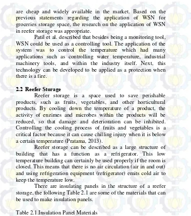
2.2 Reefer Storage
Reefer storage is a space used to save perishable products, such as fruits, vegetables, and other horticultural products. By cooling down the temperature of a product, the activity of enzimes and microbes within the products will be reduced, so that damage and deterioration can be inhibited. Controlling the cooling process of fruits and vegetables is a critical factor because it can cause chilling injury when it is below a certain temperature (Pratama, 2013).
Reefer storage can be described as a large structure of building that has a function as a refrigerator. This low temperature building can certainly be used properly if the room is closed. This means that there is no air circulation (air in and out) and using refrigeration equipment (refrigerator) emits cold air to keep the temperature low.
There are insulating panels in the structure of a reefer storage, the following Table 2.1 are some of the materials that can be used to make insulation panels.
Table 2.1.Insulation Panel Materials Panel Type U value,
W/m² °C
Weight, kg/m²
Water Adsorption Possibility
Styrofoam 0.24 13.3 0.50%
Polyurethane 0.3 13.3 2%
Mineral Wool
0.38 19 50%
Source: Pratama, 2013
Reefer Storage has these following major compenents. 1. Evaporator
2. Compressor 3. Condenser 4. Expansion Device
In addition to the aforementioned main components, reefer storage also has some some accessories, such as these following components.
1. Receiver 2. Filter Drier 3. Moisture Indicator 4. Solenoid Valve 5. Shut-off Valve
6. Pressure Gauge (LPG dan HPG) 7. Pressure Control (DPC)
Figure 2.1.Cold Storage Refrigeration System Piping Diagram Source:
2.3 Reefer Storage’s Working Principle
In its system, the cooling system has four steps of cooling process. Refrigerant is circulated repeatedly with changes to support the cooling process. Four changes in the refrigerant are compression, condensation, expansion, and evaporation (liquid, vapor, gas, and liquid back) (Purnomo, 2013).
2.3.1 Compression
In the process of compression, refrigerant is pressed in the compressor until it becomes liquid at high temperature. The refrigerant gas sucked by the compressor will make the pressure remain low in the evaporator. To make a refrigerant liquid into a gas dynamically at low temperatures (0oC), the refrigerant gas is pressed in the cylinder, and turned into high, so the temperature and pressure rise, and will easily become a liquid refrigerant although the cooling process is in higher temperatures. And the compressed refrigerant gas is supplied to the next component which is cooled in a condenser.
2.3.2 Condensation
In the process of condensation, refrigerant is changed from a gas to a liquid and cooled down from high temperature in the condenser into lower temperature. A refrigerant that has high temperature and pressure is emitted into fluid in the condenser and transmitted to the receiver dryer to be filtered. It is also called heat condensation process. High heat from the refrigerant can be released by the condenser so that refrigerant is cooled down.
2.3.3 Expansion
refrigerant’s liquid is regulated by the cooling rate which should be done under temperature carburetion. Therefore, it is important to control the amount of refrigerant needed by performing proper checks.
2.3.4 Evaporation
In the process of evaporation, refrigerant is changed from liquid to gas in the evaporator. Refrigerant’s liquid is atomized by its suction during the process of evaporation which needs latent heat from the air around the. The air released heat to be cooled down, and flowed into the space in the cold storage by the cooling fan while lowering the temperature of the room. The refrigerant’s liquid is supplied from the expansion valve in the evaporator and then once turned into refrigerant vapor, and the change occurs repeatedly from liquid to gas. The pressure and the temperature in the change are always related, if the pressure is set then the temperature will also be set. For carburetion which is done when the temperature is lower than the change (liquid to gas), in the condition as above, the pressure in the evaporator must also be made low. Therefore, the atomized refrigerant gas should be reduced continuously out of evaporator by the compressor suction.
2.4 Cold Chain
Cold Chain is included as a part of the supply chain which is aimed to keep the temperature of the products so that the products are well maintained during the distribution process. The failure of the cold chain system is a failure of the entire activity experienced by a whole series of supply chain in maintaining the temperature range according to the product (Halim, 2013).
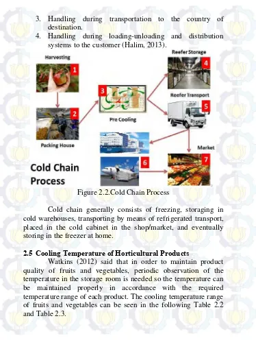
In order to get a proper cold chain system, there are four critical stages that must be observed very well in the frozen products’ cold chain system, namely:
1. Handling during the initial processing.
3. Handling during transportation to the country of destination.
4. Handling during loading-unloading and distribution systems to the customer (Halim, 2013).
Figure 2.2.Cold Chain Process
Cold chain generally consists of freezing, storaging in cold warehouses, transporting by means of refrigerated transport, placed in the cold cabinet in the shop/market, and eventually storing in the freezer at home.
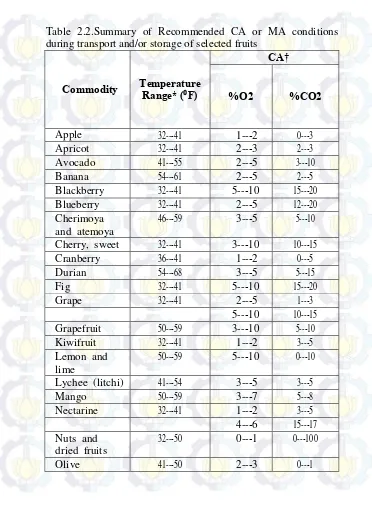
2.5 Cooling Temperature of Horticultural Products
Table 2.2.Summary of Recommended CA or MA conditions during transport and/or storage of selected fruits
Commodity Temperature Range* (⁰F)
CA†
%O2 %CO2
Apple 32--‐41 1--‐2 0--‐3
Apricot 32--‐41 2--‐3 2--‐3 Avocado 41--‐55 2--‐5 3--‐10
Banana 54--‐61 2--‐5 2--‐5
Blackberry 32--‐41 5--‐10 15--‐20 Blueberry 32--‐41 2--‐5 12--‐20 Cherimoya
and atemoya
46--‐59 3--‐5 5--‐10
Cherry, sweet 32--‐41 3--‐10 10--‐15 Cranberry 36--‐41 1--‐2 0--‐5
Durian 54--‐68 3--‐5 5--‐15
Fig 32--‐41 5--‐10 15--‐20
Grape 32--‐41 2--‐5 1--‐3
5--‐10 10--‐15 Grapefruit 50--‐59 3--‐10 5--‐10 Kiwifruit 32--‐41 1--‐2 3--‐5 Lemon and
lime
50--‐59 5--‐10 0--‐10
Lychee (litchi) 41--‐54 3--‐5 3--‐5
Mango 50--‐59 3--‐7 5--‐8
Nectarine 32--‐41 1--‐2 3--‐5 4--‐6 15--‐17 Nuts and
dried fruits
32--‐50 0--‐1 0--‐100
Orange 41--‐50 5--‐10 0--‐5
Papaya 50--‐59 2--‐5 5--‐8
Peach, clingstone
32--‐41 1--‐2 3--‐5
Peach, freestone
32--‐41 1--‐2 3--‐5
4--‐6 15--‐17 Pear, Asian 32--‐41 2--‐4 0--‐3 Pear,
European
32--‐41 1--‐3 0--‐3
Persimmon 32--‐41 3--‐5 5--‐8 Pineapple 46--‐55 2--‐5 5--‐10
Plum 32--‐41 1--‐2 0--‐5
Pomegranate 41--‐50 3--‐5 5--‐10 Rambutan 46--‐59 3--‐5 7--‐12 Raspberry 32--‐41 5--‐10 15--‐20 Strawberry 32--‐41 5--‐10 15--‐20 Sweetsop
(custard apple)
54--‐68 3--‐5 5--‐10
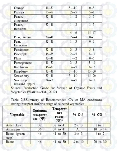
Source: Production Guide for Storage of Organic Fruits and Vegetables (Watkins et al., 2012)
Table 2.3.Summary of Recommended CA or MA conditions during transport and/or storage of selected vegetables
Vegetable Optimum temperat ure (⁰F)*
Temperat ure range
(⁰F)*
% O2† % CO2 †
Artichokes 32 32 to 41 2 to 3 2 to 3
Asparagus 36 34 to 41 Air 10 to 14
Beans (green snap)
46 41 to 50 2 to 3 4 to 7
(processing)
Broccoli 32 32 to 41 1 to 2 5 to 10
Brussels sprouts
32 32 to 41 1 to 2 5 to 7
Cabbage 32 32 to 41 2 to 3 3 to 6
Cantaloupes 37 36 to 45 3 to 5 10 to 20 Cauliflower 32 32 to 41 2 to 3 3 to 4
Celeriac 32 32 to 41 2 to 4 2 to 3
Celery 32 32 to 41 1 to 4 3 to 5
Chinese cabbage
32 32 to 41 1 to 2 0 to 5
Cucumbers (fresh)
54 46 to 54 1 to 4 0
Cucumbers (pickling)
39 34 to 39 3 to 5 3 to 5
Herbs‡ 34 32 to 41 5 to 10 4 to 6
Leeks 32 32 to 41 1 to 2 2 to 5
Lettuce (crisphead)
32 32 to 41 1 to 3 0
Lettuce (cut or shredded)
32 32 to 41 1 to 5 5 to 20
Lettuce (leaf) 32 32 to 41 1 to 3 0 Mushrooms 32 32 to 41 3 to 21 5 to 15
Okra 50 45 to 54 Air 4 to 10
Onions (bulb) 32 32 to 41 1 to 2 0 to 10 Onions
(bunching)
32 32 to 41 2 to 3 0 to 5
Parsley 32 32 to 41 8 to 10 8 to 10
Pepper (bell) 46 41 to 54 2 to 5 2 to 5 Pepper (chili) 46 41 to 54 3 to 5 0 to 5 Pepper
(processing)
41 41 to 50 3 to 5 10 to 20
(topped)
Spinach 32 32 to 41 7 to 10 5 to 10
Sugar peas 32 32 to 50 2 to 3 2 to 3 Sweet corn 32 32 to 41 2 to 4 5 to 10 Tomatoes
(green)
54 54 to 68 3 to 5 2 to 3
Tomatoes (ripe)
50 50 to 59 3 to 5 3 to 5
Witloof chicory 32 32 to 41 3 to 4 4 to 5 Source: Production Guide for Storage of Organic Fruits and Vegetables (Watkins et al., 2012)
2.6 Wireless Sensor Network (WSN)
Sensor is a device that has a function to convert physical quantities into other physical quantities such as electricity. A collection of several wireless sensors where each is placed in a special and its configuration is set can be called by Wireless Sensor Network (WSN) (Budi, 2012).
WSN is a wireless network that utilizes sensors to monitor physical or environmental conditions such as temperature, humidity, vibration, noise, electromagnetic waves, pressure, and others. This network was first developed on the basis of the needs in the military as a means of monitoring during the war. Currently WSN developed in the field of industrial and civil. In addition to one or more of a sensor, each node in a WSN is usually equipped with tranciever radio or other wireless communication device, a microcontroller, and an energy source, such as a battery.
Some characteristics of wireless sensor networks, among others, are as follows.
1) The power is limted which can be saved or processed
2) The ability to survive in an environment that is not easy to reach and is controlled continuously
3) The ability to resolve the error of the node 4) The mobility of nodes
5) The dynamic network topology 6) Spread on a large scale
2.7 Application ofWireless Sensor Network (WSN)
Here are a few applications of Wireless Sensor Network (WSN):
1) Process Management
Area monitoring is a common application of WSN. In the monitoring of area, WSN is used more than one area where there are few phenomena that will be monitored. An example of the application in the military is the use of sensors to detect enemy intrusion; in the civil field is gas geo-fencing or oil pipelines. Area monitoring is the most important.
2) Health Care Monitoring
There are two types of medical applications: it can be used as wearable and implanted/implemented device. Wearable device is used on the surface of the human body or just near the user. Implantable medical device is inserted in the human body. There are many other applications such as the measurement of body position and location of the person, the overall monitoring of the patiens in hospitals and at homes. Body-area network can collect information about health, fitness, and energy expenditure of individuals.
3) Environmental/Earth Sensing
a. Air Pollution Monitoring
Wireless Sensor Networks have been deployed in several cities (Stockholm, London, and Brisbane). Its function is to monitor the concentration of harmful gases for the citizens.
b. Forest Fire Detection
Sensor Network Node can be installed in the forest to detect when a fire occurs. The nodes can be equipped with sensors to measure temperature, humidity, and gases produced by the fire in a tree or vegetation. Early detection is very important for fire-fighting measures; because of Wireless Sensor Networks, firefighters will be able to know when the fire broke out and how it spreads.
c. Landslides Detection
A landslide detection system uses a wireless sensor network to detect small movements on the ground and change various parameters which may occur before or during landslide. Through the collected data, it is possible to determine the occurance of landslides long before they actually happen.
d. Water Quality Monitoring
e. Natural Disasters Prevention
Wireless Sensor Networks can effectively act to prevent the consequences of natural disasters, such as floods. Wireless nodes have been successfully deployed in the river where the change of water level must be monitored in realtime.
4) Industrial Monitoring
a. Machine Health Monitoring
Wireless Sensor Networks have been deployed to condition-based machine maintenances (CBM) because they offer significant cost savings and enable new functions.
b. Data Logging
Wireless Sensor Network are also used for data collection for monitoring environmental information, this could be as simple as monitoring the temperature in the refrigerator to the water level in the overflow tank at nuclear power plants. Statistical information then, can be used to show how the system works.
c. Wasted Water Monitoring
Monitoring the quality and level of water covering a lot of activities such as checking the quality of underground water or surface water and ensure a country’s infrastructure for the benefit of humans and animals. It can be used to protect water wastage.
d. Structural Health Monitoring
2.8 Components of Wireless Sensor Network
Wireless Sensor Network (WSN) generally has several components such as the following (Budi, 2012).
a. Transceiver: has a function to receive/send data to other devices such as concentrator, WiFi modem, and RF modem. b. Microcontroller: has a function to perform the function of
calculation, control and process several devices that are connected to the microcontroller.
c. Power Source: has a function as a source of energy for WSN system as a whole.
d. External Memory: has a function as an additional memory for WSN system, basically a microcontroller unit has its own memory unit.
e. Sensor: has a function for sensing physical quantities to be measured. Sensor is a device that is able to convert one form of energy into another form of energy, in this case the change of the measured amount of energy into electrical energy which is then converted by the ADC into a row of quantized pulses that can be read by the microcontroller.
2.9 Working Principle of Wireless Sensor Network
Wireless Sensor Network (WSN) has a working principle wherein board sensors collect data such as light intensity, temperature, humidity, or the movement of objects in the room. Then mote transmits the sensing data to the gateway. Then gateway processes incoming sensing data and sends it to the server. After that the server will process the data from the gateway to display.
2.10 Topology of Wireless Sensor Network
In its application, Wireless Sensor Network (WSN) has some types of topology that can be used. The topologies are as follows.
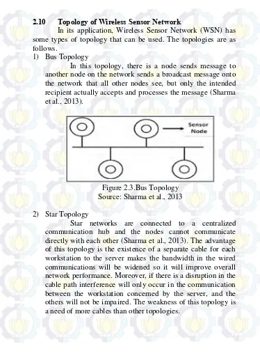
1) Bus Topology
In this topology, there is a node sends message to another node on the network sends a broadcast message onto the network that all other nodes see, but only the intended recipient actually accepts and processes the message (Sharma et al., 2013).
Figure 2.3.Bus Topology Source: Sharma et al., 2013
2) Star Topology
Figure 2.4.Star Topology Source: Sharma et al., 2013
3) Tree Topology
Tree networks are also known as graded network topology. This topology is typically used for interconnection of central with a different hierarchy. The lower hierarchy is depicted on the lower location and the higher hierarchy is depicted on the higher location. As seen in Figure 2.5, the lower hierarchy typically forms star network (Sharma et al., 2013). This topology is suitable used for computer network system.
4) Ring Topology
Ring topology is a topology where every node is connected to two other nodes and forms a circular path like a ring. A failure in node breaks the loop and can take down the entire network (Sharma et al., 2013). In order to anticipate the weakness, FDDI network sends all messages clockwise and counter-clockwise simultaneously.
Figure 2.6.Ring Topology Source: Sharma et al., 2013
5) Mesh Topology
Figure 2.7.Mesh Topology Source: Sharma et al., 2013
2.11 Thermocouple
Thermocouple is the type of temperature sensor used to detect or measure the temperature through two different types of metal conductors which are combined at the ends, giving rise to the effect of thermoelectric. Thermocouple is one type of the most popular temperature sensor and commonly used in a variety of circuits or electrical and electronic equipment related to temperature.
Figure 2.8.Thermocouple
Some of the advantages of thermocouple that make it popular are a rapid response to changes in temperature and also wide range of operational temperatures ranging between -200˚C up to 2000˚C. In addition to fast response and wide temperature range, Thermocouples are also resistant to shock/vibration and easy to use.
2.12 Working Principle of Thermocouple
Thermocouple working principle is quite easy and simple. Basically thermocouple consists of two wires of different kinds of metal conductors and coupled ends. One type of metallic conductors contained in Thermocouple will serve as a reference to a constant temperature (fixed), while the other one as a metallic conductor that detects heat.
Figure 2.9.Thermocouple Source: Kho, 2015
2.13 Processing Analog-Digital Converter
In an industry, physical quantities such as temperature, pressure, fluid flow rate must be controlled. Generally, the controlling system uses PC, PLC, or SCADA. Basically, the physical quantities must be known by a digital system. The physical quantities converted into electrical quantities using sensors. The sensor output is usually in the form of voltage or current (4-20mA default). Then, the voltage/current is converted into a digital scale using ADC (Analog to Digital Converter) component.
1) Analog to Digital Converter (ADC)
ADC is a component that converts analog scale (in this case is the voltage that corresponds to the temperature) and converted into a digital scale. ADC has several important characteristics as follows:
a. Input voltage range b. Bit resolution c. Sampling rate
2) Digital to Analog Converter (DAC)
DAC is the opposite of the ADC, which converts a digital scale into an analog scale (eg, voltage). They have same parameter such as bits of resolution. Normally, sampling rate is not stated in the DAC, since the digital-to-analog conversion takes place very quickly and simply depending on the speed of digital data that is sent to the DAC components.
several types of thermocouple. Those tables contain of several millivolts voltage converted from standard temperature values. These tables are used as references to determine temperature from millivolts manually.
Thermocouple reference tables are based on a reference junction of 0 degree celcius. If the reference junction is not at 0 degree celcius, then a correction factor must be applied. The following are the steps for calculating temperature from voltage (reference junction = 0 degree celcius):
1. Selecting the correct reference table for the thermocouple type in use. For examples: J, K, S, T, etc.
2. Locating the millivolt reading in the body of the table, and then reading from the margins the temperature value.
The thermocouple reference table can only be used directly to determine the temperature if the millivolts voltage is suitable to the value shown in it. For more accurate measurement, an interpolation can be made between two values. The following picture illustrates how the interpolation method is used to arrive at temperature values.
Figure 2.10.Interpolation Method
Based on Figure 2.10, the following is the interpolation formula that can be used for the temperature measurement.
Where:
VM = the measured voltage
VH = the higher voltage read from the table VL = the lower voltage read from the table TM = the calculated temperature
TH = the higher temperature read from the table TL = the lower temperature read from the table
In addition, if the reference junction is greater than 0 degree celcius, it is needed to add the millivolt reading of the reference junction to the measured voltage while calculating temperature from voltage.
2.15 Stowage
Figure 2.11.Incorrect-stuffing of the Container Cargo Source: Meditteranean Shipping Company
Figure 2.12.Correct-stuffing of the Container Cargo Source: Meditteranean Shipping Company
the cargos. This is to keep the temperature equalization in the container as shown in Figure 2.12. If the cargo is not fully loaded, we need to give the additional fillers. The required cargo laying can also be seen in Figure 2.13 below.
29
Experimental research was used as the research design of this study. In order to support the success of this research, it is necessary to choose a research methodology that can be used as a reference in the implementation of the research. This methodology contains some steps performed in the process of problems resolution contained in the research, starting from problem identification to preparing this final report. The stages that will be done to support this study are as follows.
3.1 Study of Literature
The first stage to do is doing study of literature by collecting and learning the supporting sources obtained from the library of Marine Machinery and System Laboratory of Marine Engineering Department; the library of Marine Technology Faculty; the central library of Sepuluh Nopember Institute of Technology; and the internet. These are the sources of this research:
a. Books b. Journals c. Papers d. Articles e. Theses
Meanwhile, the literatures that will be studied are the Wireless Sensor Network (WSN), Reefer Storage, as well as Thermocouple sensor. In addition, researcher will also do a review of similar studies that had been conducted by other researchers.
3.2 Empirical Studies of Wireless Sensor Network (WSN) & Thermocouple
the products in the reefer storage, which in this case are fruits. The data will be used as a reference at a temperature monitoring experiments using both methods, the Wireless Sensor Network and Thermocouple sensors.
Preliminary Analysis and Requirement Specification
Once the data collection was done, empirical studies followed by an analysis of the initial monitoring system that would be used, in this case the Wireless Sensor Network and thermocouple sensors, analysis the specifications of components of both methods, and assessment and design to the layout of the sensor node and variables that would be used. The variables are as follows:
a. Wireless Sensor Network (WSN) Method - Network topology: Star Network - Stowage / Stuffing
b. Thermocouple Sensors Method - Stowage / Stuffing
- Assumption of critical location
3.3 Experiment of Temperature Monitoring System Based on WSN Method
After the installation was done, the sensor nodes were connected to the operator/data collector in the Laboratory of Marine Machinery and Systems wirelessly, using Wi-Fi. In the first experiment, the network was Star Network. It also carried a variation of placement of goods in the reefer storage. The results obtained were temperature and humidity values which would be read in the software that had been provided in realtime.
3.4 Experiment of Temperature Monitoring System Based on Thermocouple Sensors
The first experiment would be followed by a second experiment. That is temperature monitoring experiment using thermocouple sensors. In the second experiment, the laying of thermocouple sensors used based on the data of the sensor nodes’ reading capabilities in the WSN method. The thermocouple sensors were connected to the data logger via cable, before the data were entered into the laptop/PC that had been provided to read the value of the temperature in the reefer storage. Data logger and laptop/PC would be placed close to the reefer storage. In this second experiment, the results obtained in the form of temperature values are read in real time based on variations in the arrangement of items and the assumption of critical locations that had been carried out.
3.5 Data Analysis
3.6 Method Comparison
In this stage, the data analyses of the two methods that had been analyzed earlier were compared. The final result of the method comparison is to know the efficiency and effectiveness of the temperature monitoring using WSN compared to the thermocouple sensors method.
3.7 Conclusion
3.8 The Flow Chart of the Research Methodology
3.9 The Experiment Plot of Wireless Sensor Network Method
Figure 3.2.The Experiment Plot of Wireless Sensor Network Method
3.10 The Experiment Plot of Thermocouple Sensors Method
35
This chapter describes the preparation and process of temperature and humidity data collection through the experiments of temperature monitoring system based on wireless sensor network and thermocouple sensors. Then, the data were processed and analyzed. The analysis results of both methods were compared to obtain more effective method to apply.
4.1 Experimental Apparatus
In order to support the temperature monitoring experiments based on wireless sensor network and thermocouple sensors in reefer storage, the following apparatus were used.
4.1.1 Cold Storage
Cold storage is a tool used for storing goods/products which needs to be stored and cooled down such as vegetables and fruits. Cold storage is the main component utilized for temperature monitoring experiments using both of wireless sensor networks and thermocouple sensors.
As seen on Figure 4.1, a cold storage has these following dimensions.
o Cold Storage : 2400 x 1160 x 2500 (mm) o Freezer : 1230 x 960 x 2300 (mm) o Chiller : 830 x 960 x 2300 (mm)
4.1.2 WSN Apparatus
Wireless Sensor Network experiment has these following equipments.
a. Sensor Nodes: using DT-Sense SHT11 module and IR Temperature Sensor module; has a function to read the data of temperature and humidity in the reefer storage.
b. Coordinator: using Arduino Mega 2560; has a function as the main controller to receive the data from sensor nodes and transmit it to the receriver.
c. XBee Pro (transmitter and receiver): has a function as a wireless communication connected to WSN.
d. Repeater: has a function to strengthen the transmission of the data from the sensors to the receiver.
e. Program GUI: has a function to display the temperature and humidity monitoring data.
f. Admin/Server: has a function as a computer connected to the receiver.
4.1.3 Thermocouple Apparatus
Thermocouple experiment has these following equipments.
a. Thermocouple: using thermocouple type K; has a function to read the data of temperature in the reefer storage.
b. Data logger: using LabJack T7 Pro; has a function as a data reader/logger connected to thermocouple sensors.
4.2 Data Collection Methods
data. The following schemes are the overviews of the implemented data collection methods.
4.2.1 Data Collection Method Based on Thermocouple Sensors At this thermocouple data collection method, the data were taken from the thermocouple readings at several critical points in the reefer storage, and then they were logged in the data logger and displayed through the LJLogM software. As shown in Figure 4.2, the laptop and the data logger were placed close to the reefer storage and connected to thermocouple probes.
Figure 4.2.Thermocouple Scheme
4.2.2 Data Collection Method Based on Wireless Sensor Network
data wirelessly. Then, the data were received by XBee receiver located far from the reefer storage, in this case was in Marine Machinery and Systems Laboratory. During the transmission process, the data were transmitted wirelessly using access point so they were sent to the receiver properly. Afterwards, those received data were displayed in the software installed in a laptop which was connected via a USB cable. Figure 4.3 is the WSN system schematic illustration.
Figure 4.3.Wireless Sensor Network Scheme
4.3 Variables of Data Collection
Table 4.1.Experiments Variables
Variables Experiment Based on Thermocouple on Wireless Sensor Experiment Based Network (WSN)
Control Location of
thermocouple sensors
Location of sensor nodes
Manipulation Stuffing
Assumption of thermocouple probes critical location
Topology Star
Using Coordinator
Stuffing
Response Temperature
Time
Temperature
Humidity
Time
4.4 Experimental Preparation of Thermocouple
Before conducting experiment of temperature monitoring based on thermocouple sensors, there were several things done as a preparation. One of them was arranging the experiment’s equipments and installing and configuring the thermocouple equipments. The following were the preparation details of the experiment.
4.4.1 Apparatus Installation
Figure 4.4.Apparatus Installation of Experiment Using Thermocouple
4.4.2 Installation & Configuration of Data Logger
After assembling and installing the equipments, the data logger supporting softwares of Labjack T7 Pro were installed to the laptop that was used in the experiment. They are Kipling and LJLogM softwares. Then, the installation was continued by configuring the data logger at Kipling by connecting the data logger to the laptop which was used to display the temperature data. The following were the configuration steps that had been implemented.
In the configuration of the Labjack T7 Pro data logger, the first step was starting Kipling software which was installed before. The initial view of Kipling when it first started was shown in Figure 4.5 where the data logger was detected on that software after it was installed on the laptop. The next step was entering the USB menu displayed on the initial view of Kipling by clicking it. It could be done if the laptop and the data logger were connected through the USB cable. It could also be connected via Ethernet and Wifi depending on researcher. The step was shown in Figure 4.6.
Figure 4.6.Connectivity Display of USB Menu at Kipling
Figure 4.7.Devices Information Display at Kipling
The next step was entering the Analog Input menu to set the configuration of thermocouple probes attached to the data logger. Two things that needed to be set here were the type of attached thermocouple probes and the desired error range. As shown in Figure 4.8, there were several analog inputs ranging AIN0 – AIN13 that could be configured. The legible temperatures were voltage values (millivolts) that needed to be converted into the temperature values (oC). The values conversion was done on the LJLogM software.
4.4.3 An Initial Data Collection for Data Logger Calibration After configuring the data logger, the next step was performing the initial trial of LJLogM software which would be used to display the temperature data read by thermocouple sensors. For example, temperature monitoring was performed using two thermocouple sensors conducted at Marine Machinery and System Laboratory where the Air Conditioners were set to 27oC. The initial temperature data that had been read were shown on the display of LJLogM in Figure 4.9.
Figure 4.9.Main Display of LJLogM
While using LJLogM software, data conversion was needed to set where the data read by the thermocouple sensors were voltage data with units of millivolts. Therefore, data conversion was done to change voltage into temperature with units of oC by replacing the name of port’s code. For example, Port 1 which was named AIN0 was changed into AIN0_EF_READ_A and so on. The conversions were shown in Figure 4.9.
4.4.4 Temperature Data Conversion
thermocouple type K were displayed in millivolts (mv) so that the data displayed on LJLogM were small even close to 0 mv. In order to know the readable temperature values, they needed to be converted from voltage into temperature values. According to the Voltage-Temperature conversion method in Chapter 2, researched used the type K thermocouple reference table and calculated the temperature values by applying an interpolation method. The following were several millivolts voltage data sample read by thermocouple for 30 seconds.
Table 4.2.Voltage Data Sample
After recording the data sample, the interpolation method was applied. The following was the example of the calculation of the first data sample (VM = 1.0612 mV).
According to the type K thermocouple reference table, the value of VM is between 1.041 mV and 1.081 mV and the value of TM should be between 26 oC and 27 oC. Based on these, the value of TM could be calculated.
Time (s) Voltage (mV)
2 1.0612 4 1.0595 6 1.0578 8 1.0569 10 1.0560 12 1.0552 14 1.0542 16 1.0535
Time (s) Voltage (mV)
VM = 1.0612 mV VH = 1.081 mV VL = 1.041 mV
TM = calculated TH = 27
o C TL = 26
o C
Thus, the temperature value of thermocouple reading was 26.505 o
C or could be 26.51 oC.
Figure 4.10.Automatic Voltage-Temperature Conversion Code
4.5 Experiment Preparation of Wireless Sensor Network Before conducting experiment of temperature monitoring based on wireless sensor network, there were several things done as a preparation. One of them was preparing the experiment’s apparatus and installing and configuring them. The following were the preparation details of the experiment.
4.5.1 WSN Apparatus Installation
The first thing to do in preparation for experiment using wireless sensor network was assembling and installing the equipments required, such as sensor nodes, a coordinator, a repeater, a receiver module, and a laptop. Figure 4.11 is the apparatus installation of the experiment.
Figure 4.11.WSN Appararus Installation
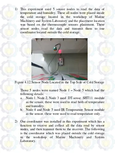
1) This experiment used 5 sensor nodes to read the data of temperature and humidity. These all nodes were placed inside the cold storage located in the workshop of Marine Machinery and System Laboratory and the placement location was based on the thermocouple sensors placement. These sensor nodes read the data and transmit them to one coordinator located outside the cold storage.
Figure 4.12.Sensor Node Located in the Top Side of Cold Storage
Those 5 nodes were named Node 1 – Node 5 which had the following details:
a. Node 1, Node 2, Node 3 used DT-sense SHT11 module as the sensor, these were used to read both of temperature and humidity.
b. Node 4 and Node 5 used IR-Temperature Sensor module as the sensor, these were used to read temperature only.
Figure 4.13.Coordinator of WSN System
3) In order to strengthen the transmission process of the data from the coordinator to the receiver module, it was necessary to install the repeater. This repeater was placed in the other building where the receiver module was located and it was outside Marine Machinery and System Laboratory (100 – 150 meters from the workshop).
Figure 4.14.Repeater
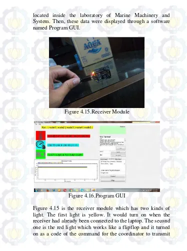
located inside the laboratory of Marine Machinery and System. Then, these data were displayed through a software named Program GUI.
Figure 4.15.Receiver Module
Figure 4.16.Program GUI
the data. Figure 4.16 is Program GUI, a software used to display all the data of temperature, humidity, and also battery that were received by the receiver module. These data would be recorded through this software and saved into the Excel file.
4.6 Apparatus Calibration
Before conducting experiment using both of thermocouple sensors and WSN sensor nodes, the sensors were calibrated. This calibration was performed to identify whether or not the sensors could work properly and can read the temperature appropriately. The reesearcher hereby applied the calibration process to the experimental main apparatus which were the thermocouple type K, DT-sense SHT11 sensor module, IR (infrared) temperature sensor module, and the reefer storage’s thermocouple sensor. By this calibration, the performance of all sensors to read temperature at the same time and condition were compared, as well as their error standard referred to the reefer storage’s thermocouple sensor were found out.
Figure 4.17.Apparatus Calibration
1. All sensors were placed on the same place (under the evaporator) and connected to each system like as Labjack T7 Pro for the thermocouple type K and the coordinator and receiver module of WSN system for the sensor nodes.
2. The softwares of each system were started. In addition, in order to record the temperature data read by the reefer storage’s thermocouple sensor, a digital camera was used. 3. The reefer storage’s evaporator was set on 27 oC with the
differential of 1 oC and the data were recorded during this condition only.
4. After all preparations were done, all the record buttons (of LJLogM software, WSN Program GUI, and digital camera) were clicked at the same time. The softwares were set to record the data every 2 seconds.
The researcher had collected around 90 temperature data for each sensor after taking 3 minutes for recording temperature. Afterwards, the data were processed and analyzed, as well as the deviation standards were calculated. The calibration results can be seen on Chapter 5.
4.7 Stowage Plan and Stuffing
In addition to the pre-experiment preparation in the form of software configuration and data logger and thermocouples calibration, cargo stowaging or stuffing in reefer storage was also planned and performed. It was performed because cargo was the most important part of the experiment.
According to the rules about cargo stowaging and stuffing in reefer storage, in this research, a shelf where several fruit cardboards would be stuffed was designed. The design refered to the dimension of freezer in reefer storage so there would be suitable cargo stuffing results.
plan, there were 14 fruit cardboards which were chosen. All cardboards had the same dimension about 500 mm length, 310 mm width, and 170 mm height. Figure 4.18 (a) and 4.18 (b) were the results of stowage and cargo stuffing plan in reefer storage.
Figure 4.18 (a) Shelf Design, (b) Cargo Stuffing Plan in Reefer Storage
kept to prevent spoilage, so that the quality would be well preserved. According to the Production Guide for Storage of Organic Fruits and Vegetables, the bananas temperature should be kept in the range of 54 – 61 F or 12 – 16 oC. That range was a reference for the experiments that were done. Figure 4.19 was the cargo filling process.
Figure 4.19.Bananas as Cargo in Reefer Storage
4.8 Thermocouple Sensors and Sensor Nodes Placement In order to complete the preparation of the temperature monitoring experiment based on thermocouple sensors, the next step was placing the thermocouple sensors into some points in reefer storage. The placement refered to the critical location of the temperature spread within reefer storage. These critical locations (the researcher determined five locations) were used not only for placing the thermocouple sensors, but also for placing the sensor nodes in the experiment using wireless sensor network so that both of thermocouple sensors and sensor nodes could read the temperature at the same location.
temperature required (related to the pre-cooling time) as seen on Figure 4.20.
Figure 4.20.Thermocouple Placement in the Cargo
For more details, Figure 4.21 and 4.22 were the overview of thermocouple sensors placement within reefer storage. This placement plan was also used to determine the location of WSN sensor nodes.
Figure 4.22.Front View of Sensors Placement
Explanations:
1) Placement of Termocouple Sensors AIN 0 = on the left side of cargo AIN 1 = behind the shelf
AIN 2 = on the right side of cargo AIN 3 = under the shelf
AIN 4 = inserted to a banana outside the cardboard (3rd layer) AIN 5 = inserted to a banana inside the cardboard (2nd layer) AIN 6 = inside the cardboard (2nd layer)
AIN 7 = on the top side of cargo
2) Placement of Sensor Nodes
Node 3 = on the top side of cargo (similar to AIN 7) Node 4 = under the shelf (similar to AIN 3)
Node 5 = inside the cardboard (similar to AIN 6)
Those thermocouples were connected to eight ports of Labjack T7 Pro data logger, namely AIN0 – AIN7, to transmit the temperature data wirely. On the other hand, sensor nodes wirelessly transmitted the data to the coordinator. Furthermore, the experiment based on thermocouple sensors was conducted to read the temperature from every port and so did the experiment based on wireless sensor network.
4.9 Air Flow Rate Measurement
In order to complete the preparation, air flow rate measurement was done. This measurement was aimed to control the air flow rate released by the evaporator. Before doing the measurement, the researcher calculated air flow rate needed by reefer storage. This calculation was based on air flow rate of Daikin 40ft reefer container. The following was the calculation.
Daikin 40ft Reefer Container
Air flow rate = 96.3 m3/min
Volume = 63.25 m3
Reefer Storage Workshop MMS
P x L x T = 1 x 1.25 x 2.3 m
Volume = 2.875 m3
Air flow rate = (2.875 / 63.25) x 96.3 = 4.377 m3/min = 262.62 m3/h = 0.073 m3/s
Marine Machinery and System had been modified by the previous researcher. The modification was done by closing the evaporator by adding a case which has smaller rectangular hole where the cooling air released as seen on Figure 4.23.
Figure 4.23.Modification of the Evaporator
The modification is completed by a plate that can be controlled. It can be used to reduce air flow rate as needed. In order to control air flow rate value 0.073 m3/s, the researcher hereby used anemometer, a tool to measure the air velocity value, as seen on Figure 4.24.
4.10 Experimental Procedure of Temperature Monitoring Based on Thermocouple Sensors
The first temperature monitoring experiment was conducted based on thermocouple sensors. In this experiment, the temperature of thermocouples installed to some points within reefer storage were read by Labjack T7 Pro data logger and the values were displayed on LJLogM software as seen in Figure 4.25.
Figure 4.25.Labjack T7 Pro Installation during Experiment
in the range of 12 – 16 oC). This monitoring was aimed to find out the time needed by banana with normal temperature to be pre-cooled and to determine which type of cargo could be pre-cooled down faster.
The second monitoring was recorded from maximum required temperature (16 oC). It was done at the same time with the monitoring experiment using WSN sensor nodes. Both of them took several hours data monitoring. The data used as the sample of methods comparison. As mentioned on