Software
Engineering
Author
• Microsoft Windows operating systems:
• Processor: 500 MHz Intel Pentium III workstation or equivalent
• Memory: 384 megabytes
• Disk space: 125 megabytes of free disk space • SolarisTM operating system:
• Processor: 450 MHz UltraTM 10 workstation or equivalent • Memory: 384 megabytes
• Disk space: 125 megabytes of free disk space • Linux operating system:
• Processor: 500 MHz Intel Pentium III workstation or equivalent
• Memory: 384 megabytes
• Disk space: 125 megabytes of free disk space Recommended Hardware Configuration
• Microsoft Windows operating systems:
• Processor: 780 MHz Intel Pentium III workstation or equivalent
• Memory: 512 megabytes
• Disk space: 125 megabytes of free disk space • SolarisTM operating system:
• Processor: 500 MHz UltraTM 60 workstation or equivalent • Memory: 512 megabytes
• Disk space: 125 megabytes of free disk space • Linux operating system:
• Processor: 800 MHz Intel Pentium III workstation or equivalent
• Memory: 512 megabytes
• Disk space: 125 megabytes of free disk space Operating System
Below is a list of operating systems that Sun JavaTM Studio Enterprise 8 runs on.
• Solaris 9 and 10 Operating Systems on SPARC Platform • Solaris 10 Operating System on x86 and AMDx64 Platform • Windows XP and Windows 2000
Sun Java Studio Enterprise 8 is provided, but not supported on the following operating systems:
• Linux Software
Sun Java Studio Enteprise 8 runs on J2SE JDK 5.0 (JavaTM 2 JDK, Standard
Edition), which consists of the Java Runtime Environment plus developers tools for compiling, debugging and running application written in the JavaTM
language.
Table of Contents
1 Introduction to Software Engineering... ...7
1.1 Software Engineering- A Layered View... .7
1.1.1 Quality Focus... ...8
1.1.2 Process... .8
1.1.3 Method... ...8
1.1.4 Tools... ...8
1.2 Quality within the Development Effort... .10
1.2.1 What is quality?... ...10
1.2.2 How do we define quality? ... ...10
1.2.3 How do we address the Quality Issues?... ...11
1.3 Software Quality Assurance and Techniques... ...12
1.3.1 Software Quality... ...12
1.3.2 Characteristics of a Well-engineered Software... ....12
1.3.3 Software Quality Assurance Activities... ...13
1.3.4 Formal Technical Reviews... ...13
1.4 The Software Process... ...17
1.4.1 Types of Software Process Models... ...18
1.4.2 Factors that Affect the Choice of Process Model... ...24
1.5 Understanding Systems... ...25
1.6 Understanding People in the Development Effort... ...29
1.6.1 End-users... ....29
1.6.2 Development Team... ...31
1.7 Documentation in the Development Effort... ...32
1.7.1 What is documentation?... ...32
1.7.2 Criteria for Measuring Usability of Documents... ...33
1.7.3 Important of Documents and Manuals... ...34
1.8 Exercises... ...35
1.8.1 Specifying Boundaries... ...35
1.8.2 Practicing the Walkthrough... ...35
1.9 Project Assignment... ...35
2 Object-oriented Software Engineering... ...36
2.1 Review of Object-oriented Concepts... ...36
2.1.1 Abstraction... ...37
2.1.2 Encapsulation... ...38
2.1.3 Modularity... ...38
2.1.4 Hierarchy... ...39
2.2 Object-oriented Process Model... ....43
2.3 Object-oriented Analysis and Design... 44
2.3.1 Object-oriented Analysis... ...44
2.3.2 Object-oriented Design... ...45
2.4 Unified Modeling Language (UML)... ...48
2.4.1 Modeling Activity... ...48
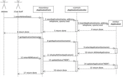
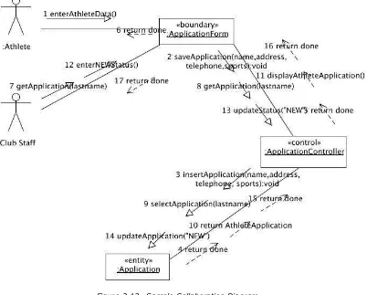
2.4.2 UML Baseline Diagrams... ...51
3 Requirements Engineering... 61
3.1 Requirements Engineering Concepts... ...61
3.2 Requirements Engineering Tasks... ...62
3.2.1 Inception... ...62
3.2.2 Elicitation... ...64
3.2.3 Elaboration... ...67
3.2.4 Negotiation... .67
3.2.6 Validation... ..68
3.2.7 Management... ....69
3.3 Requirements Analysis and Model... ...70
3.3.1 The Requirements Model... ...70
3.3.2 Scenario Modeling... ...71
3.3.3 Requirements Model Validation Checklist...80
3.4 Requirements Specifications... ..82
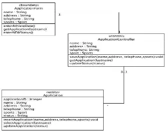
3.4.1 The Analysis Model... ...82
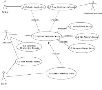
3.4.2 The Use Case Analysis Technique... ...83
3.4.3 Analysis Model Validation Checklist... ...111
3.5 Requirements Traceability Matrix (RTM)... ...112
3.6 Requirements Metrics... ...115
3.7 Exercises... ...118
3.7.1 Creating the Requirements Model ... ...118
3.7.2 Creating Analysis Model... ...118
3.8 Project Assignment... ...118
4 Design Engineering... ...120
4.1 Design Engineering Concepts... ...120
4.1.1 Design Concepts... ...121
4.1.2 The Design Model... ...122
4.2 Software Architecture... ...124
4.2.1 Describing the Package Diagram... .124
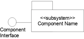
4.2.2 Subsystems and Interfaces... ...125
4.2.3 Developing the Architectural Design... ...130
4.2.4 Software Architecture Validation Checklist... ...137
4.3 Design Patterns... ...138
4.3.1 Model-View-Controller Design Pattern... ...155
4.4 Data Design... ...157
4.4.1 JDBC Design Pattern ... .158
4.4.2 Developing the Data Design Model ... ...163
4.5 Interface Design... ...167
4.5.1 Report Design... ...167
4.5.2 Forms Design... ...170
4.5.3 Screen and Dialog Design ... ...172
4.6 Component-level Design... ...190
4.6.1 Basic Component Design Principles... ...190
4.6.2 Component-level Design Guidelines... ...190
4.6.3 Component Diagram... ...191
4.6.4 Developing the Software Component... ...191
4.7 Deployment-level Design... ...196
4.7.1 Deployment Diagram Notation... ...196
4.7.2 Developing the Deployment Model ...196
4.8 Design Model Validation Checklist... ...197
4.9 Mapping the Design Deliverables to the Requirements Traceability Matrix...198
4.10 Design Metrics... ...199
4.11 Exercises... ...201
4.11.1 Creating the Data Design Model ... ...201
4.11.2 Creating the Interface Design... ...201
4.11.3 Creating the Control Design... ...201
4.12 Project Assignment... ...202
5 Implementation... ...203
5.1 Programming Standards and Procedures... ...203
5.2.1 Using Pseudocodes... ...204
5.2.2 Control Structure Guidelines... ...204
5.2.3 Documentation Guidelines... ...204
5.3 Implementing Packages... .206
5.4 Implementing Controllers... ...208
5.4.1 Review on Abstract Classes and Interfaces...208
5.4.2 Abstract Classes... ...208
5.4.3 Interfaces... ...210
5.4.4 Why do we use Interfaces?... ...210
5.4.5 Interface vs. Abstract Class... ...210
5.4.6 Interface vs. Class... ...211
5.4.7 Creating Interfaces... ...211
5.4.8 Relationship of an Interface to a Class... ...213
5.4.9 Inheritance among Interfaces... ...213
5.5 Implementing Java Database Connectivity (JDBC)... ...217
5.6 Implementing the Graphical User Interface... ...220
5.6.1 AWT GUI Components... ...220
5.6.2 Layout Managers... ...224
5.6.3 Swing GUI Components... ...230
5.7 Controlling the Version of the Software... ...261
5.8 Mapping Implementation Deliverables with the Requirements Traceability Matrix... 266 5.9 Implementation Metrics... ...266
5.10 Exercises... ...267
5.10.1 Defining the Internal Documentation Format... ...267
5.11 Project Assignment... ...267
6 Software Testing... ...268
6.1 Introduction to Software Testing... ...268
6.2 Software Test Case Design Methods... ...269
6.2.1 White-Box Testing Techniques... .269
6.2.2 Black-Box Testing Techniques... ...275
6.3 Testing your Programs... ...278
6.4 Test-driven Development Methodology... ...282
6.4.1 Test-driven Development Steps... ...283
6.4.2 Testing Java Classes with JUnit... ...285
6.5 Testing the System... ...292
6.6 Mapping the Software Testing Deliverable to the RTM...297
6.7 Test Metrics... ..298
6.8 Exercises... ...299
6.8.1 Specifying a Test Case... ...299
6.8.2 Specifying System Test Cases... ...299
6.9 Project Assignment... ...299
7 Introduction to Software Project Management... ...300
7.1 Software Project Management... ...300
7.2 Problem Identification and Definition... .302
7.3 Project Organization... ...305
7.3.1 The Project Team Structure ... ...306
7.3.2 Project Responsibility Chart... ...307
7.4 Project Scheduling... ...309
7.4.1 Project Work Breakdown Structure (WBS)... ...309
7.4.2 Work Breakdown Schedule Format... ...310
7.5 Project Resource Allocation... ...313
7.6 Software Metrics... ...315
7.6.1 Size-oriented Metrics- Lines of Codes (LOC)... .315
7.6.2 Function-Oriented Metrics: Function Points (FP)... ...316
7.6.3 Reconciling LOC and FP Metrics... ...318
7.7 Project Estimations... ...319
7.8 Writing the Project Plan... ...320
7.9 Risk Management... ...321
7.9.1 The Risk Table... ...322
7.9.2 Risk Identification Checklist... ...323
7.10 Software Configuration Management... ...327
7.10.1 Baseline... ...328
7.10.2 Software Configuration Tasks... ...328
7.11 Project Assignment... ...331
8 Software Development Tools... ...332
8.1 Case Tools... ...332
8.2 Compilers, Interpreters and Run-time Support... 332
8.3 Visual Editors... ...332
8.4 Integrated Development Environment (IDE)... ....332
8.5 Configuration Management... ...333
8.6 Database Management Tools... ...333
8.7 Testing Tools... ...333
8.8 Installation Tools... ...333
8.9 Conversion Tools... ...333
8.10 Document Generator... ...333
8.11 Software Project Management... .333
1 Introduction to Software Engineering
When people think about computers, the first thing that comes to their minds are the physical machines- monitor, keyboard, mouse and CPU. However, the software is the one that makes them useful. A computer software includes a set of programs that execute within a computer of any size and architecture, and data that are being processed by the programs and presented to users as hard or soft copies. It is built by software engineers through the employment of a software process that yields high-quality work products that meet the needs of people who will be using the system.
Nowadays, software is a very important technology of our lives because it affects nearly every aspects of it, including government, commerce, and culture. In this chapter, we will be discussing software engineering as a discipline in building quality computer software. A layered view will be used to outline the concepts needed to understand software engineering. Then, an understanding on the people involved in the software development effort will be discussed. It will be followed by the need for documentation and how to organize and document software engineering work products.
1.1 Software Engineering- A Layered View
Software Engineering is a discipline that applies principles of engineering to the development of quality software in a timely and cost-effective manner. It uses an approach that is systematic and methodological to produce quantifiable results. It makes use of measurement and metrics to assess quality, not only of the software but also the software process. They are also used to assess and manage the software development project.
Software Engineering is viewed differently by different practitioners. Pressman suggests to view software engineering as a layered technology1. This view consists of four layers,
namely, quality focus, process, methods and tools. Figure 1.1 illustrates this software engineering view.
1 Pressman, Roger S., Software Engineering, A Practitioner's Approach, Sixth Edition, (Singapore: McGraw-Hill Internal Edition, 2005), p. 53-54
Figure 1.1 Software Engineering- A Layered View
Quality Focus
Process
Methods
1.1.1 Quality Focus
At the very foundation of this layer is a total focus on quality. It is a culture where commitment to continuous improvement on the software development process is fostered. This culture enables the development of more effective approaches to software engineering.
1.1.2 Process
The process integrates the other layers together. It defines a framework that consists of
key process areas that define and enable rational and timely delivery of the computer software. The key process areas are the basis for the software project management. They establish what technical methods are applied, what tools are used, what work products need to be produced, and what milestones are defined. They also include assurance that quality is maintained, and that change is properly controlled and managed.
1.1.3 Method
Methods define a systematic and orderly procedures of building software. They provide
an overall framework within which activities of the software engineer are performed. These activities include a wide array of tasks such as requirements analysis, design, program construction, testing and maintenance.
Methodology is the science of systematic thinking using the methods or procedures used in a particular discipline. There are several software engineering methodologies that are used today. Some of them are briefly enumerated below.
Structured Methodologies:
• Information Engineering
• Software Development Life Cycle/Project Life Cycle
• Rapid Application Development Methodology
Tools provide support to the process and methods. Computer-aided software engineering provides a system of support to the software development project where information created by one tool can be used by another. They may be automated or semi-automated.
a software engineer, specifically, the system model and the software model. The
system model is an inexpensive representation of a complex system that one needs to
study while a software model is a blueprint of the software that needs to be built. Like methodologies, several modeling tools are used to represent systems and software. Some of them are briefly enumerated below.
Structured Approach Modeling Tools:
• Entity-relationship Diagrams
• Data Flow Diagrams
• Structured English or Pseudocodes
• Flow Charts.
Object-oriented Approach Modeling Tools:
1.2 Quality within the Development Effort
As was mentioned in the previous section, quality is the mindset that must influence every software engineer. Focusing on quality in all software engineering activities reduces costs and improves time-to-market by minimizing rework. In order to do this, a software engineer must explicitly define what software quality is, have a set of activities that will ensure that every software engineering work product exhibits high quality, do quality control and assurance activities, and use metrics to develop strategies for improving the software product and process.
1.2.1 What is quality?
Quality is the total characteristic of an entity to satisfy stated and implied needs. These
characteristics or attributes must be measurable so that they can be compared to known standards.
1.2.2 How do we define quality?
Three perspectives are used in understanding quality, specifically, we look at the quality of the product, quality of the process, quality in the context of the business environment2
.
Quality of the Product
Quality of the product would mean different things to different people. It is relative to the person analyzing quality. For end-users, the software has quality if it gives what they want, when they want it, all the time. They also judge it based on ease of use and ease in learning to use it. They normally assess and categorized quality based on external characteristics such as number of failures per type of failure. Failures are categorized as minor, major and catastrophic. For the ones developing and maintaining the software, they take a look at the internal characteristics rather than the external. Examples of which includes errors or faults found during requirements analysis, designing, and coding normally done prior to the shipment of the products to the end-users.
As software engineers, we build models based on how the user's external requirements relate to the developer's internal requirements.
Quality of the Process
There are many tasks that affects the quality of the software. Sometimes, when a task fails, the quality of the software suffers. As software engineers, we value the quality of the software development process. Process guidelines suggests that by improving the software development process, we also improve the quality of the resulting product. Common process guidelines are briefly examined below.
maturity of its development process.
• ISO 9000:2000 for Software. It is a generic standard that applies to any organization that wants to improve the overall quality of the products, systems or services that it provides.
• Software Process Improvement and Capability Determination (SPICE). It is a standard that defines a set of requirements for software process assessment. The intent of the standard is to assist organization in developing an objective evaluation of the efficacy of any defined software process.
Quality in the Context of the Business Environment
In this perspective, quality is viewed in terms of the products and services being provided by the business in which the software is used. Improving the technical quality of the business process adds value to the business, i.e., technical value of the software translates to business value. It is also important to measure the value of the software in terms of business terminologies such as "how many sales orders were processed today?", dollar value on return on investments (ROI) etc. If the software does not add value to the business, why do we need it in the first place?
1.2.3 How do we address the Quality Issues?
We can address quality issues by:
1. Use Quality Standards. Quality standards are sets of principles, procedures, methodologies, and guidelines to bring about quality in the process such as CMMI, ISO 9000:2000 for Software and SPICE.
2. Understand people involved in the development process including end-users and stakeholders. This fosters an environment of collaboration and effective communication.
3. Understand the systematic biases in human nature such as people tend to be risk averse when there is a potential loss, people are unduly optimistic in their plans and forecasts, and people prefer to use intuitive judgment rather than quantitative models.
4. Commit to quality. A mindset focus on quality is needed to discover errors and defects so that they can be addressed immediately.
1.3 Software Quality Assurance and Techniques
Software quality assurance is a subset of software engineering that ensures that all
deliverables and work products are meet, and they comply with user requirements and standards. It is considered as one of the most important activity that is applied throughout the software development process. Its goal is to detect defects before the software is delivered as a final product to the end-users. It encompasses a quality management approach, effective software engineering technology (methods and tools), formal technical reviews, a multi-tiered testing strategy, control of software documentation and the changes made to it, a procedure to assure compliance with software development standards, and measuring and reporting mechanism.
1.3.1 Software Quality
A software has quality if it is fit for use, i.e., it is working properly. In order for it to work properly, it should conform to explicitly stated functional and performance requirements (user's external characteristics), explicitly documented development standards (quality standards), and implicit characteristics (developer's internal characteristics) that are expected of all professionally developed software.
Three important points should be raised from the definition of software quality.
1. Software Requirements are the foundation from which quality is measured. It is necessary to explicitly specify and prioritize them.
2. Standards define a set of development criteria that guide the manner by which the software is engineered.
3. Implicit characteristics must be identified and documented; they influence the way software is developed such as good maintainability.
1.3.2 Characteristics of a Well-engineered Software
To define a well-engineered software, one takes a look at specific characteristics that the software exhibits. Some of them are enumerated below:
• Usability. It is the characteristic of the software that exhibits ease with which the user communicates with the system.
• Portability. It is the capability of the software to execute in different platforms and architecture.
• Reusability. It is the ability of the software to transfer from one system to another.
• Maintainability. It is the ability of the software to evolve and adapt to changes over time. It is characterized by the ease of upgrading and maintaining.
• Dependability. It is the characteristic of the software to be reliable, secure and safe.
1.3.3 Software Quality Assurance Activities
Software Quality Assurance is composed of a variety of activities with the aim of building quality software. It involves two groups of people- development team and SQA team. The SQA team has responsibility over the quality assurance planning, overseeing, records keeping, analyzing and reporting defects and rework. Activities involved are the following:
1. The SQA team prepares the SQA Plan. They do this during the project planning phase. They identify the:
• evaluation to be performed;
• audits and reviews to be performed;
• standards that are applicable;
• procedures for error reporting and tracking;
• documents to be produced; and
• amount of feedback required.
2. The SQA team participates in the development of the project's software process description. The development team selects a software development process and the SQA team checks it if it conform to the organizational policy and quality standards.
3. The SQA team reviews software engineering activities employed by the development teams to check for compliance with the software development process. They monitor and track deviations from the software development process. They document it and ensures that corrections have been made. 4. The SQA team reviews work products to check for compliance with defined
standards. They monitor and track defects or faults found with each work products. They document it and ensure that corrections have been made. 5. The SQA team ensures that deviations in the software activities and work
products are handled based on defined standard operating procedures.
6. The SQA team reports deviations and non-compliance to standards to the senior management or stakeholders.
1.3.4 Formal Technical Reviews
Work products are outputs that are expected as a result of performing tasks in the software process. These results contribute to the development of quality software. Therefore, they should be measurable and checked against requirements and standards. The changes to this work products are significant; they should be monitored and controlled. A technique to check the quality of the work products is the formal technical review. Formal Technical Reviews (FTR) are performed at various points of the software development process. It serves to discover errors and defects that can be removed before software is shipped to the end-users. Specifically, its goals are:
1. to uncover errors in function, logic or implementation for any representation of the software;
3. to ensure that the software has been represented according to defined standards;
4. to achieve software that is developed in a uniform manner; and 5. to make projects more manageable.
A general guideline of conducting formal technical reviews is listed below.
• Review the work product NOT the developer of the work product. The goal of the review is to discover errors and defect to improve the quality of the software. The tone of the review should be loose but constructive.
• Plan for the agenda and stick to it. Reviews should not last more than two hours.
• Minimize debate and rebuttal. It is inevitable that issues arise and people may not agree with its impact. Remind everybody that it is not time to resolve these issues rather have them documented, and set another meeting for their resolutions.
• Point out problem areas but do not try to solve them. Mention and clarify problem areas. However, it is not time for problem-solving session. It should be done and schedule for another meeting.
• Write down notes. It is a good practice to write down notes so that wording and priorities can be assessed by other reviewers. It should aid in clarifying defects and actions to be done.
• Keep the number of participants to a minimum and insist on preparing for the review. Writing down comments and remarks by the reviewers is a good meeting. It also helps the reviewers stay focus on the review.
• De-brief the review. It checks the effectiveness of the review process.
Two formal technical reviews of work products used in industry are the Fagan's
Inspection Method and Walkthroughs.
Fagan's Inspection Method
It was introduced by Fagan in 1976 at IBM. Originally, it was used to check codes of programs. However, it can be extended to include other work products such as technical documents, model elements, data and code design etc. It is managed by a moderator who as responsibility of overseeing the review. It would required a team of inspectors assigned to play roles that checks the work product against a prepared list of concerns. It is more formal that a walkthrough. It follows certain procedural rules that each member should adhere to. Those rules are listed as follows:
planning and systems development.
• All classes of defects in documentation and work product are inspected not merely logic, specifications or function errors.
• Inspection are carried out by colleagues at all levels of seniority except the big boss.
• Inspections are carried out in a prescribed list of activities.
• Inspection meetings are limited to two hours.
• Inspections are led by a trained moderator.
• inspectors are assigned specific roles to increase effectiveness. Checklists of questionnaires to be asked by the inspectors are used to define the task to stimulate increased defect finding. Materials are inspected at a particular rate which has been found to give maximum error-finding ability.
• Statistics on types of errors are key, and used for reports which are analyzed in a manner similar to financial analysis.
Conducting inspections require a lot of activities. They are categorized as follows:
• Planning. A moderator is tasked to prepare a plan for the inspection. He decides who will be the inspectors, the roles that they have to play, when and where they have to play the roles, and distributes the necessary documentation accordingly.
• Giving of the overview. A 30-minute presentation of the project for the inspectors are given. It can be omitted if everybody is familiar with the overall project.
• Preparing. Each inspector is given 1 to 2 hours alone to inspect the work product. He will perform the role that was assigned to him based on the documentation provided by the moderator. He will try to discover defects in the work product. He is discouraged to fix the defects or criticize the developer of the work product.
• Holding the meeting. The participants of the meeting are the inspectors, moderator and the developer of the work product. The developer of the work product is present to explain the work product, and answer questions that inspectors ask. No discussion about whether the defect is real or not is allowed. A defect list is produced by the moderator.
• Reworking of the work product. The defect list is assigned to a person for repair. Normally, this is the developer of the work product.
• Following up the rework. The moderator ensures that the defects on the work products are addressed and reworked. These are later on inspected by other inspections.
Walkthrough
A walkthrough is less formal than the inspection. Here, the work product and corresponding documentation are given to a review team, normally around 3 people, where comments of their correctness are elicited. Unlike the inspection where one has a moderator, the developer of the work product, moderates the walkthrough. A scribe is also present to produce an action list. An action list is a list of actions that must be done in order to improve the quality of the work product which includes the rework for the defects, resolution of issues etc.
Some guidelines must be followed in order to have a successful walkthrough. They are listed below:
• No manager should be present.
• Emphasize that the walkthrough is for error detection only and not error correction.
• Keep vested interest group apart.
• No counting or sandbagging.
• Criticize the product; not the person.
• Always document the action list.
Conducting a walkthrough, similar with inspection, would require many activities. They are categorized as follows:
• Pre-walkthrough Activities
• The developer of the work product schedules the walkthrough preferably, a day or two in advance.
• He distributes the necessary materials of the work product to the reviewers.
• He specifically asks each reviewer to bring to the walkthrough two positive comments and one negative comment about the work product.
• Walkthrough Proper
• The developer of the work product gives a brief presentation of the work product. This may be omitted if the reviewers are familiar with the work product or project.
• He solicit comments from the reviewers. Sometimes, issues arise and presented but they should not find resolutions during the walkthrough. Issues are listed down in the action list.
• An action list is produced at the end of the walkthrough.
• Post-walkthrough Activities
• The developer of the work product receives the action list.
• He is asked to submit a status report on the action taken to resolve the errors or discrepancies listed in the action list.
1.4 The Software Process
The software process provides a strategy that a software development team employs in
order to build quality software. It is chosen based on the nature of the project and application, methods and tools to be used, and the management and work products that are required. Pressman provides a graphical representation of the software process. According to him, it provides the framework from which a comprehensive plan for software development can be established. It consists of framework activities, tasks sets and umbrella activities.3
Framework of Activities
These are activities that are performed by the people involved in the development process applicable to any software project regardless of project size, composition of the development team, and complexity of the problem. They are also known as phases of the software development process.
Task Sets
Each of the activities in the process framework defines a set of tasks. These tasks would have milestones, deliverables or work products and software quality assurance (SQA) points. They are modified and adjusted to the specific characteristic of the software project, and the requirements of the software.
Umbrella Activities
These are activities that supports the framework of activities as the software development project progresses such as software project management, change 3 Pressman, Software Engineering A Practitioner's Approach, p. 54-55
management, requirements management, risk management, formal technical reviews etc.
1.4.1 Types of Software Process Models
There are many types of software process models that suggest how to build software. Common process models are discussed within this section.
Linear Sequential Model
The Linear Sequential Model is also known as the waterfall model or the classic life
cycle. This is the first model ever formalized, and other process models are based on
this approach to development. It suggests a systematic and sequential approach to the development of the software. It begins by analyzing the system, progressing to the analysis of the software, design, coding, testing and maintenance. It insists that a phase can not begin unless the previous phase is finished. Figure 1.3 shows this type of software process model.
The advantages of this model are:
• It is the first process model ever formulated.
• It provides a basis for other software process models.
The disadvantages of this model are:
• Real software projects rarely follow a strict sequential flow. In fact, it is very difficult to decide when one phase ends and the other begins.
Figure 1.3 Linear Sequential Model Requirements
Engineering
Design Engineering
Coding
Testing
• End-user involvement only occurs at the beginning (requirements engineering) and at the end (operations and maintenance). It does not address the fact the requirements may change during the software development project.
• End-users sometimes have difficulty stating all of their requirements. Thus, it delays the development of the software.
Prototyping Model
To aid in the understanding of end-user requirements, prototypes are built. Prototypes
are partially developed software that enable end-users and developers examine aspects of the proposed system and decide if it is included in the final software product. This approach is best suited for the following situations:
• A customer defines a set of general objectives for the software but does not identify detailed input, processing, or output requirements.
• The developer may be unsure of the efficiency of an algorithm, the adaptability of a technology, or the form that human-computer interaction should take. Figure 1.4 shows this process model.
The advantage of this process model is:
• The end-users have an active part in defining the human-computer interaction requirements of the system. They get the actual "feel" of the software.
The disadvantages of this process model are:
• Customers may mistakenly accept the prototype as a working version of the software. Software quality is compromised because other software requirements are not considered such as maintainability.
• Developers tent to make implementation compromises in order to have a working prototype without thinking of future expansion and maintenance.
Rapid Application Development (RAD) Model
This process is a linear sequential software development process that emphasizes an extremely short development cycle. It is achieved through a modular-based construction approach. It is best used for software projects where requirements are well-understood, project scope is properly constrained, and big budget with resources are available. Everybody is expected to be committed to a rapid approach to development.
In this process model, the software project is defined based on functional decomposition of the software. Functional partitions are assigned to different teams, and are developed in parallel. Figure 1.5 shows this process model.
The advantage of this model is:
• A fully functional system is created in a short span of time.
The disadvantages of this model are:
• For large but scalable projects, this process requires a sufficient number of developers to have the right number of development teams.
• Developers and customers must be committed to the rapid-fire of activities necessary to develop the software in a short amount of time.
• It is not a good process model for systems that cannot be modularized.
• It is not a good process model for systems that require high performance.
• It is not a good process model for systems that make use of new technology or
high degree of interoperability with existing computer programs such as legacy systems.
Evolutionary Process Models
This process model recognizes that software evolves over a period of time. It enables the development of an increasingly more complicated version of the software. The approach is iterative in nature. Specific evolutionary process models are Incremental Model,
Spiral Model, and Component-based Assembly Model.
Incremental Model
This process model combines the elements of a linear sequential model with the iterative philosophy of prototyping. Linear sequences are defined where each sequence produces an increment of the software. Unlike prototyping, the increment is an operational product. Figure 1.6 shows this process model.
Spiral Model
It was originally proposed by Boehm. It is an evolutionary software process model that couples the iterative nature of prototyping with the controlled and systematic aspects of linear sequential model. It provides potential rapid development of incremental versions of the software. An important feature of this model is that it has risk analysis as one of its framework of activities. Therefore, it requires risk assessment expertise. Figure 1.7 shows an example of a spiral model.
Figure 1.7 Spiral Model
Risk Analysis Planning
Communication
Analysis & Design
Coding & Release Evaluation
A B C D
A. Initial Software Project
B. Maintenance of New Software C. Enhancement of Software
Component-based Assembly Model
It is similar to Spiral Process Model. However, it makes use of object technologies where the emphasis of the development is on the creation of classes which encapsulates both data and the methods used to manipulate the data. Reusability is one of the quality characteristics that are always checked during the development of the software. Figure 1.8 shows the Component-based Assembly Model.
Figure 1.8 Component-based Assembly Model Risk
D. Development of another interrelated system
Concurrent Development Model
The Concurrent Development Model is also known as concurrent engineering. It makes use of state charts to represents the concurrent relationship among tasks associated within a framework of activities. It is represented schematically by a series of major technical tasks, and associated states. The user's need, management decisions and review results drive the over-all progression of the development. Figure 1.9 shows the concurrent development model.
Formal Methods
The Formal Methods is a software engineering approach which encompasses a set of activities that lead to mathematical specification of the software. It provides a mechanism for removing many of the problems that are difficult to overcome using other software engineering paradigm. It serves as a means to verify, discover and correct errors that might otherwise be undetected.
1.4.2 Factors that Affect the Choice of Process Model
• Type of the Project
• Methods and Tools to be Used
• Requirements of the Stakeholders
• Common Sense and Judgment
Figure 1.9 Concurrent Development Model
1.5 Understanding Systems
The software project that needs to be developed revolves around systems. Systems
consists of a group of entities or components, interacting together to form specific interrelationships, organized by means of structure, and working together to achieve a common goal. Understanding systems provides a context for any project through the definition of the boundaries of the projects. It asks the question, "What is included in the project? What is not?" In defining the system boundaries, a software engineer discovers the following:
• entities or group of entities that are related and organized in some way within the system, either they provide input, do activities or receive output;
• activities or actions that must be performed by the entities or group of entities in order to achieve the purpose of the system;
• a list of inputs; and
• a list of outputs.
As an example, Figure 1.10 shows the system boundaries of the case study. It shows elements of this system through the use of the context diagram.
Entities that are involved in this system are the applicant, club staff and coach. They are represented as rectangular boxes. They are related with one another by performing certain activities within this system. The major activities that are performed are the submission of the application forms, scheduling of mock try-outs and the assignment of the applicant to a squad. They are represented by a circle in the middle that defines the functionality of maintaining club membership information. To perform these actions, a list of inputs are necessary, specifically, application forms and the schedule of the mock try-outs. They are represented by an arrow with the name of the data being passed. The arrow head indicates the flow of the data. The results that are expected from this system are the membership reports and importantly, the squad listings. Again, they are represented by an arrow with the name of the data being passed. The arrow head
indicates the flow of the data. The goal of this system is to handle club membership application.
General Principles of Systems
Some general principles of systems are discussed below. This would help the software engineer study the system where the software project revolves.
• The more specialized a system, the less it is able to adapt to different circumstances. Changes would have a great impact on the development of such systems. One should be carefully that there is no dramatic changes in the environment or requirements when the software is being developed. Stakeholders and developers should be aware of the risks and costs of the changes during the development of the software.
• The larger the system is, the more resources must be devoted to its everyday maintenance. As an example, the cost of maintaining a mainframe is very expensive compared to maintaining several personal computers.
• Systems are always part of larger systems, and they can always be partitioned into smaller systems. This is the most important principle that a software engineer must understand. Because systems are composed of smaller subsystem and vice versa, software systems can be developed in a modular way. It is important to determine the boundaries of the systems and their interactions so that the impact of their development is minimal and can be managed and controlled.
Components of Automated Systems
There are two types of systems, namely, man-made systems and automated systems. Man-made systems are also considered manual systems. They are not perfect. They will always have areas for correctness and improvements. These areas for correctness and improvements can be addressed by automated systems.
Automated systems are examples of systems. It consists of components that supports the operation of a domain-specific system. In general, it consists of the following:
1. Computer Hardware. This component is the physical device.
2. Computer Software. This component is the program that executes within the machine.
3. People. This component is responsible for the use of the computer hardware and software. They provide the data as input, and they interpret the output (information) for day-to-day decisions.
4. Procedures. This component is the policies and procedures that govern the operation of the automated system.
5. Data and Information. This component provides the input (data) and output (information).
Figure 1.11 shows the relationship of the first five components.
Let's take a look of an application domain-specific illustration of an automated system. Figure 1.12 shows the automated system of the club membership application processing.
Figure 1.11 Components of An Automated System
1
Figure 1.12 Club Membership Application Computer System
1.6 Understanding People in the Development
Effort
To help in the fostering of a quality mindset in the development of the software, one should understand the people involved in the software development process, particularly, their interest regarding the system and the software that needs to be developed. In this section, there are two major groups that are involved in the software development effort, specifically, end-users and development team.
1.6.1 End-users
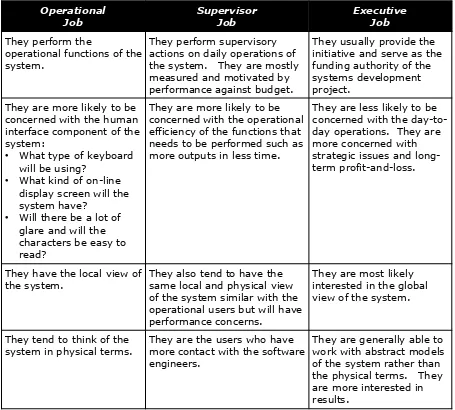
End-users are the people who will be using the end-product. Much of the requirements will be coming from this group. They can be grouped into two according to their involvement within the system organization and development, namely, those who are directly involved and those who are indirectly involved.
Those who are directly involved
Operational the system. They are mostly measured and motivated by
They are more likely to be concerned with the human
They are more likely to be concerned with the operational efficiency of the functions that needs to be performed such as more outputs in less time.
They are less likely to be concerned with the day-to-day operations. They are more concerned with strategic issues and long-term profit-and-loss.
They have the local view of the system.
They also tend to have the same local and physical view of the system similar with the operational users but will have performance concerns.
They are most likely interested in the global view of the system.
They tend to think of the system in physical terms.
They are the users who have more contact with the software engineers.
They are generally able to work with abstract models of the system rather than the physical terms. They are more interested in results.
Table 1: Job Category
General Guidelines with End-Users
• The higher the level of the manager, the less he or she is likely to care about computer technology. It would be best to ask him or her over-all results and performance the system can provide. They are good candidates for interview regarding the report layouts and code design.
• The goals and priorities of management may be in conflict with those of the supervisory and operational users. This can be seen based on their different levels of concerns. As software engineer, try to discover areas of commonality. More on this on Chapter 3- Requirements Engineering.
Those who are indirectly involved
Mostly, these group includes the auditors, standard bearers, and quality assurance group. The general objective of this group is to ensure that the system is developed in accordance with various standard set such as:
• Accounting standards developed by the organization's accounting operations or firm.
• Standards developed by other departments within the organization or by the customer or user who will inherit the system
• Various standards imposed by the government regulatory agencies.
Some possible problem that may be encountered with this group. As software engineers, keep an eye on them and address them accordingly.
• They don't get involved in the project until the very end, particularly, the quality assurance group. It is important that they be involved in every activity that would require their expertise and opinion.
• They provide the necessary notation and format of documentation. They may be needed in the definition of the presentation and documentation of the system.
• They are more interested in substance rather than form.
1.6.2 Development Team
The development team is responsible in building the software that will support a domain-specific system. It may consists of the following: systems analyst, systems designer, programmer and testers.
System Analyst
His responsibility is understanding the system. Within this system, he identifies customer wants, and documents and prioritizes requirements. This involves breaking down the system to determine specific requirements which will be the basis for the design of the software.
System Designer
His job is to transform a technology free architectural design that will provide the framework within which the programmers can work. Usually, the system analyst and designer are the same person but it must be emphasized that the functions require different focus and skill.
Programmers
Based on the system design, the programmers write the codes of the software using a particular programming language.
Testers
1.7 Documentation in the Development Effort
1.7.1 What is documentation?
It is a set of documents or informational products to describe a computer system. Each document is designed to perform a particular function such as:
• REFERENCE, examples are technical or functional specifications
• INSTRUCTIONAL, examples are tutorials, demonstrations, prototypes etc.
• MOTIVATIONAL, examples are brochures, demonstrations, prototypes.
There are several types of documentation and informational work products. Some of them are listed below:
• System Features and Functions
• User and Management Summaries
• Users Manual
• Systems Administration Manuals
• Video
• Multimedia
• Tutorials
• Demonstrations
• Reference Guide
• Quick Reference Guide
• Technical References
• System Maintenance Files
• System Test Models
• Conversion Procedures
• Operations/Operators Manual
• On-line help
• Wall Charts
• Keyboard Layouts or Templates
• Newsletters
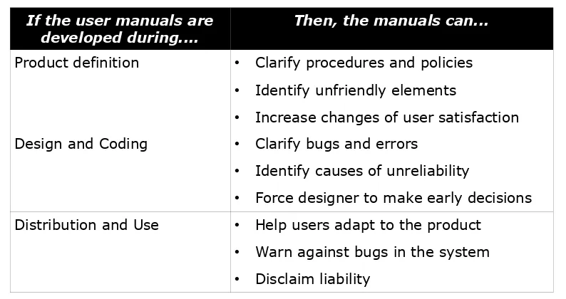
If the user manuals are developed during....
Then, the manuals can...
Product definition • Clarify procedures and policies
• Identify unfriendly elements
• Increase changes of user satisfaction
Design and Coding • Clarify bugs and errors
• Identify causes of unreliability
• Force designer to make early decisions Distribution and Use • Help users adapt to the product
• Warn against bugs in the system
• Disclaim liability
Table 2 Documentation Significance
There are two main purpose of documentation. Specifically, they:
• provide a reasonably permanent statement of a system's structure or behavior through reference manuals, user guides and systems architecture documents.
• serve as transitory documents that are part of the infrastructure involved in running real projects such as scenarios, internal design documentation, meeting reports, bugs etc.
1.7.2 Criteria for Measuring Usability of Documents
A useful document furthers the understanding of the system's desired and actual behavior and structure. It serves to communicate the system's architectural versions. It provides a description of details that cannot be directly inferred from the software itself or from executable work products. Some criteria for measuring usability of documents are listed below:
1. Availability. Users should know that the documents exists. It must be present when and where needed.
2. Suitability. It should be aligned to users tasks and interests. It should be accurate and complete. Related documents must be located in one manual or book.
3. Accessibility. It should fit in an ordinary 8.5in x 11in paper for ease of handling, storage, and retrieval. It should be easy to find the information that users want. Each item of documentation should have a unique name for referencing and cross-referencing, a purpose or objective, and target audience (who will be using the document). Referrals to other manuals and books should be avoided.
1.7.3 Important of Documents and Manuals
Documents and manuals are important because:
• They save cost. With good manuals, one needs less personnel to train the users, support on-going operations, and maintain the system.
• They serve as sales and marketing tools. Good manuals differentiate their products- a slick manual means a slick product- especially, for off-the-shelf software products.
• They serve as tangible deliverables. Management and users know little about computer jargons, programs and procedures, but they can hold and see a user manual.
• They serve as contractual obligations.
• They serve as security blankets. In case people leave, manuals and technical documents serve as written backup.
• They serve as testing and implementation aids. It is important to include the following items as part of the user's manual- system test scripts and models, clerical and automated procedures, hands-on training for new personnel and design aid.
1.8 Exercises
1.8.1 Specifying Boundaries
1. Model the system boundary of the Coach Information System. Use Figure 1.10 as your guide.
2. Model the system boundary of the Squad and Team Maintenance System. Use Figure 1.10 as your guide.
1.8.2 Practicing the Walkthrough
1. Review the system boundary model of the Coach Information System by performing a walkthrough. Prepare an action list.
2. Review the system boundary model of the Squad & Team Maintenance System by performing a walkthrough. Prepare an action list.
1.9 Project Assignment
The objective of the project assignment is to reinforce the knowledge and skills gained in Chapter 1. Particularly, they are:
1. Defining the System Boundaries 2. Creating the System Boundary Model 3. Performing Walkthrough
WORK PRODUCTS:
2 Object-oriented Software Engineering
Object-oriented Software Engineering is the use of object technologies in building
software. Object technology is a set of principles that guide the construction of the software using object-oriented approach. It encompasses all framework of activities including analysis, design and testing, and the choice of methodologies, programming languages, tools, databases and applications to engineer a software.
In this chapter, we lay the foundation for understanding object-orientation by presenting an explanation of its fundamental concepts such as objects and classes, abstraction, encapsulation, modularity and hierarchy. We also present a general object-oriented process model that follows a component-based assembly. We also introduce object-oriented analysis and design activities, list down some methodologies, and expected work products. Finally, we will discuss the Unified Modeling Language (UML) and the modeling activity.
2.1 Review of Object-oriented Concepts
At the very heart of object-orientation, we have the objects. Objects are representations of entities which can be physical (such as club membership application form and athletes), conceptual (squad assignment) or software (linked list). It allows software engineers to represent real world objects in software design. More technically, it is defined as something that represents a real world object which has a well-defined boundary and identity that encapsulates state and behavior.
Attributes and relationships of an object define its state. It is one of the possible conditions by which an object exists, and it normally changes overtime. In software, the values stored within the attributes and the links of the object with other objects define this state. Operations, methods and state machines, on the other hand, define its
behavior. It determines how an object acts and reacts to message requests from other
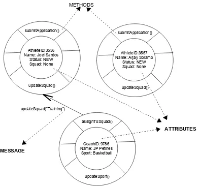
objects. It is important that each object should be uniquely identified within the system even if they have the same values in the attributes and behavior. Figure 2.1 depicts examples of objects with their state and behavior that may exists in the case study, Ang Bulilit Liga.
Three objects are present- 2 athletes and 1 coach. In this picture, they are illustrated as circles where attributes are found in the inner circle surrounded by methods. Objects are uniquely identified by their Ids such as in the case of the two athletes, Joel and Arjay. Notice that attributes are enclosed by methods. This suggests that only the object can change the values of their own attributes. The changes in the values of the attributes can be triggered by a request, called a message, by another object. In the picture, the coach (JP) assigns an athlete (Joel) to a squad by executing his method assignToSquad (). This method sends a request message, updateSquad("Training"), to the athlete (Joel) to update his squad attribute.
A class is a description of a set of objects that share the same attributes, relationships,
methods, operations and semantics. It is an abstraction that focuses on the relevant characteristics of all objects while ignoring other characteristics. Objects are instances of classes. In our example, Joel and Arjay are instances of the class athletes, while JP
Four basic principles that are generally associated with object-orientation are abstraction, encapsulation, modularity and hierarchy. This concepts are interrelated and supports one another.
2.1.1 Abstraction
Abstraction is defined as the essential characteristics of an entity that distinguishes it
from all other kinds of entities1
. It is a kind of representation that includes only the things that are important or interesting from a particular point of view. It is domain and perspective dependent, i.e., what is important in one context may not necessarily be important in another. It allows us to manage the complexity of the system by concentrating only on those characteristics that are essential or important in the system, and ignoring or de-emphasizing the characteristics that are not. Objects are represented by those features that are deemed relevant to the current purpose, and hides those features that are not.
Examples of abstraction within the case study are:
1 Object-oriented Analysis and Design using the UML, Student's Manual , (Cupertino, CA: Rational software Corporation, 2000), p. 2-15
Figure 2.1 Club Membership Application Object Examples
• An applicant submits a club membership application to the club staff.
• A club staff schedules an applicant for a mock try-outs.
• A coach assigns an athlete to a squad.
• A squad can be a training squad or a competing squad.
• Teams are formed from a squad.
2.1.2 Encapsulation
Encapsulation is also known as information hiding. It localizes features of an entity
into a single blackbox abstraction, and hides the implementation of these features behind an interface. It allows other objects to interact with one another is such a way that they don't need to know how the implementation fulfills the interface. This is achieved through the object's message interface. This interface is a set of pre-defined operations used so that other objects can communicate with it. It ensures that data within the attributes of the object are accessible through an object's operation. No other object can directly access these attributes, and change their values.
Consider the interaction among objects in Figure 2.1 where a coach (JP) assigns an athlete (Joel) to a squad. updateSquad() is the message interface that changes the value of the squad attribute of the athlete (Joel). Notice, that the change will only occur when the coach (JP) executes assignToSquad() which triggers a request to updateSquad ("Training") of the squad attribute (Joel's). The coach (JP) does not need to know how the athlete (Joel) updates the squad but is assured that the method is executed.
Encapsulation reduces the "ripple effect of changes" on codes, where a change in one object's implementation will cause another change in another object's implementation and so on. With encapsulation, one can change the implementation without changing the other object's implementation as long as the interface is unchanged. Thus, encapsulation offers two kinds of protection to objects: protection against corruption of internal state and protection against code change when another object's implementation changes.
2.1.3 Modularity
Modularity is the physical and logical decomposition of large and complex things into
small and manageable components. These components can be independently developed as long as their interactions are well-understood. The concepts of packages, subsystems and components in object-orientation support modularity. They will be explained further in the succeeding sections of this chapter.
Modularity, like abstraction, is another way of managing complexity. Because it breaks something that is large and complex into smaller manageable components, it makes it easier for a software engineer to manage and develop the software by managing and developing these smaller components. Then, iteratively integrate them.
2.1.4 Hierarchy
Hierarchy can be any ranking of ordering of abstraction into a tree-like structure. There
are different kinds of hierarchy, and they are listed below.
• Aggregation
• Class
• Containment
• Inheritance
• Partition
• Specialization
• Type
Figure 2.3 shows an example of the Squad Hierarchy.
Figure 2.2 Ang Bulilit Liga Subsystems
Ang Bulilit Liga
Squad and Team System
Club Membership Maintenance
System
Coach Information Maintenance
System
Squad and Team Maintenance
System
Figure 2.3 Squad Hierarchy
Squad
Training Squad
Generalization is a form of association wherein one class shares the structure and/or behavior of one or more classes. It defines a hierarchy of abstractions in which a subclass inherits from one or more superclass. It is an is a kind of relationship. In Figure 2.3, the Squad class is the superclass of the Training Squad and Competing Squad
classes.
Inheritance is a mechanism by which more specific elements incorporate the structure
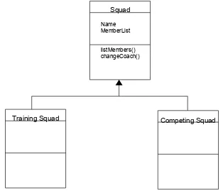
and behavior of more general elements. A subclass inherits attributes, operations and relationships from a superclass. Figure 2.3 is elaborated in Figure 2.4, all attributes and methods of the Squad superclass are inherited by the subclasses Training Squad and
Competing Squad.
Polymorphism is the ability to hide many different implementation behind a single interface. It allows the same message to be handled differently by different objects. Consider the classes defined in Figure 2.5 which will be used to discuss polymorphism1.
A superclass Person is modeled with two subclasses Student and Employee.
Figure 2.4 Elaborated Squad Hierarchy
Squad
Name MemberList
listMembers() changeCoach()
Training Squad Competing Squad
Figure 2.5 Polymorphism Sample
Person
In Java, consider the following code to implement the classes.
Notice that both Student and Employee have different implementation of the getName()
method. Consider the following Java Main Method where ref is a reference to a class
Person. The first time that the ref.getName() is invoked, it will execute the getName()
method of Student since ref references a studentObject. The second time that the
ref.getName() is invoked, it will execute the getName() method of Employee since ref references a employeeObject.
public static main( String[] args ) {
Person ref;
Student studentObject = new Student(); Employee employeeObject = new Employee();
ref = studentObject; //Person reference points to a // Student object
String temp = ref.getName(); //getName of Student //class is called
System.out.println( temp );
ref = employeeObject; //Person reference points to an // Employee object
String temp = ref.getName(); //getName of Employee //class is called
System.out.println( temp );
Aggregation is a special kind of association between objects. It models a whole-part relationship between an aggregate (whole) and its parts. Figure 2.6 shows an example of an aggregation. Here, the team is composed of athletes.
Figure 2.6 Team Aggregation