SIMULATION OF POWER ELECTRICAL CIRCUITS OF
AUTOMOTIVE
by
Emilian Ceuca and Serban Lungu
Abstract. In this paper, a procedure for identifying the transfer functions of Park’s dq-axis model of a synchronous generator has been developed for analyzing automotive charging systems. This application note focuses on one particular aspect of charging system design: alternator/regulator performance. This voltage regulated power system must operate satisfactorily under extreme transient conditions.
Two of these transients, a load-dump condition (heavy electrical load switching with a disconnected battery), and an engine rapid crankshaft speed-up, are examined.
It will be shown that the parameters of this model can be easily identified from standstill time-domain data. The validity of the theoretical model has been verified by comparing time-time-domain simulations with measurements taken from the direct-drive synchronous generator.
Key Words. Transfer functions, synchronous generator, automotive
1. Introduction
Recent advances in power electronics applied to alternators. Constant speed operation has not been the choice of alternators designers, but rather a necessity brought about by the fixed relationship between the speed of the DC generators and the fixed utility grid frequency. The two main advantages of variable speed operation over constant speed operation are additional energy capture at partial load and potential reduction of fatigue loads.
Fatigue load reduction is the most important and underestimated advantage of variable rotational speed operation. Obviously, it requires high bandwidth control. The bandwidth of the active blade pitch system is, in general, too small to achieve fatigue load reduction.
equivalent circuit parameters rather than on transfer functions. A few papers address methods of identifying the parameters from time-domain data. In both cases, the parameter estimation process generally consists of two parts. First, the time constants are extracted by applying a curve-fitting procedure to measured data. Next, the equivalent circuit parameters are determined by solving a set of nonlinear equations through numerical optimization. The weakness of this approach is that the order of the model must be known before the parameters can be determined and that numerical optimization is a process fraught with numerical difficulties [8].
In this paper, a procedure is developed [5] for identifying the transfer functions of Park’s dq-axis model of a synchronous generator from time-domain standstill step-response data. The contribution of this paper is that Park’s dq-axis model equations are rewritten such that a model structure arises that can be easily translated into a simulation scheme. The order of the rational transfer functions is not fixed, but is determined by the data. The combination of identifying rational transfer functions and a high signal-to-noise ratio resulting from a standstill test offers the possibility to analytically determine the model parameters. That is, the identification procedure does not require good initial parameter values.
2. Modeling the alternator (when operating like Synchronous Generator)
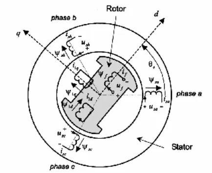
The aim of this section is to set up a theoretical model of alternator operating like synchronous generator suited for both time-domain simulation and model based control design. In essence, there are two aspects that need to be modeled: the mechanical and the electromagnetic part. The mechanical part can be modeled using the techniques outlined in Molenaar [9]. In the present paper, we will restrict to the dynamic modeling of the electromagnetic part. From a modeling point of view, all synchronous generators have similar representations. They differ only with respect to some model parameters. Because the round-rotor synchronous generator is a special case of the salient-pole rotor synchronous generator, we will treat only the latter for an arbitrary number of pole-pairs p. Figure 1 depicts a salient-rotor synchronous generator with only one pole-pair ( p=1). The machine has the usual three stator windings, each 120 (electrical) degrees apart. The stator windings are star connected. The rotor has one accessible circuit, the field or excitation winding, and two sets of inaccessible circuits, called damper windings. Damper windings are real or fictitious windings that can be used to represent, for example, the damping effects of eddy currents in the machine. In Fig. 1, one damper winding is located along the direct-axis, and one along the quadrature-axis (represented by Ρ1d and Ρ1q in Fig. 1). When the DC
According to Park [10,11], the voltage equations of an ideal synchronous generator, linear magnetic circuit and stator windings are sinusoidal distributed along the stator circumference in the dq reference frame are given by (using generator sign convention for the stator circuits):
d s d e q d
dt
d
i
R
u
=
−
−
ω
ψ
−
ψ
q d e q s q
dt
d
i
R
u
=
−
+
ω
ψ
−
ψ
(1)f f f f
dt
d
i
R
u
=
−
−
ψ
−
with ud the direct-axis voltage [V], Rs the stator-winding resistance [Σ], id the
direct-axis current [A], Τe =d2e / dt the electrical angular frequency [rad/s], Ρq the quadrature
-axis winding flux [Vs], t time [s], Ρd the direct-axis winding flux [Vs], uq the
quadrature-axis voltage [V], iq the quadrature-axis current [A], uf the field -winding
voltage [V], Rf the field-winding resistance[Σ], if the field-winding current [A], and Ρf
the field-winding flux [Vs].
A few observations can be made. The most important one is that (1) are coupled via the fluxes. In addition, they depend on the electrical angular frequency Τe, thereby
introducing non-linearity’s. The fluxes are given by
)
(
)
(
)
(
)
(
)
(
s
L
dos
I
ds
L
dfos
I
fs
d
=
+
ψ
)
(
)
(
)
(
s
L
qs
I
qs
q
=
ψ
(2))
(
)
(
)
(
)
(
)
(
s
L
fdos
I
ds
L
fos
I
fs
f
=
+
ψ
with s the Laplace operator, Ρd,q,f the Laplace transformed fluxes, Id,q,f the Laplace transformed currents, and Ldo (s), Lfdo(s)= Ldfo(s), Lq(s), Lfo(s)
Fig. 1 Schematic representation of an elementary three-phase, synchronous generator
For a finite number of damper windings, the aforementioned transfer functions can be expressed as a ratio of polynomials in s [12]. Furthermore, in his original paper R. H. Park used the non-power invariant transformation to transform the stator quantities onto the dq reference frame that is fixed to the rotor. In the above derivation, we have used the power-invariant version in order to ensure that in both reference frames the same power expressions are obtained. In addition, he used motor sign convention for the stator circuits.
The dynamic behavior of an ideal synchronous generator is thus fully described by the sets (1) and (2) expressed in the dq reference frame. For time-domain simulation purposes, it is convenient to rewrite the first set of equations in the following form
dt
i
R
u
d s d e qd
(
ω
ψ
)
ψ
=
−
∫
+
+
ψ
q=
−
∫
(
u
q+
R
si
q+
−
eψ
d)
dt
(3)dt
i
R
u
f f ff
=
∫
(
−
)
ψ
=
f d fo fdo fdo do f dI
I
s
L
s
L
s
L
s
L
)
(
)
(
)
(
)
(
ψ
ψ
(4)It can be easily shown that the inverse transformation is given by
−
−
−
=
f d fdo fo do do fdo fdo fo f ds
L
s
L
s
L
s
L
s
L
s
L
s
L
I
I
ψ
ψ
)
(
)
(
)
(
)
(
)
(
)
(
)
(
2 (5)
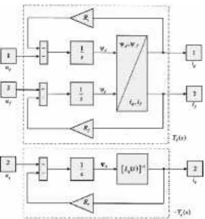
[image:5.595.206.406.289.502.2]From those equations we can conclude blocks diagrams
Fig. 2 Block diagram of an ideal synchronous machine
In addition, it can be shown that the denominators of Ldo(s),Lfdo(s), Ldfo(s), Lfo(s) are
3. Identification of parameters
Synchronous machine identification and parameter determination can be performed either during normal operation (on-line), or during specially designed identification experiments (off-line). A disadvantage is that it is not possible to manipulate the input signals arbitrarily in order to obtain the best identification results. This implies that the influence of the operating conditions on the (accuracy of) identified parameters has to be careful analyzed.
Off-line identification experiments have been used for decades to identify electrical machine parameters. Two concepts are commonly used: running machine or standstill. Standstill tests are very attractive from a practical viewpoint: if it is permissible to take the machine out of operation, because driving the machine often creates serious complications of the measurement set-up [13].
Furthermore, the measured signals will have good signal-to-noise ratios due to the absence of disturbance signals (electromagnetic Interference). All standstill tests reported in literature are variations on the same concept, they mainly differ in the kind of excitation signal applied (i.e., step, ramp, sinusoidal, or random excitation).
The standstill test concept is preferred because there is no interaction between the direct and the quadrature axis. Using this observation, it can be concluded that the parameter identification for both axes may be carried out separately. In practice, zero generator speed can be enforced by mechanically locking the rotor during the experiments.
Before selecting the most appropriate standstill test, we will first highlight the most important aspects of both the quadrature-axis and the direct-axis identification.
A. Quadrature-Axis Identification. The dynamic behavior of the quadrature-axis of an ideal synchronous generator is fully described by the transfer function Yq(s) in Fig.
2. From the block diagram it directly follows that
)
(
1
)
(
)
(
)
(
s
sL
R
s
U
s
I
s
Y
q s q
q q
+
=
−
=
(6)For the identification of Yq(s), knowledge of the quadrature-axis voltage uq(t) and
current iq(t) is thus both necessary and sufficient. It will be shown below that these
quantities can be easily derived from three measurable variables, the stator voltages of the b and c phase (ub(t) and uc(t) ), and the stator current ic(t).
An appropriate rotor position for quadrature-axis identification is the one when the field winding axis is parallel to the a-phase winding (i.e.,2e =0, see Fig. 1). In addition,
if in this position the stator b – c terminals are excited while the a-terminal remains open ia(t)=0, it follows that ib(t) = - ic(t) . Furthermore, it can be concluded from
Substituting the above results in the equations for the transformed stator voltages and currents
s dq
dq
T
u
u
0=
0s dq
dq
T
i
i
0=
0where
[
]
Tq d
dq
u
u
u
u
0=
0[
]
Tc b a
s
u
u
u
u
=
[
]
Tq d
dq
i
i
i
i
0=
0and T0dq the Park’s power-invariant transformation matrix,
+ − + − = ) 3 2 sin( ) 3 2 sin( ) sin( ) 3 2 cos( ) 3 2 cos( ) cos( 2 1 2 1 2 1 3 2 0
π
θ
π
θ
θ
π
θ
π
θ
θ
e e e e e e dq T gives
2
(
)
2
1
b c
q
u
u
u
=
−
u
d=
0
i
q=
2
i
ci
d=
0
(7)Finally, the q-axis parameters (Lq(s) and Rs are deduced
algebraically from the transfer function Yq(s).
B Direct-Axis Identification. The dynamic behavior of the direct-axis of an ideal synchronous generator is fully described by the transfer function matrix Yd(s) between
ud, uf and id , if in Fig. 2. In this case, an appropriate rotor position is the one when
the field winding axis is perpendicular to the a-phase winding (i.e.,2e =π/2, see Fig. 1).
it follows that:
) (
2 2 1
b c
d u u
u = −
u
q=
0
i
d=
2
i
ci
q=
0
(8)In principle, the elements of (5) Lfo(s),Lfdo(s), and Ldo(s) can be identified using data
acquired from two independent measurements, namely one with excitation of the quadrature-axis voltage while the field winding is left open and one when the field winding is short-circuited [13]. Combining the resulting transfer functions gives the required 2x2 transfer function matrix.
One way to overcome this problem is to identify the transfer function between the fluxes Ρd , Ρf and the currents id , if and assuming that both Rs and Rf are known.
Recall that the stator winding resistance is known from the quadrature-axis identification. One possible way to determine the field winding resistance is by a stepwise excitation of uf and measuring if .
Neither the direct-axis winding flux Ρd, or the field winding flux Ρf, however, can be
measured in practice. Conversely, these variables can be generated by integration of (3) with the ud , uf , id , and if acting as input. Analogous to the quadrature-axis
identification, the latter variables can be deduced from the three measurable variables ub, uc, and ic.
C Testing and Selection of Excitation Signal. It is straightforward to understand that the character of the input signal that is applied during the experiment highly determines the amount of relevant information that is present in the data. For example, applying a constant input signal u(t )=c to the generator will not result in an output signal that contains any information on the dynamics of the system. Observe that in this case only static behavior can be uniquely determined. Consequently, in order to extract sufficient information from measured data concerning the dynamics, conditions have to be imposed on the character of the input signal.
Generally step-response testing may be more practical for obtaining parameters for installed synchronous machines. Summarizing, based on both the excitation requirements and the practical demands, a step-response test seems the most appropriate test among the standstill tests for the identification and parameter determination of alternator.
4. Measurement Set-Up
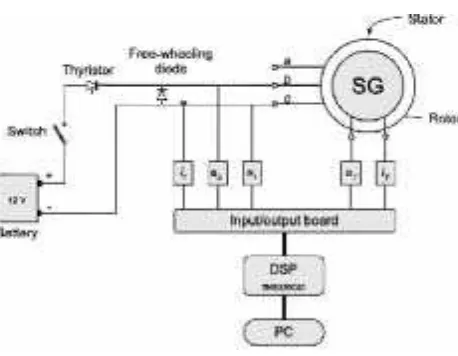
Fig. 3 Charghing system in automotive
Fig. 4 Scheme of the measurement set-up of the modified step-response test as used for the identification of the machine
parameters
[image:9.595.190.419.298.476.2]Depending on the measurement type, a combination of the following signals is measured: ic , (stator current), ubc (stator voltage), uf (field winding voltage), and if
(field winding current).
The data-acquisition system consists of three main parts, an input-output I/O board, a digital signal processor board from with a TMS320C40 processor from Texas Instruments®, and a personal computer (PC) connected to the processor board. The automated data-acquisition process is started by switching on the (mechanical) switch and subsequently triggering the thyristor.
A. Data-Acquisition and Identification Procedure. The modified step-response test consists of three successive measurements:
1. Q-measurement. Rotor positioned such that the quadrature axis is excited;
2. D-measurement. Rotor positioned such that the direct axis is excited, while the field winding is short-circuited;
3. Rf -measurement. Stepwise excitation of uf and measu-ring if.
B. Parameter Estimation Procedure. System identify-cation or parameter estimation deals with constructing mathematical models of dynamical systems from experimental data. The parameter estimation procedure picks out the best model within the chosen model structure according to the measured input and output sequences and some identification criterion. A common and general method of estimating the parameters in system identification is the prediction error method [16]. In this method, the parameters of the model are chosen so that the difference between the model’s (predicted) output and the measured output is minimized.
The developed identification procedure consists of next steps:
• Model structure and order selection. It is trivial that a bad model structure cannot offer a good, low order model, regardless the amount and quality of the available data. The measured input-output data is imported into graphical user interface. If the resulting model, however, produces an unsatisfactory simulation error and/or if the input is correlated with the residual, the model is rejected and another model structure (or order) is selected. This continues until the model produces a satisfactory simulation error and results in zero cross-covariance between residual and past inputs. In that case it can be concluded that a consistent model estimate has been obtained;
confronted with as much information about the process as practical. Here, the outputs of the identified model are compared to the measured ones on a data set that was not used for the fit (called validation data set).
C. Model Validation. As mentioned above, the outputs of the identified model are compared to the measured ones from a validation data set to (in)validate the model. The percentage of the output variations that is reproduced by the model is chosen as measure of the goodness of fit.
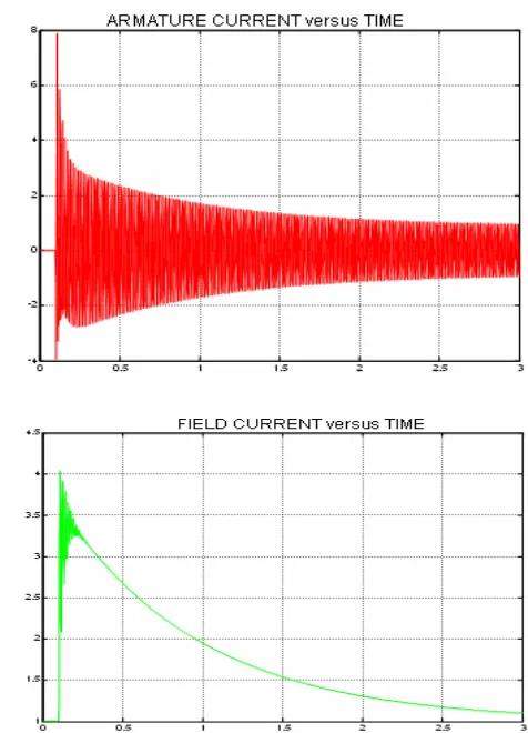
D. Results. The q-axis transfer function Yq(s) of the elec-tromagnetic part of the
generator has been identified. A third order model turns out to be sufficient. The q-axis parameters are derived from Yq(s) as outlined above.
The structure of the symmetric d-axis transfer function matrix and both inputs id and if
,the percentage of the variations in the fluxes Ρd, Ρf that is reproduced by the fourth
order model is larger than 99.5%.
Fig. 5 Scheme of the measurement set-up of the modified step-response test as used for the identification of the machine
parameters
Observe that if is not equal to zero because the short-circuit is not perfect due to the
slip-rings In addition, the quality of the model is also checked by examining the cross correlation function between inputs and output residuals. In both cases, an almost zero cross-covariance exists.
5. Conclusions
• A theoretical model of the electromagnetic part
of a synchronous generator has been proposed. It has been shown that the parameters of this model can be easily identified following the developed procedure. The required input-output data is obtained from the modified step-response test.
• This test is the most favorable standstill test considering equipment costs and weight, measurement time, and complexity.
The validity of the theoretical model has been verified by comparing time-domain simulations with measurements.
Combination of the aforementioned results leads to the conclusion that it is possible to identify an accurate model of the electromagnetic part of the generator on the basis of modified step-response data.
Future Work. The validated model will be used to develop a new , robust frequency converter controller for high dynamic performance in automotive industry.
References
[1] Boije, E. S., Balda, J. C., Harley, R. G., and Beck, R. C., 1990, Time-Domain Identification of Synchronous Machine Parameters From Standstill Tests’’, IEEE Trans. on Energy Conversion, 164–175.
[2] Keyhani, A., Tsai, H., and Leksan, T., 1994, ‘‘Maximum Likelihood Estimation of Synchronous Machine Parameters From Standstill Time Response Data , IEEE Trans. on Energy Conversion, 98–114.
[3] Le, L. X., and Wilson, W. J., 1998, ‘‘Synchronous Machine Parameter Identification: ATime-Domain Approach”, IEEE Trans. on Energy Conversion, 241– 248.
[4] Saunders, R. M., 1991, ‘‘Synchronous-Machine Standstill Frequency-Response Test Data Analysis,’’ IEEE Trans. on Energy Conversion, 564–571.
[5] Touhami, O., Guesbaoui, H., and Iung, C., 1994, ‘‘Synchronous Machine Parameter Identification by a Multitime Scale Technique”, IEEE Trans. Ind. Appl, 1600–1608.
[6] Tumageanian, A., and Keyhani, A., 1995, ‘‘Identifica-tion of Synchronous Machine Linear Parameters From Standstill Step Voltage Input Data’’, IEEE Trans. on Energy Conversion, 232–240.
[7] IEEE Standard 115-1995; IEEE Guide: Test Procedures for Synchronous Machines Part I—Acceptance and Performance Testing and Part II–Test Procedures and Parameter Determination for Dynamic Analysis 1996, Institute of Electrical and Electronics Engineers, Inc. New York, NY.
[8] Henschel, S., and Dommel, H. W., 1999, ‘‘Noniterative Synchronous Machine Parameter Identification from Frequency Response Tests’’, IEEE Trans. On Power Systems, pp. 553–560.
[10] Park, R. H., 1929, ‘‘Two-Reaction Theory of Synchronous Machines, Generalized Method of Analysis, Part I’’, AIEE Transactions, 716–730.
[11] Park, R. H., 1933, ‘‘Two-Reaction Theory of Synchronous Machines, Generalized Method of Analysis, Part II,’’ AIEE Transactions, 352–355.
[12] Kundur, P., 1994, Power System Stability and Control, McGraw-Hill, Inc.
[13] Minnich, S. H., 1986, ‘‘Small Signals, Large Signals, and Saturation in Generator Models’’, IEEE Transactions on Energy Conversion, 95–103.
[16] Ljung, L., 1995, System Identification-Theory for the User, Prentice-Hall, Englewood Cliffs, NJ.
[17] System Identification Toolbox User’s Guide, 1995, MathWorks, Inc.
Authors:
Emilian Ceuca, University “1 Decembrie 1918” Alba Iulia, N. Iorga 11-13, Romania, [email protected]