DETERMINATION OF UAS TRAJECTORY
IN A KNOWN ENVIRONMENT FROM FPV VIDEO
Julien Li-Chee-Ming, Costas Armenakis
Geomatics Engineering, GeoICT Lab
Department of Earth and Space Science and Engineering
Lassonde School of Engineering, York University
Toronto, Ontario, M3J 1P3 Canada
{julienli}, {armenc} @yorku.ca
Commission I, ICWG I/Vb
KEY WORDS: Unmanned Aerial Systems, First Person View video, Georeferencing, Map-based Navigation
ABSTRACT:
This paper presents a novel self-localization method. The algorithm automatically establishes correspondence between the FPV video streamed from a UAS flying in a structured urban environment and its 3D model. The resulting camera pose provides a precise navigation solution in the densely crowded environment. Initially, Vertical Line Features are extracted from a streamed FPV video frame, as the camera is kept approximately leveled through a gimbal system. The features are then matched with Vertical Line Features extracted from a synthetic image of the 3D model. A space resection is performed to provide the EOPs for this frame. The features are tracked in the next frame, followed by an incremental triangulation. The main contribution of this paper lies in automating this process as an FPV video sequence typically consists of thousands of frames. Accuracies of the position and orientation parameters of the video camera and the validation checks of the estimated parameters are presented. Future work includes testing the method in real-time to determine latencies and reliability, and multi-directional field of view of the FPV video camera.
1. INTRODUCTION
First-person view (FPV) unmanned aerial systems (UAS) are equipped with a small forward-looking video camera and a transmitter to downlink the video signal wirelessly in real-time to a ground station monitor or virtual reality goggles. FPV gives the pilot a perspective from the „cockpit‟ of the UAS. This allows the radio-controlled aircraft to be flown more intuitively than by visual line-of-sight and beyond the pilot‟s visual range –where the aircraft‟s separation from the pilot is limited only by the range of the remote control and video transmitter.
FPV systems are commonly used solely as a visual aid in remotely piloting the aircraft. This paper presents a method to further extend the application of this system by estimating the position and orientation of the UAS from the FPV video in near real time as it travels through a known 3D environment. The obtained quantitative information on position and orientation of the aerial platform will support the UAS operator in navigation and path planning. If an autopilot is available it may also be used to improve the position and orientation of the navigation solution. Precise navigation is required in urban missions, where the possibility of crashing is high, as UASs fly at low altitudes among buildings and need to avoid obstacles and perform sharp maneuvers. This is especially useful in GPS-denied environments, or in dense-multipath environments such as urban canyons.
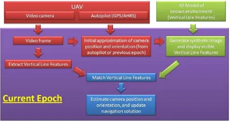
The developed self-localization process requires a metric 3D model of the environment. The main steps, as illustrated in Figure 1, are:
1. Extract Vertical Line Features from the online video frame.
2. Match these features with those in the 3D model of the environment, according to certain criteria. 3. Update the camera pose, or exterior orientation
parameters (EOPs), as a function of the matched feature locations in the map.
Figure 1. The self-localization process
The main contribution of this paper lies in automating the localization process because an FPV video sequence typically consists of thousands of frames. It is based on a simple, efficient, and robust feature extraction approach developed to find correspondence between video frames and the 3D model of the environment.
2. DATA COLLECTION
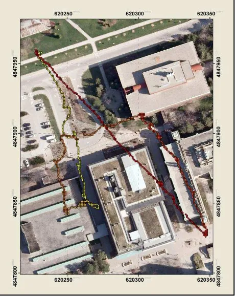
To demonstrate the approach, video captured from the onboard camera of an Aeryon Scout quad-copter (Figure 2; Aeryon, 2013) was used (GeoICT and Elder Laboratories, 2012). The Scout flew over York University, up to approximately 60 metres above the ground, while the gyro-stabilized camera focused on buildings, walkways, and trees. The UAS‟s flight path is depicted in Figure 4, where the UAS was observing
York University‟s Lassonde Building. The EOPs automatically estimated from the video were used to augment the UAS‟s autopilot solution, derived from the onboard single frequency GPS receiver and MEMS-IMU.
Figure 2. The Aeryon Scout UAS in York University (GEOICT and Elder Laboratory, 2012)
The 3D virtual building model of York University‟s Keele
campus (Armenakis and Sohn, 2009) was used as the known environment. The model consists of photorealistic reconstructions of buildings, trees, and terrain, generated from building footprint vector data, DSM with 0.75m ground spacing, corresponding orthophotos at 0.15 m spatial resolution and terrestrial images. The 3D building model was further refined with airborne lidar data having a point density of 1.9 points per square metre (Corral-Soto et al, 2012). This 3D CAD model serves two purposes in our proposed approach. Firstly, it provides the necessary level of detail of linear features (vertical and horizontal lines) for feature matching, where initial tests indicate that at least 5 linear features are required to be available per video frame. Secondly, it provides control points to achieve photogrammetrically sub-meter accuracies of the positional elements of the exterior orientation. The results of this paper demonstrate that sub-meter accuracies in the UAS' XYZ components are achieved at 40 m AGL using a single image (640 x 480 pixels). The geometric accuracy of the model used is in the order of 10-20 cm. Ongoing testing, through UAS simulation and experimental flights, are resolving the minimum level-of-detail and accuracy required for the model to achieve sub-meter positional accuracy at various altitudes, and with various cameras.
Figure 3 shows the virtual campus in Google Earth, along with the UAS flight path. One frame was captured from the video to demonstrate the self-localization methodology presented in this work. The camera symbol signifies the GPS position collected by the UAS‟ autopilot when this frame was captured.
The strategy to facilitate finding correspondence between the
3D building model and the UAS‟ video imagery is to generate,
in real time, a synthetic image of the model captured from a
vantage point and perspective approximate to the UAS‟ current
pose, then extract features from the current video frame and match them with the model features that are visible in the synthetic image.
Figure 3. 3D York University Campus Model
Figure 4. UAS flight path around the Lassonde Building
3. THE SYNTHETIC IMAGE OF THE 3D MODEL
To obtain the synthetic image of the 3D model, a simulator, such as Gazebo, or Google SketchUp in this case, may be used.
The 3D model was loaded in the simulator‟s environment. At
each video frame, an approximate position is used to set the
simulator‟s camera position. In this case, the autopilot‟s GPS position was available. Alternatively, a prediction from the
previous epoch‟s camera position may be used. The autopilot‟s
attitude solution could not be used to approximate the
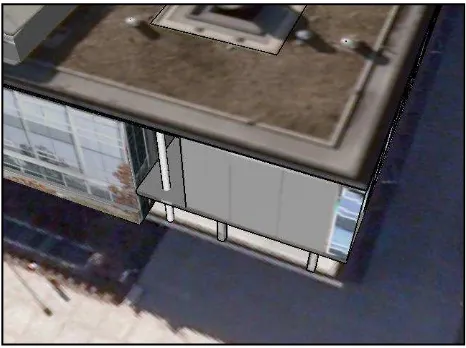
vector. The Target, a point in space that the camera is pointing to, is used to define the pitch and yaw of the camera, the Up vector, the direction that the top of the camera is facing, is used to define the roll of the camera. The Target was set to the average of the 50 closest vertices belonging to the building model, and the Up vector was parallel to the vertical axis (signifying a zero degree roll angle). Alternatively, vanishing points extracted from the video image could be used to approximate the orientation of the simulated camera with respect to the building; however, this option is more computationally demanding. Finally, in order for the synthetic image and video image to have similar scales, the video camera was calibrated, and the obtained values were used to define the interior orientation parameters of the simulated camera. Figure 5 shows the video frame for a selected epoch and Figure 6 shows the synthetic image.
Figure 5. Sample video frame (640 x 480 pixels)
4. RELATED WORK
Comparing the two images in Figures 5 and 6, the texture of the building model had little correlation with the UAS‟s imagery because of changes in illumination and weather conditions, and the presence of shadows. Further, the colours of buildings change with time, for example when roofs are repaired or walls are painted. This is especially true for the Lassonde building, as the vegetation on the roof changes seasonally. However, the shape of the building remains constant in time and is more suitable for matching. Thus, this work focuses towards matching geometric features (points, lines, polygons, etc.), as opposed to intensity-based features such as SIFT (Lowe, 1999) and SURF (Bay et al., 2008). This is convenient as 3D models generally provide a database of georeferenced vertices (points), edges (lines), and faces (polygons).
Matching two sets of points using ICP (Besl et al., 1992) is commonly used in real-time and can handle outliers, occlusions, appearances and disappearances. However, the method requires an accurate initial approximation. Extracting feature points with a corner detector, such as Harris corners complexity and run-time of the system.
Matching silhouettes has been proposed (Latecki et al., 2000), but are limited as they ignore internal contours and are difficult to extract from real images. More promising approaches match edges based on, for example, the Hausdorff distance (Huttenlocker et al., 1993; Valtkamp and Hagedoorn, 1999) or Distance Transform (Gavrilla et al., 1999). A drawback for this application is that the method does not return correspondence. Geometric hashing (Lamdan et al. 1990) performs matching based on spatial configurations of keypoints without explicitly solving for correspondence and the method is robust for missing points and occlusion. A hashing data structure is built prior to matching, which makes finding correspondence time efficient. However, the data structure can become very large, depending on the size of the data and the class of transformation (Belongie et al., 2002).
Figure 6. Sample synthetic image
Line matching approaches divide into algorithms that match individual line segments, and algorithms that match groups of line segments. Matching single lines is based on geometric properties, such as orientation, length, and extent of overlap. Matching groups of lines takes away the ambiguity involved by providing more geometric information. Graph-matching is a common approach, as graphs capture relationships such as left of and right of, and topological connectedness (Baillard et al., 1999).
5. FEATURE EXTRACTION
The feature chosen to correspond between the model and the image consists of two corners joined by an image line. This feature was chosen because it commonly appears in structured environments and it is simple and computationally efficient to extract from an image. A method was developed to reliably identify corresponding features.
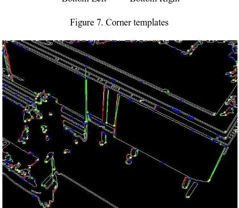
points correspond to Top Right Corners, and yellow points correspond to Bottom Right Corners.
Top Left Top Right
Bottom Left Bottom Right
Figure 7. Corner templates
Figure 8. The extracted corners and Vertical Line Features from the edge image of the video frame
Many „false corners‟ were detected in the video image. These points often correspond to objects surrounding the building and are not present in the 3D model, such as trees and signs. To narrow the search space for correspondence, detected corners are rejected if they do not meet a condition that forms a Vertical Line Feature. That is, all of the following conditions should be met:
1. A Left/Right Vertical Line Feature is a continuous line of pixels that connect a Top Left/Right Corner to a Bottom Left/Right Corner.
2. Given the camera is kept level by the gimbal system, the slope of the line should be within a tolerable
range of the vertical defined by the image‟s vertical
axes.
3. The Top Left/Right Corner should be higher in the image than the Bottom Left/Right Corner.
All the combinations of Top Left/Right Corners and Bottom Left/Right Corners are sequentially tested against the various conditions. If a Top Left/Right Corner and Bottom Left/Right Corner do not meet a condition, the pair of points is discarded and the next combination of points is tested. Tests are
performed in increasing order according to computational complexity to increase efficiency.
Correspondence is based solely on Left and Right Vertical lines. Top and Bottom Horizontal Lines Features are extracted in a similar fashion only if an insufficient number of corresponding Vertical Line Features is found, as this will increase the processing time.
Figure 9. Left (red) and Right (green) Vertical Line Features overlayed on the synthetic image
Using the same method, the Vertical Line Features were extracted from the 3D model offline. The model‟s vertices were classified according to corner type, and vertical edges were classified as either Left or Right Vertical Lines. Figure 9 shows the Left Vertical Line Features (red) and Right Vertical Line Features (green) that are visible in the synthetic image.
6. FEATURE MATCHING
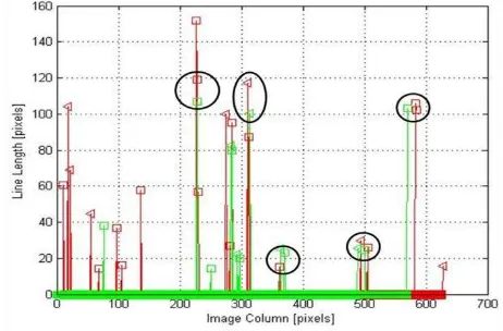
Given that the scales of the synthetic image and the video frame are similar, the horizontal spacing between the vertical lines should be similar as well. Thus, a horizontal shift should align both sets of vertical lines. This shift is evident in Figure 10, where for each Vertical Line Feature the column value of
the line‟s centroid is plotted against the length of the same line.
The red series signifies the lines extracted from the video frame, and the green series corresponds to the lines from the synthetic image. The triangles symbolize Left Vertical Line Features, and squares symbolize Right Vertical Line Features.
The maximum value of the cross correlation of the red (video) series and green (model) series provides the numerical value of the horizontal shift. The Vertical Line Features from the synthetic image are shifted and matched with the Vertical Line Features from the video frame based on proximity and line length. Figure 11 shows the lines from the video images with the shifted lines from the synthetic image. Potential Vertical Line Feature matches are circled.
7. TRAJECTORY DETERMINATION
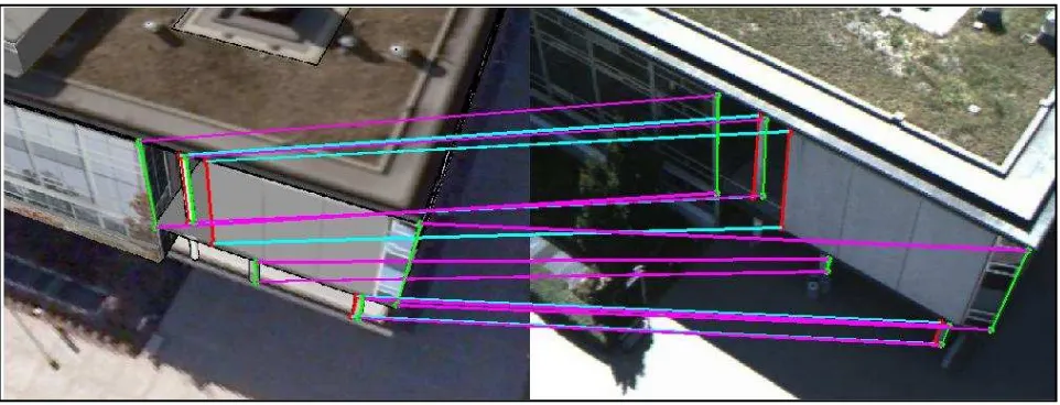
estimate the geometry robustly. Figure 13 shows the resulting correspondence between the video frame and synthetic image. A space resection is then performed to determine the video camera EOPs.
Figure 10. Horizontal shift between the Vertical Line Feature
Figure 11. Corresponding Vertical Line Features between the video frame (red) and synthetic image (green) are circled
To identify 3D control points in the synthetic image, each georeferenced vertex of the 3D model is assigned an RGB colour. By extracting the colour of a vertex in the synthetic image, the 3D georeferenced coordinates are obtained. As an initial approximation for the camera‟s position and orientation was available, space resection via collinearity was performed for both the video frame and synthetic image, the results are provided in Table 1.
Feature matching via correlation between the video image and synthetic image was shown to be successful with the orientation angles differing by as much as 11 degrees. Further testing is required to determine the maximum allowable pose separation between the video camera and the simulated camera.
The resection yielded sub-metre positional accuracy, which is an improvement from the 2 to 3 metre accuracy obtainable by a WAAS-enabled GPS receiver, especially in the vertical component. The features for which correspondence was found are then tracked in the next video frame through the KLT
feature tracking followed by an incremental triangulation for each successive key frame.
Figure 12. Colour-coded Ground Control Points visible in the synthetic image
8. CONCLUSIONS AND FUTURE WORK
Future work will involve further development of the algorithm to determine correspondence between the video image and the model without the need of an initial approximate position from the GPS sensor. The camera pose can be estimated through space resection via DLT as opposed to the nonlinear collinearity equations where initial values for position and orientation are required.. The DLT method is proposed for the incremental photogrammetric triangulation for computational efficiency due to the time critical operations. Testing of the
method‟s robustness against occlusions, and testing in real-time to determine latencies and reliability will be also conducted.
ACKNOWLEDGEMENTS
Special thanks are given to the members of York University‟s
GeoICT Lab who contributed to generating the York University 3D Virtual Campus Model, namely, Damir Gumerov, Yoonseok Jwa, Brian Kim, and Yu Gao.
We also thank Professor James Elder‟s Human & Computer Vision Lab in York University‟s Centre for Vision Research for providing the UAS video data.
REFERENCES
Armenakis C., Sohn, G., 2009. iCampus: 3D modeling of York University Campus, CD-ROM Proceedings 2009 Annual Conference of the American Society for Photogrammetry and Remote Sensing, Baltimore, MA, USA.
Aeryon, 2013. Aeryon Scout Brochure. Available online at: http://www.aeryon.com/products/avs/aeryon-scout.html
Bay, H., Ess, A., Tuytelaars, T., Van Gool, L., 2008. SURF: Speeded Up Robust Features, Computer Vision and Image Understanding (CVIU), Vol. 110, No. 3, pp. 346-359.
Belongie, S., Malik, J., and Puzicha, J., 2002. Shape matching and object recognition using shape contexts, IEEE Trans. PAMI, Vol. 24, no. 4, pp. 509–522.
Besl, P., McKay, N.D., 1992. A Method for Registration of 3-D Shapes. IEEE Trans. on Pattern Analysis and Machine Intelligence (Los Alamitos, CA, USA: IEEE Computer Society) 14 (2), 239–256.
Corral-Soto, E.R., Tal, R., Wang, L., Persad, R., Chao, L., Chan, S., Hou, B., Sohn G., Elder, J.H., 2012. 3D Town: The Automatic Urban Awareness Project, Proc. CRV, 2012, pp.433-440.
Fischler, M., Bolles R., 1981. Random sample consensus: a paradigm for model fitting with application to image analysis and automated cartography. Commun. Assoc. Comp. Mach., Vol. 24, pp 381-395.
Gavrilla D., Philomin, V., 1999. Real-Time Object Detection for Smart Vehicles, Proc. Seventh Int’l. Conf. Computer Vision, pp. 87-93.
GeoICT and Elder Laboratory, 2012. “GEOIDE Project PIV
-17: The Automatic Urban Awareness Project” York University,
Toronto, Canada http://icampus.apps01.yorku.ca/demo/ (30 April, 2012).
Hagedoorn, M., 2000. Pattern Matching Using Similarity Measures, PhD thesis, Universiteit Utrcht.
Harris, C., and Stephens, M.J., 1988. A combined corner and edge detector. In Alvey Vision Conference, pp. 147–152.
Huttenlocher, D., Klanderman, G., and Rucklidge, W., 1993. Comparing Images Using the Hausdorff Distance, IEEE Trans. Pattern Analysis and Machine Intelligence, Vol. 15, no. 9, pp. 805-863.
Lamdan, Y., Schwartz, J., Wolfson, H., 1990. Affine Invariant Model-Based Object Recognition, IEEE Trans. Robotics and Automation, Vol. 6, pp. 578-589.
Latecki, L.J., Lakamper, R., Eckhardt, U., 2000. Shape Descriptors for Non-Rigid Shapes with a Single Closed Contour, Proc. IEEE Conf. Computer Vision and Pattern Recgonition, pp. 424-429.
Lowe, D.G., 1999. Object Recognition from Local Scale-Invariant Features, Proc. Seventh Int’l. Conf. Computer vision, pp. 1150-1157.
Valtkamp, R.C., Hagedoorn, M., 1999. State of the Art in Shape Matching, Technical Report UU-CS-1999-27, Utrecht.
Image ω [◦] φ [◦] κ [◦] X [m] Y [m] Z [m] σω [◦] σφ [◦] σκ [◦] σX [m] σY [m] σZ [m]
Synthetic -31.742 -25.770 -145.517 -36.167 45.438 39.671 0.506 0.503 0.266 0.309 0.372 0.262
Video -28.447 -27.466 -134.171 -36.498 46.454 40.890 1.096 1.047 0.635 0.688 0.800 0.565
Table 1. Camera EOPs from space resection
