SMART 3D BUILDING INFRASTRUCTURES: LINKING GIS WITH OTHER DOMAINS
L. Knoth a, M. Mittlböck a, B. Vockner a
a Research Studios Austria, Studio iSPACE, Salzburg, Austria – (laura.knoth, manfred.mittlboeck,
bernhard.vockner)@researchstudio.at
KEY WORDS: Building modelling, SDI, Smart Factories, 3D, Data Harmonization, Industrie 4.0, Internet of Things
ABSTRACT:
While digitization as well as new technologies and paradigms such as the Internet of Things (IoT) help solving issues within smart factories, they simultaneously trigger new challenges. The creation of smart factories, whose components communicate in an intelligent manner, is located at the frontier of the virtual and the real world. To connect both worlds, spatio-temporal information can be used to structure and integrate data streams, models and other content such as documents in Enterprise Spatial Data Infrastructures (SDIs). One part of Enterprise SDIs is building information, to support and enhance contextualization of indoor environments and its corresponding information in form of sensor measurements and other digital resources. We identified five major requirements: (1) Three-dimensionality, (2) (Re-)use of available data, (3) Use of GIS-principles and standards, (4) Adaptivity, and (5) Completeness. Our novel approach “OLS3D” addresses these requirements through the use of SDI-principles and linked-data strategies. A prototypical implementation was developed in order to show the potential of our approach.
1. INTRODUCTION
In comparison to other economic sectors at this stage, the ICT sector in Europe is performing well. Representing a total amount of 4.8 % of the European economy and generating research and development (R&D) investments of about 25% (European Union (EU), 2016a), this sector is also of great importance for facilitating new industrial production strategies in Europe. This significance is also accompanied by several national and international research initiatives, such as the German governments initiative called “Industrie 4.0” (Ramsauer, 2013) or the Austrian Research Promotion Agency’s programme “FFG Produktion der Zukunft” (Production of the future) (Ramsauer, 2013). Furthermore, ICT is part of the EU’s framework programme for research and innovation “Horizon2020” (European Union (EU), 2016a).
Currently, a change is occurring within production sector towards a fourth ICT revolution (Ramsauer, 2013). Within the third revolution, the industry started to digitize its resources, resulting in computer-driven factories, though, in many cases these digitized resources and data streams are in many cases not linked. They often remain within monolithic data silos, distributed throughout different departments of a company. The fourth industrial revolution, Industrie 4.0, however, aims at the full integration of (organizational and production) processes, machines and products in “Smart Factories” for optimizing availability, costs and resource consumption.
This goal is being fostered by the use of sensors that enable the “Internet of Things” (IoT), where products and objects can communicate and interact directly without the need of human input. The linking of products and objects with space needs a common concept for integration. Within the geospatial domain, which is mainly coping with outdoor environments, we already learned that tailored and modelled ‘spatio-temporal universe of discourses’ of real-world locations in combination with time are suitable for such integration tasks. While outdoor environments are already measured and highly detailed data and maps are available through various data acquisition possibilities, information about the indoor-world is nearly not available
(Gröger and Plümer, 2012). However, indoor information is necessary for contextualizing IoT data (streams).
Bellinger (2004) stated that
“data […] is just a meaningless point in space and time, without reference to either space or time. […] The key concept here being “out of context.” And, since it is out of context, it is without a meaningful relation to anything else.”
This statement shows the great importance of the context of data. To realize such contextualization we may reference our ‘smart things’ in space and time for subsequently being able to link their data. “Smart” objects only can get ‘really smart’ if they can be linked with other data and resources. Our proposed spatio-temporal “anchor” enables the linking between the virtual and real world acting as uniquely identifying (referencing) element. In the case of smart factories, where most processes take place indoors, the referencing context has to be provided as digital indoor infrastructures, i.e. building models which are hardly realized today in a satisfactory way, yet.
In this positioning paper, we propose the linking of enterprise data (digital resources, sensor data streams, etc.) within the use case of smart production processes (Chapter 2). Chapter 3 is dedicated to the ‘Enterprise Spatial Data Infrastructures’ (Enterprise SDIs) approach as the visionary future goal to tackle the current challenges of contextualization within smart factories and their related requirements. Chapter 4 describes the requirements and existing application strategies. In Chapter 5, we present our approach “OLS3D” defining the requirements for building infrastructures for ‘smart’ industrial facilities. Additionally we created a prototypical implementation of our proposed strategy and show the enhanced potentials in comparison to existing approaches.
2. USE CASE: SMART AUTOMATION IN
PRODUCTION
The transformation from flat and monolithic industry sites into smart factories as part of “Industrie 4.0” relies on the creation of ISPRS Annals of the Photogrammetry, Remote Sensing and Spatial Information Sciences, Volume IV-2/W1, 2016
intelligent environments. The term “Industrie 4.0” was coined by the German Government and describes facility and production environments where humans and machines can directly interact to solve problems together. In the Anglophone literature, it is known as “Industrial Internet (of Things)”. The goal of this concept is to increase production flexibility and efficiency through customized, responsive and environment-friendly processes enabled by using distributed and highly heterogeneous production resources (Deuse et al., 2015).
Through the availability of sensors, a linking or merging of virtual and real worlds becomes possible (Lasi et al., 2014). According to Kleinhempel et al. (2015) and Ramsauer (2013), such a system - where linking between virtual and real worlds is realized through sensor and ICT-integration - is called “Cyber-Physical System” (CPS). Transferring this concept into the production environment to create a Smart Factory is called “Cyber-Physical Production System” (CPPS) (Ramsauer, 2013).
In a CPPS, maintenance personnel can use smart devices to interact with their environment. For example, if a machine needs to be serviced (why), the authorized worker (who) gets a detailed report on the machine’s status (what) including the location (where), the priority (when) and associated manuals and reports (how). By linking sensor measurements with enterprise data (manuals, building information, etc.), contextualized information can be provided to the worker. Therefore, the worker gets the right information at the right time and the right location in real time.
Within the geospatial-domain, Spatial Data Infrastructures (SDIs) were successfully established to integrate information from different sources in a harmonized manner. We propose to transfer this concept to CPPS in order to create an intelligent enterprise framework. It consists of all the information needed to enable and support decision-making processes for production and management personnel in smart factories.
3. ENTERPRISE SPATIAL DATA
INFRASTRUCTURES (REQUIREMENTS)
Within the domains of environment and security management, the establishment of technically standardized and content-harmonized SDIs has already shown its ability to solve the requirements of their data foundations. An SDI is
“[…] defined as the technologies, policies, and people necessary to promote sharing of geospatial data throughout all levels of government, the private and non-profit sectors, and the academic community” (FGDC, 2015)
In contrast to the common opinion, SDIs are far more than the technological part. To successfully create an SDI, organization and people are of utmost importance and make the main difference between a “3D model” and a 3D SDI. The integration of these components makes SDIs so successful as “reuse enablers”. In enterprises, however, data is often distributed within several departments (Simon, 2014:13f), in many cases, even in form of encapsulated “data silos” without metadata information. A situation like that discourages data discovery and thus increases costs since data might be recollected or even bought twice.
While SDIs are widely used to organize geospatial information, most current SDIs do not consider the indoor world. Instead, indoor applications “rely on vendor-specific technologies, services and data to meet their needs” (Coleman et al., 2016). However, for smart factories, the indoor world is an essential part due to the fact that most of the production processes take place indoors. Digital resources such as documents for maintenance as well as real-time sensor data for automation and facilitation of work processes need to be linked to the real world. This can be achieved using space and time as anchor point to link both worlds (Bellinger, 2004).
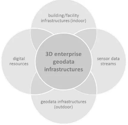
From the technical SDI-perspective, the space-component in smart production environments can be realized through the use of digital (indoor) building/facility infrastructures. Considering the data together with space-time components providing contextualization, an Enterprise SDI should contain four major parts, namely 1.) geodata infrastructures (outdoor), 2.) building/facility infrastructures (indoor), 3.) sensor data streams as well as 4.) digital resources (see Fig. 1).
Figure 1. Components of a 3D Enterprise SDI
On the one hand, building/facility infrastructures and geodata infrastructures provide information on the structure and connections of enterprise sites. On the other hand, they build up the base infrastructure to link sensor data streams and digital resources to the physical world.
To build up an (indoor) building/facility infrastructure for the framework of 3D Enterprise SDIs, we identified five requirements that need to be considered in the design and implementation:
Be 3D (R1). Within indoor production environments, a visualisation in 3D brings major advantages. Most buildings consist of several floors, however, production environments are more complex. Machines with complex structures and overlapping parts can only be displayed in a meaningful manner using 3D. Additionally, human perception is based primarily on three-dimensional objects. Therefore, a digital 3D representation supports a quick orientation in space and can be used to provide information in a context-based manner (Isikdag et al., 2013).
(Re-)use of available data (R2). In most cases, building data of production environments is already available in isolated data silos which need to be mobilised, harmonized and made available for future (re)use. In contrast to other approaches that acquire the building data using LIDAR and other techniques, a (re)use of available data such as architectural models reduces the required efforts. In combination with further techniques, the data can be enriched with additional information.
Use GIS-Principles and Standards (R3). GIS (Geographic Information Systems) have proven to be an integration domain for all kinds of data. Using spatio-temporal information for combination purposes, data from different domains can be harmonized and fit together to find new patterns and relationships. Doing so by applying methods and standards from the GIS-domain, data from production processes does not remain encapsulated and thus might be reused for other use cases once it has been harmonized.
Be adaptive/dynamic (R4). The situation in enterprises is rapidly changing. Not only moving elements (inventory), but also some structural elements, such as walls, might be altered. Possible modifications need to be considered from start to end to keep the information up-to-date and quality-assured. To be consistent, changes should be implemented at the organisational starting point where current data gets implemented. Furthermore, not only the data itself should be considered, but also the surrounding organisation of departments in charge of data use/collection, etc.
Identify and implement all necessary indoor information (R5). Current approaches on AEC (Architecture, Engineering, Construction)/GIS-integration each focus on elements required by a specific use case. The production environment has specific elements that need to be modelled and integrated to get a big picture of all processes. These elements do not only include structural parts of production sites, but also the machines and corresponding sensors as well as associated data in form of digital resources.
The presented requirements are necessary for the design and implementation of resilient (indoor) building/facility infrastructures. To fulfil these requirements, the following chapter describes strategies that can be used to meet the challenges posed during an implementation.
4. BUILDING MODELLING FOR ENTERPRISE SDIS
4.1 Three-dimensionality – Why 3D? (R1)
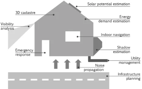
A trend towards the use of 3D data can be observed (El-Mekawy, 2010; Lee et al., 2013; Tashakkori et al., 2015). According to El-Mekawy (2010), large GIS companies (Oracle, ESRI, Safe Software, etc.) recognize the importance of 3D data models and functionalities that go beyond visualization purposes. The increasing interest can not only be found in the development of navigation systems, but in a range of applications (see Fig. 2) which vary from 3D cadastres and indoor navigation to shadow estimation and visibility analysis.
Using 3D instead of 2D improves the planning of rescue operations (Tashakkori et al., 2015), helps to “understand complex spatial and functional relationships in the contemporary 3D city” (Isikdag et al., 2013) and enhances the visual perception of complex information (Thill et al., 2011).
Figure 2. Use cases for 3D building models (adapted from Biljecki et al. (2015))
The visual effects on map users were the subject of several studies, mainly in the realm of city modelling and city planning. Thus, Rautenbach et al (2015) conducted a qualitative user experiment that tried to identify the impact of the 3D model complexity on user orientation and cognitive maps. Despite the fact that the user conditions were not controlled, they concluded that “inappropriately designed 3D models do affect the performance […of] orientation […] and recall” (Rautenbach et al. 2015) and that users tend to overestimate their spatial cognition abilities.
Herbert and Chen (2013), however, compared the usefulness of 2D and 3D maps for different urban planning tasks. Their result was that 3D visualizations may be more appropriate for complex tasks, while 2D is the preferred visualization for simple problems. Overall, users might prefer a combined visualization in 2D and 3D.
Despite the demand of detailed 3D-information, the collection (El-Mekawy, 2010; Volk et al., 2014) and use (Biljecki et al., 2015) of this data still remains a challenge.
4.2 Data Acquisition (R2)
To acquire detailed data for 3D building models, several methods are available. According to Biljecki et al. (2015), information can be “ […] derived from various acquisition techniques, for instance, photogrammetry and laser scanning, extrusion from 2D footprints, synthetic aperture radar, architectural models and drawings, handheld devices, procedural modelling, and volunteered geoinformation”.
As building information for Enterprise SDIs should provide an accurate reflection of reality, procedural modelling is not an option as this creates rule-based models, not “as-is” models. Additionally, handheld devices can be handy to gather information quickly, but might not be as detailed.
Buildings are designed and constructed by users of the AEC-industry. Therefore, data is available for buildings in this domain from the earliest design phase and often until the demolition of a building and thus, throughout the whole lifecycle. For a long time, the AEC-domain used CAD (Computer-Aided Design) plans. Today’s efforts in this sector concentrate on the implementation of BIM (Building Information Modelling) to provide interoperability of information for all actors involved (El-Mekawy, 2010; Isikdag et al., 2013; Volk et al., 2014). In contrast to CAD, BIMs ISPRS Annals of the Photogrammetry, Remote Sensing and Spatial Information Sciences, Volume IV-2/W1, 2016
follow object-oriented principles (Isikdag et al., 2008) and are more detailed than CAD-plans (El-Mekawy, 2010). On the one hand, this makes BIM more suitable for GIS-integration. On the other hand, it makes BIM more complex and complicated for integration and harmonization tasks (Zlatanova and Isikdag, 2009). While BIM is not a model itself, but rather a paradigm, using the ISO standard “Industry Foundation Classes” (IFC) has proven to be the preferred method of implementing BIMs (Zlatanova and Isikdag, 2009).
However, BIM/GIS integration is a very important topic: Zlatanova and Isikdag (2009) performed a SWOT analysis regarding this topic. While they recognized some challenges on the technical (e.g. different representations of objects, coordinates, class differences) and the domain perspective (e.g. privacy, information overload), the advantages predominate. Musliman et al. (2010) identify the strengths of using GIS for building information as GIS “[…] is an appropriate technology for managing construction projects and can improve the construction planning and design efficiency by integrating locational and thematic information in a single environment”.
Integration tasks provide new possibilities for both domains as BIM/IFC “contains very detailed and semantically rich information of a construction” (Rafiee et al., 2014) which is “[…] usually not integrated with its surrounding information” (Rafiee et al., 2014) while “Geographic Information Systems (GIS), on the other hand, are capable of performing spatial analysis using the physical and functional spatial representations of an environment” (Rafiee et al., 2014) and thus, analysis might be more comprehensive “due to the complementary nature of the detailed construction information from the BIM and the information about the surrounding area” (Rafiee et al., 2014).
Sometimes, BIM is not available for existing buildings (Volk et al., 2014). In this case, data might be gathered using non-contact (image-based, range-based, and other) or non-contact (manual or other) techniques (Volk et al., 2014). This does not mean that it is one technique or the other. Data from non-contact techniques such as photogrammetry and laser scans might also be used in combination with pre-existing BIMs or other object-based models. The result would be a model that provides a realistic view (through coloured point-clouds) while being touchable and object-based (through the underlying BIM). Today, scanning in 3D becomes easier through products such as FARO 3D scanners, Samsung Gear 360 or smartphones with integrated stereo cameras (LG Optimus 3D, HTC Evo 3D). Therefore, non-contact techniques are not restricted to professionals anymore.
4.3 Target Models (R3)
While previous chapter described the models from the AEC-domain, this chapter is about GIS-standards on buildings. The most important standards in the GIS-domain concerning buildings are CityGML and the INSPIRE Building model.
CityGML. To model the indoor environment, not only BIM and CAD from the AEC-domain are available. In the GIS-domain, the OGC developed the “City Geography Markup Language”, an XML-based format to describe and model 3D cities in five levels of detail (LoDs). The first version of CityGML was released in 2008, a revised version (CityGML 2.0.0) in 2012 (OGC, 2012).
In CityGML, each object has at least three attributes: class, function, and usage. The OGC proposes code lists developed by the Special Interest Group 3D (SIG 3D) that contain a description (e.g. “habitation” or “industry”) and a name (numbered from e.g. 1000 to 1180) (SIG 3D, 2012a). As the OGC explicitly states, “[…] this annex [Code lists proposed by the SIG 3D; author’s note] is non-normative and the presented code lists are neither mandatory nor complete” (OGC, 2012:223).
For “BuildingFurniture”, the list of class attribute values contains 19 possible entries (SIG 3D, 2012a). In terms of Enterprise SDIs, the classes “1010 sanitation”, “1110 maintenance, waste management”, “1150 storage” and “1160 industry” are the most important ones.
An additional code list contains descriptions and numbers for the function (SIG 3D, 2012b) as well as the usage (SIG 3D, 2012c). The list for both attributes is the same with the “function” being the “intended purpose or usage of the object” (OGC, 2012:51) and the “usage” that “defines its real or actual usage” (OGC, 2012:51). The particular code list of “BuildingFurniture” follows a hierarchical structure. Codes of “main elements” are ending with “00”: 1000 cupboard, 1100 shelf, 1200 table, etc. An example for a full hierarchy: 2500 technical furniture, 2520 tank, 2524 fuel tank where “fuel tank” is a subclass of a “tank” which again is a child of “technical furniture”.
While CityGML is a ubiquitous standard that aims at the representation of 3D cities and their inventory, issues raised about the inconsistency of the LoDs (Biljecki et al., 2014) as well as the size of CityGML files which are (compared to IFC) “between 11 to 38 times as big” (Berlo and Laat, 2010).
INSPIRE Building. Another building standard coming from the GIS-domain is the INSPIRE Building model. INSPIRE (Infrastructure for Spatial Information in the European Union) is a directive of the European Union (Directive 2007/2/EC) that aims at “establishing an infrastructure for spatial information in Europe to support Community environmental policies, and policies or activities which may have an impact on the environment” (European Union (EU), 2016b). In total, INSPIRE consists of Technical Guidelines I-III that contain 34 data specifications on different topics, amongst them is D2.8.III.2, the data specification on buildings.
INSPIRE Buildings or “TWG BU model” (Technical Working Group Building model) is based on the OGC CityGML and includes a mapping scheme to exchange data between both models (INSPIRE TWG BU, 2013). According to Gröger and Plümer (2012), the “future harmonization, coordination and bi-directional transformation between both models is an important issue”.
While CityGML provides the possibility of adding movable furniture elements, such elements do not exist in the TWG BU model. The reason behind this is its origin from the outdoor environment modelling side. For the use cases defined for INSPIRE, furniture elements do not play a major role.
The described models are the main standards that need to be considered when trying to model buildings for further use in GI-systems. A harmonization of current standards from AEC (IFC) and GIS (CityGML/TWG BU) is desirable because “[…] IFC focuses on the construction and design of buildings and ISPRS Annals of the Photogrammetry, Remote Sensing and Spatial Information Sciences, Volume IV-2/W1, 2016
provides construction elements like slabs, beams, or walls. […] In contrast, the definitions of CityGML [and thus, TWG BU, too; author’s note] describe how buildings are observed or used” (Gröger and Plümer, 2012).
4.4 Workflow models (R4)
R2 and R3 showed the challenges posed by the use of different data models in the AEC and the GIS-domain. In the case of production environments, data is often acquired and implemented by CAD-specialists who need the plans for their own internal business processes. To keep the data up-to-date throughout the whole process, starting from design (AEC) to information use (GIS), a workflow model needs to be defined that automatically pushes changes from where they occur through the whole pipeline and into the SDI.
On the organizational side, the processes of indoor data acquisition, transformation, provision, etc. need to be defined and implemented for each department and responsible party. This can be done in an understandable manner using the Business Process Modelling Notation (BPMN) as defined by the Object Management Group (OMG) (OMG, 2011). Using such a notation enables the communication of business processes to “other business users, process implements, customers, and suppliers” (OMG, 2011:1).
On the technical side, there is not only the need for a definition of a harmonized data structure, but also for common semantics so that all the actors along the pipeline can communicate. Mapping between different formats provided by various domains can be done by using spatial ETL (Extract, Transfer, Load)-tools such as the Feature Manipulation Engine (FME) by the company Safe Software or the HUMBOLDT Alignment Editor (HALE) developed by the data harmonisation panel. For the technical processes, start and end models need to be identified in advance, which is done during the creation of the Business Process Model.
Additionally, the quality of the data along the processes needs to be checked for inconsistencies and mistakes that might occur. For quality assurance, standards such as the ISO 9000 family are available. Using them for quality management assures the provision of data in a secured and constantly high manner.
4.5 Available Approaches/Related Work (R5)
Existing approaches for AEC/GIS-integration focus on the requirements of their specific use case. Coming from the application area of BIM for emergency situations, BO-IDM (BIM Oriented Indoor Data Model) and IESM (3D Indoor Emergency Spatial Model) focus on the definition of elements required by first responders (Isikdag et al., 2013; Tashakkori et al., 2015). Therefore, they provide fine-grained definitions of specific elements such as the material, available sensors (detectors), fire fighting equipment as well as the basic structural elements of the building.
Other studies mainly focus on the integration of IFC and CityGML. El-Mekawy and Östman (2010) and El-Mekawy et al. (2012) developed the UBM (Unified Building Model) for mapping between IFC and CityGML. Rafiee et al. (2014) transformed an IFC model into a GIS environment to perform view and shadow analyses. Comparable studies show that it is not only possible to map and automatically transform between
both domains, but also that there is much potential that could be revealed.
Regarding building information for production or facility environments, there are only a limited number of studies available. Bleifuss et al. (2009) successfully developed a CityGML extension (ADE) for CAFM (Computer Aided Facility Management) with a test scenario in city of Munich. A broader study in this area was performed by Ilter and Ergen (2015). They did a systematic literature review on the topic “Building information modelling (BIM) for Building Refurbishment and Maintenance” (Ilter and Ergen, 2015) with the conclusion that “studies related to BIM applications in maintenance and especially refurbishment are relatively recent. However, the trend in published articles shows that the interest is continuously growing” (Ilter and Ergen, 2015). Furthermore, they identify the subtopics as being:
1. Building survey and as-built BIM 2. Modelling and managing energy 3. Design assessment
4. Access to and integration of maintenance information and knowledge
5. Information exchange and interoperability
Even if this list is from the FM-perspective, it covers main parts that we considered for the our approach, such as the identified interoperability issues (in our case with GIS), but also tasks such as automated equipment identification and data capture using RFID or barcodes as well as missing properties in IFC are an issue for both FM and in GIS-integration.
Another study by Musliman et al. (2010) implemented a system that transforms CAD data into a geo-DBMS (geographical database management systems) to perform a comparison between the planned and the constructed building in 3D. Furthermore, they state that “[…] managing construction is quite demanding and needs rapid spatial information on the spot […]. It would be great if a construction project is managed by decision makers using 3D-GIS where the required information is in the form of a 3D display of a dynamic 3D spatial query and analysis” (Musliman et al., 2010).
While these studies tackle the general integration tasks or the integration tasks for the use cases of emergency or facility management, production environments and processes are not studied, yet. Some parts of this specific use case is overlapping with facility management, such as that up-to-date information is required and that the integration of AEC/GIS is an important topic. However, a major issue is the lack of indoor inventory definitions or as called in CityGML “BuildingFurniture”. In production environments, the indoor inventory is the dynamic layer where tasks are performed, data is created and which has a high optimization potential. Thus, the next chapter is about our approach to tackle these issues.
5. OLS3D-APPROACH
In contrast to the previous approaches for modelling buildings presented in this paper, our approach “OLS3D” (Organizing Large-Scale 3D geodata) will tackle the use case of organizing building information models in a sustainable manner for production environments and smart factories in the context of Industrie 4.0 (e.g. for linking with IoT data streams).
5.1 OLS3D development
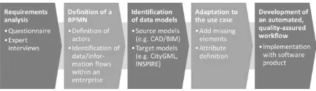
As shown in Fig. 3, the workflow to design the OLS3D framework consists of five steps.
Figure 3. Workflow for the development of OLS3D
First, a requirements analysis has to be performed using questionnaires in combination with expert interviews to identify the structure of the organizations and their specific requirements and compare them with the requirements identified in chapter 3. This step should assure that every important element and actor is considered in the model and to identify further elements that have not been part of the discussion, yet.
Using the results of the requirements analysis, a BPMN (see chapter 4.4) can be defined that takes into account the whole process from data acquisition to use and updating. Additionally, the BPMN identifies and visualizes the data and information flows between and within different departments of an enterprise. Through the development of a BPMN and with the results of the requirements analysis, the source (e.g. BIM/IFC, CAD) and target models (e.g. CityGML, INSPIRE) can be identified.
When the process is analysed as well as the source and target models, they can be adapted to fit the use case. This step might include the definition of a CityGML ADE or a new intermediate model as transitioning step for the harmonization tasks. This model, in contrast to others, need to include the inventory and assets found within a production environment, such as machines or products that move within a production site.
Afterwards, the transition process can be automated through mapping of elements by using a spatial ETL like FME or a harmonization toolkit such as HALE. Furthermore, using automated techniques provides the possibility of integrating quality assurance mechanisms to provide a constantly high data quality.
The framework should then be implemented in a prototypical manner to test its usefulness for the Common operational Picture (CoP) for decision makers in production environments. For implementation, a reference model, such as the Reference Model of Distributed Processing (RM-ODP) developed by the Organization for the Advancement of Structured Information Standards (OASIS) is important to consider. Using a reference architecture helps with the design of the whole socio-temporal enterprise architecture.
To tackle all elements of the system, the RM-ODP consists of five viewpoints that consider all parts needed for an SDI, not only on the technological, but also on the organizational side. The viewpoints of RM-ODP are the following (OASIS, 2009):
Enterprise viewpoint: “requirement capture and early design of distributed system” (OASIS, 2009)
Information viewpoint: “conceptual design and information modelling” (OASIS, 2009)
Computation viewpoint: “software design and development” (OASIS, 2009)
Engineering viewpoint: “system design and development” (OASIS, 2009)
Technology viewpoint: “technology identification, procurement, installation” (OASIS, 2009)
In the course of the development of the OLS3D framework, all these viewpoints need to be considered from start to end to guarantee a smooth development and the inclusion of all important aspects.
5.2 Linking strategies for data and contextual environment
Following the steps presented above, the outcome is a comprehensive and well-defined infrastructure. This infrastructure represents the base for the integration of Industrie 4.0-principles such as sensor measurements, M2M-communication and digital documents with GIS-technologies to support decision-making and relieve workers from an information-overload.
Linking of data is not new, there is a whole field of research developing methods and approaches to link data in an open manner to create value from structured information. This research field is called “Linked (Open) Data” (LD) (Bizer et al., 2011).
Starting at the lowest point of semantic data representation systems, semantic data can be formalized using vocabularies, taxonomies, Resource Description Frameworks (RDF) or Simple Knowledge Organization Systems (SKOS). Each of these systems is a step further in the direction of structured data.
In terms of sensor data, the information is already structured and can be linked directly, while other, more unstructured data is harder to integrate. This is especially the case for maintenance documents that provide information on the maintenance processes of production machines. On the one hand, this might include the manuals. On the other hand, this can also comprise the documentation done by a worker that maintained the machine.
To link such data, Vockner and Mittlböck (2014) proposed geo-enrichment and semantic geo-enrichment methods “for an improved discovery and linked-data eligibility”. This cannot only be done with spatial datasets, but also using PDFs. Using geo-enrichment and text-matching mechanisms in combination with Enterprise SDIs and digital resources might facilitate the information provision for the user and thus enhance the situational awareness in production environments.
Using machine names as attribute in the spatial data model in combination with the recommended geo-enrichment-strategy will provide useful results for data discovery and will optimize production processes.
5.3 Experimental Implementation
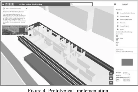
We implemented a first prototype of a web-based 3D building representation that includes data streams of real-time indoor-positioning (Fig. 4).
It has been implemented with the ESRI JavaScript API 4.0. This web-based representation can be highly customized in order to ISPRS Annals of the Photogrammetry, Remote Sensing and Spatial Information Sciences, Volume IV-2/W1, 2016
provide the “best possible view” (not distracting, no information overload, depending on the role, supporting, etc.) depending on the user’s context.
Figure 4. Prototypical Implementation
The building model was acquired using CAD-plans that were transformed using Safe FME Desktop into a geodatabase which then has been extruded and uploaded as ESRI webservice. We implemented the prototype for the use case of indoor positioning in production facilities. The indoor position is generated by a smartphone app we developed. According to the users’ positions, contextual information is provided.
When an authorized maintenance worker approaches a machine, a website is shown on the worker’s portable smart device showing information and status of the machine as well as links to corresponding maintenance documents. On the one hand, the contextual provision of the “right” information on the smart device assists the worker in the maintenance tasks. On the other hand, the big picture given by the map and the current status of the production line supports the management in their decision-making.
As it is easier for humans to perceive 3D rather than 2D maps, we implemented the prototype using 3D. Specifically for production environments, a machine consisting of several stacked parts can be represented in a more comprehensible manner using 3D.
6. CONCLUSION
The changes and new paradigms accompanying the shift to Industrie 4.0 and the IoT pose new challenges and questions. The industry is a sector with specific requirements that have to be tackled with new strategies for organizing data, building models etc. to integrate different sources of information. As an essential part, spatio-temporal referencing can be used to enhance contextualization of IoT data and data streams. The geospatial (work) environment can be used as context, still in many cases this information is not available in a corresponding manner and has to be modelled first.
Within GIS and AEC, different schemes have been established in the past years to model building and site areas. In order to leverage the information in an interoperable manner we need mapping schemes e.g. between BIM/CAD (AEC) and CityGML/INSPIRE (GIS). Additionally, special strategies are needed like semantically harmonized ‘dictionaries’ for assets and machinery to establish a sophisticated industrial facility
building model serving the needs of an integrated assessment of the production chain.
Once such a building model has been developed, it can be integrated into a broader context of industrial facility Enterprise SDIs where the required data and data streams are organized to be shared amongst various departments of industrial companies. In this paper, we proposed a workflow to design and implement such an industrial building model and its data streams to support and enhance data and information flows within production facilities.
ACKNOWLEDGEMENTS (OPTIONAL)
This paper was written as part of the industry-dissertation research project “Organizing Large-Scale 3D geoinformation (OLS3D) – Transitioning to geo-enabled IT-content infrastructures leveraging SDI concepts” (FFG-Project 853938), financially supported by the Austrian Research Promotion Agency (FFG) and the Research Studios Austria GmbH (RSA FG).
REFERENCES
Bellinger, G., 2004. Knowledge Management—Emerging
Perspectives,
http://www.systems-thinking.org/kmgmt/kmgmt.htm (09.05.2016).
Berlo, L.v., Laat, R.d., 2010. Integration of BIM and GIS: The development of the CityGML GeoBIM extension, In: Kolbe, T.H., König, G., Nagel, C. (Eds.), Advances in 3D Geo-Information Sciences. Springer-Verlag, Berlin Heidelberg, pp. 211-226.
Biljecki, F., Ledoux, H., Stoter, J., Zhao, J., 2014. Formalisation of the level of detail in 3D city modelling. Computers, Environment and Urban Systems 48, 1-15.
Biljecki, F., Stoter, J., Ledoux, H., Zlatanova, S., Çöltekin, A., 2015. Applications of 3D City Models: State of the Art Review. ISPRS International Journal of Geo-Information 4, 2842.
Bizer, C., Heath, T., Berners-Lee, T., 2011. Linked Data: The Story so Far, In: Amit, S. (Ed.), Semantic Services, Interoperability and Web Applications: Emerging Concepts. IGI Global, Hershey, PA, USA, pp. 205-227.
Bleifuss, R., Donaubauer, A., Liebscher, J., Seitle, M., 2009. Entwicklung einer CityGML-Erweiterung für das Facility Management am Beispiel Landeshauptstadt München, Angewandte Geoinformatik 2009: Beiträge zum 21. AGIT-Symposium. Wichmann, Heidelberg.
Coleman, D.J., Rajabifard, A., Kolodziej, K.W., 2016. Expanding the SDI environment: comparing current spatial data infrastructure with emerging indoor location-based services. International Journal of Digital Earth, 1-19.
Deuse, J., Weisner, K., Hengstebeck, A., Busch, F., 2015. Gestaltung von Produktionssystemen im Kontext von Industrie 4.0, In: Botthof, A., Hartmann, E.A. (Eds.), Zukunft der Arbeit in Industrie 4.0. Springer Vieweg, Berlin, pp. 99-109.
El-Mekawy, M., 2010. Integrating BIM and GIS for 3D City Modelling: The Case of IFC and CityGML, KTH, School of Architecture and the Built Environment (ABE), Urban Planning and Environment, Geoinformatics. KTH, Stockholm.
El-Mekawy, M., Östman, A., 2010. Semantic Mapping : An Ontology Engineering Method for Integrating Building Models in IFC and CityGML. Proceedings of the 3rd ISDE DIGITAL EARTH SUMMIT.
El-Mekawy, M., Östman, A., Hijazi, I., 2012. A Unified Building Model for 3D Urban GIS. ISPRS International Journal of Geo-Information 1, 120.
European Union (EU), 2016a. ICT Research & Innovation, https://ec.europa.eu/programmes/horizon2020/en/area/ict-research-innovation (09.05.2016).
European Union (EU), 2016b. INSPIRE Directive, http://inspire.ec.europa.eu/ (09.05.2016).
FGDC, 2015. National Spatial Data Infrastructure, https://www.fgdc.gov/nsdi/nsdi.html (10.05.2015).
Gröger, G., Plümer, L., 2012. CityGML - Interoperable semantic 3D city models. ISPRS Journal of Photogrammetry and Remote Sensing 71, 12-33.
Ilter, D., Ergen, E., 2015. BIM for building refurbishment and maintenance: current status and research directions. Structural Survey 33, 228-256.
INSPIRE TWG BU, 2013. D2.8.III.2 Data Specification on
Buildings - Technical Guidelines,
http://inspire.ec.europa.eu/documents/Data_Specifications/INS PIRE_DataSpecification_BU_v3.0.pdf.
Isikdag, U., Underwood, J., Aouad, G., 2008. An investigation into the applicability of building information models in geospatial environment in support of site selection and fire response management processes. Advanced Engineering Informatics 22, 504-519.
Isikdag, U., Zlatanova, S., Underwood, J., 2013. A BIM-Oriented Model for supporting indoor navigation requirements. Computers, Environment and Urban Systems 41, 112-123.
Kleinhempel, K., Satzer, A., Steinberger, V., 2015. Industrie 4.0 im Aufbruch? Ein beispielhafter Ausschnitt aus dem betrieblichen Stand, Mitbestimmungsförderung.
Lasi, H., Fettke, P., Kemper, H.-G., Feld, T., Hoffmann, M., 2014. Industrie 4.0. WIRTSCHAFTSINFORMATIK 56, 261-264.
Lee, S.Y., Majid, Z., H., S., 2013. 3D Data Acquisition for Indoor Assets using Terrestrial Laser Scanning. ISPRS 8th 3DGeoInfo Conference & WG II/2 Workshop II-2, 221-226.
Musliman, I.A., Abdul-Rahman, A., Coors, V., 2010. Incorporating 3D spatial operator with building information models in construction management using Geo-DBMS. International Archives of the Photogrammetry, Remote Sensing and Spatial Information Sciences - ISPRS Archives 38, 147-154.
OASIS, 2009. Views and Viewpoints, https://wiki.oasis-open.org/soa-rm/TheArchitecture/ViewsAndViewpoints (09.05.2016).
OGC, 2012. OGC City Geography Markup Language (CityGML) Encoding Standard, Version 2.0.0.
OMG, 2011. Business Process Model and Notation (BPMN) Version 2.0, http://www.omg.org/spec/BPMN/2.0/PDF.
Rafiee, A., Dias, E., Fruijtier, S., Scholten, H., 2014. From BIM to Geo-analysis: View Coverage and Shadow Analysis by
BIM/GIS Integration. Procedia Environmental Sciences 22, 397-402.
Ramsauer, C., 2013. Industrie 4.0 - Die Produktion der Zukunft. WINGbusiness 3, 6-12.
SIG 3D, 2012a. Code List for the attribute "class" of the feature
type "BuildingFurniture",
http://www.sig3d.org/codelists/standard/building/2.0/BuildingF urniture_class.xml (10.05.2016).
SIG 3D, 2012b. Code List for the attribute "function" of the feature type "BuildingFurniture", http://www.sig3d.org/codelists/standard/building/2.0/BuildingF urniture_function.xml (10.05.2016).
SIG 3D, 2012c. Code List for the attribute "usage" of the feature type "BuildingFurniture", http://www.sig3d.org/codelists/standard/building/2.0/BuildingF urniture_usage.xml (10.05.2016).
Simon, A., 2014. Modern Enterprise Business Intelligence and Data Management. A Roadmap for IT Directors, Managers, and Architects. Elsevier, USA.
Tashakkori, H., Rajabifard, A., Kalantari, M., 2015. A new 3D indoor/outdoor spatial model for indoor emergency response facilitation. Building and Environment 89, 170-182.
Thill, J.-C., Dao, T.H.D., Zhou, Y., 2011. Traveling in the three-dimensional city: applications in route planning, accessibility assessment, location analysis and beyond. Journal of Transport Geography 19, 405-421.
Vockner, B., Mittlböck, M., 2014. Geo-Enrichment and Semantic Enhancement of Metadata Sets to Augment Discovery in Geoportals. ISPRS International Journal of Geo-Information 3, 345.
Volk, R., Stengel, J., Schultmann, F., 2014. Building Information Modeling (BIM) for existing buildings - Literature review and future needs. Automation in Construction 38, 109-127.
Zlatanova, S., Isikdag, U., 2009. A SWOT analysis on the implementation of Building Information Models within the geospatial environment, Urban and Regional Data Management. CRC Press.