DEVELOPMENT OF A SELF-LOCALIZATION METHOD
USING SENSORS ON MOBILE DEVICES
T. Fuse a, *, K. Matsumoto a
a
Dept. of Civil Engineering, University of Tokyo, Hongo 731, Bunkyoku, Tokyo, 1138656, Japan [email protected], [email protected]
Commission V, WG V/4
KEY WORDS: Sensor Fusion, Self-Localization, Mobile Devices, Augmented Reality, Visualization, Navigation
ABSTRACT:
Recently, development of high performance CPU, cameras and other sensors on mobile devises have been used for wide variety of applications. Most of the applications require self-localization of the mobile device. Since the self-localization is based on GPS, gyro sensor, acceleration meter and magnetic field sensor (called as POS) of low accuracy, the applications are limited. On the other hand, self-localization method using images have been developed, and the accuracy of the method is increasing. This paper develops the self-localization method using sensors, such as POS and cameras, on mobile devices simultaneously. The proposed method mainly consists of two parts: one is the accuracy improvement of POS data in itself by POS sensor fusion based on filtering theory, and another is development of self-localization method by integrating POS and camera. The proposed method combines all POS data by using Kalman filter in order to improve the accuracy of exterior orientation factors. The exterior orientation factors based on POS sensor fusion are used as initial value of ones in image-based localization method. The image-based self-localization method consists of feature points extraction / tracking, coordinates estimation of the feature points, and orientation factors updates of the mobile device. The proposed method is applied to POS data and images taken in urban area. Through experiments with real data, the accuracy improvement by POS sensor fusion is confirmed. The proposed self-localization method with POS and camera make the accuracy more sophisticated by comparing with only POS sensor fusion.
1. INTRODUCTION
Recently, development of high performance CPU, cameras and other sensors on mobile devises have been used for wide variety of applications. One of the most popular applications is augmented reality (AR). The AR technique superimposes various data on the scene which the users see at the time instead of comprehensive and detailed three dimensional modelling such as virtual reality. The AR uses sequential images taken from same view points of users as environmental scene, and then reality of visualization increase compared with the virtual reality. AR requires self-localization, namely orientation of the mobile device.
Since the self-localization of the mobile device is based on GPS, gyro sensor, acceleration meter and magnetic field sensor (called as position and orientation system (POS) in this paper) of low accuracy, the applications are limited to tags superimposition on the sequential images.
On the other hand, self-localization method using images have been developed, and the accuracy of the method is increasing. The method, however, requires initial values of the orientation factors and distance of baseline. GCPs can be used to specify the absolute coordinates. But it takes a lot of time and effort, and the applicability is restrictive.
This paper develops the self-localization method using sensors, such as POS and cameras, on mobile devices simultaneously. The proposed method mainly consists of two parts: one is the accuracy improvement of POS data in itself by POS sensor fusion based on filtering theory, and another is development of self-localization method by integrating POS data and images.
2. POS SENSOR FUSION 2.1 Overview
In this study, an iPhone4s is used as a mobile device. The center of the mobile device is defined as the origin of the coordinate system for the mobile device. Z axis is set as the direction of gravitational force, and X axis is north-seeking. The rotations about the axis X, Y, Z (roll, pitch, yaw) are expressed as , , , respectively.
As mentioned before, POS includes GPS, gyro sensor, a c c e l e r a t i o n m e t e r a n d m a g n e t i c f i e l d s e n s o r . T he corresponding data are three dimensional coordinates of the sensor (longitude: E (degree), latitude: N (degree), height: h (m)), angular velocity (x, y, z (rad/s)), acceleration
(ax, ay, az (G)) and triaxial angle (ti (rad)), respectively.
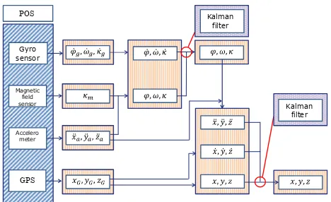
Normally, each sensor is used separately (Daehne and Karigiannis, 2002) or limited in parts of sensors (Agrawal and Konolige, 2006; Kourogi and Kurata, 2005; Wagner et al., 2009). The proposed method combines all sensors data in order to improve the accuracy of exterior orientation factors. Figure 1 shows the pipeline of the POS data fusion.
2.2 Filtering method of rotation
Initial rotation of the mobile device is calculated from acceleration meter and magnetic field sensor, and rotation during movement is calculated from the gyro sensor. The data of gyro sensor have drift error. In order to correct the drift error, filtering method with the data of the acceleration meter and
Gyro
Figure 1. Flow of the POS data fusion
the magnetic field sensor is applied. In this step, the data of such sensors are integrated by using Kalman filter (Schall et al., 2009). The assumption, that the mobile sensor moves linearly, is accepted here.
2.2.1 Calculation of rotation: When the mobile device remains stationary, the acceleration meter detect only acceleration of gravity g. The relationships between the acceleration and initial rotation (0, 0, 0) can be expressed
From the equation (1), roll and pitch can be calculated.
1 1
Yaw should be transformed according to the above defined coordinate system:
0 ti
(3)
For calculation of rotation during movement, data of the gyro sensor are added to the initial rotation. Derivatives of the rotation with respect to time (, , ) are represented by using angular velocity.
0 sin cos
1
0 cos cos sin cos
cos
cos sin sin cos sin x
By integrating equation (4), the rotation during movement can be acquired.
2.2.2 Filtering of rotation: According to integration, the error is accumulated. It is important to point out here that the acceleration meter and the magnetic field sensor are free from such cumulative error. With the acceleration meter and the magnetic field sensor, the rotation during movement is corrected. Filtering theory is applied in order to correct the cumulative error.
For the efficient computation, Kalman filter is adopted as filtering method (Ristic et al., 2004). The filtering method achieves POS sensor fusion.
The Kalman filter consists of dynamic equation and observation equation as follows:
xt = Ft xt-1 + Gt vt (6)
In this study, these vectors and matrices are constructed as follows:
cos sin sin cos sin m
suffix a expresses data of the acceleration meter, and m data of the magnetic field sensor.
Since the Kalman filter is based on linear equation with normal distribution, the equations can be solved analytically.
xt|t-1 = Ft xt-1|t-1 (9)
Vt|t-1 = Ft Vt-1|t-1FTt + Gt Qt GtT (10)
Kt = Vt-1|t-1 HtT (Ht Vt-1|t-1HtT + Rt)-1 (11)
xt|t = xt|t-1 + Kt (yt - Ht xt|t-1) (12)
Vt|t-1 = Vt|t-1 - Kt Ht Vt|t-1 (13)
State vector xt|t is a result of filtering method for rotation.
2.3 Filtering method of position
Although the position of the mobile device is measured with GPS directly, the accuracy of the position can be improved by relating to the other sensors used for rotation calculation. Here the Kalman filter is also utilized with all POS data to estimate the position.
2.3.1 Calculation of position: Data of GPS are directly used for initial position of the mobile device. For measurement of position during movement, data of the acceleration meter is added to the initial position.
The relationships between the measured acceleration and second derivative of position (X , Y, Z) can be expressed as
Here, rotation matrices are represented as R. Additionally, velocity ( X , Y, Z ) can be calculated from data of GPS.
where, Δt is GPS data acquisition interval. By using both of
velocity and acceleration, position at time t is calculated.
1 1 1
2.3.2 Filtering of position: In the similar fashion of filtering method of rotation, Kalman filter is applied to correct position. Dynamic equation and observation equation are same as equation (6), (7). State vector, observation vector and matrix Ft
are set for position filtering.
2
Analytical solution of the dynamic and observation equations can be conducted in the same manner of equations (9) – (13).
3. INTEGRATING METHOD OF IMAGES The position and rotation based on POS sensor fusion are used as initial value of the orientation factors in image-based self-localization method. The position is already represented in the geodetic coordinate, and then the distance of baseline is also supplied in the real scale. The image-based self-localization method consists of feature points extraction / tracking, three dimensional coordinates estimation of the feature points, and orientation factors updates of the mobile device. Figure 2 shows an overview of the proposed method.
3D reconstruction
Optimization of pos/rot by bundle adjustment Estimation pos/rot by combining FPs extraction
FPs tracking
Error adjustment by filtering
Figure 2. Flow of the POS and camera integration
3.1 Feature points extraction / tracking
Recently, sophisticated feature points extraction / tracking algorithms have been developed. One of the most reliable algorithms is SURF (Speeded-UP Robust Features) (Bay et al., 2008). The SURF algorithm is applied to feature points extraction / tracking.
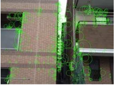
The SURF algorithm uses box filter, which approximates Hessian-Laplace detector, for making integration images. The integration image improves computational speed. Additionally, points included in a certain radius circle are added for calculation of norm, and then orientation is adopted with maximum norm. According to above mentioned feature, the SURF is robust against scaling and rotation. Finally, image is divided into 4 x 4 block, and then differences of features are represented as 64 dimension SURF features by using those gradient and amplitude (
dx, dx, dx, dy ). Figure 3 shows an example of feature points extraction by the SURF in our experiments.Figure 3. Feature points extraction by SURF
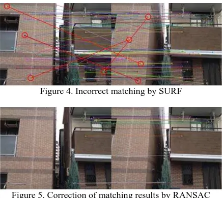
Even if the SURF is applied to feature points extraction and tracking, incorrect matching points are still exist. Additionally, feature points tracking is refined by using not only adjacent frames also sequential frames. Firstly, extracted feature points are searched in sequence between adjacent frames. After the tracking process is conducted within a certain number of frames, position of feature points are re-projected into first frames. If the displacement between first and last position of the points is larger than a threshold, the feature points are discarded. With the result of the matching, three dimensional coordinates of the feature points can be calculated. If the depth of the points is larger than a threshold, the feature points are also discarded. Finally, the remaining points are accepted as feature points.
After the above mentioned thresholding process, incorrect matching points still remain (Figure 4). Especially in the case of application in urban area, similar textures make such incorrect matching. In this study, RANSAC (Random Sample Consensus) (Fischler and Bolles, 1981) is applied (Figure 5). RANSAC algorithm is a method of outlier removal.
Figure 4. Incorrect matching by SURF
Figure 5. Correction of matching results by RANSAC
3.2 Three dimensional coordinates estimation
The position and rotation of mobile sensor are already acquired through POS sensor fusion described in the previous chapter. With the position and rotation, and feature points tracking results, three dimensional coordinates of the feature points can be calculated. Camera calibration is conducted in advance. For the calibration, checkerboard is used.
First of all, an initial tree dimensional coordinates is built based on intersection (Stewenius et al., 2006). For the optimization of intersection, RANSAC algorithm (Fischler and Bolles, 1981) is also applied.
3.3 Self-localization updates
Once initial value of the orientation factors and three dimensional coordinates of the feature points are acquired, the orientation factors updates are conducted by bundle adjustment (Triggs et al., 2000).
The feature points have coordinates pi = (Xi, Yi, Zi). The each
sequential frame has a three dimensional coordinates qj = (Xj, Yj, Zj) as the camera position. At the frames j, the
feature point i has camera coordinates system (uij, vij). A
transformation between the camera coordinates and the world coordinates systems represents collinearity equation.
, = factors of interior orientation akl = factors of rotation matrix
The position and rotation updates are computed iteratively by minimizing a robust objective function of the re-projection error.
robust objective function and x is a set of parameters. Iteration of reweighted least squares method is used to allow the robust estimator to converge.
There are two types of the bundle adjustment: full bundle adjustment and local bundle adjustment. The local bundle adjustment uses only some recent frames. The full bundle adjustment is more accurate than the local bundle adjustment, but computational load is more expensive. In the sense of computation, the local bundle adjustment is more preferable at the expense of accuracy (Arth et al., 2009). The local bundle adjustment can be applied recursively (Mclauchlan, 2000).
1
E1:j expresses the objective function by using from 1st frame to jth frame. According to the recursive form, bundle adjustment can be conducted effectively. It is important to point out here that the accuracy depends on the number of frames with the recursive form. We examined the relationships between number of frames and computation time / sum of squared error. In this study, based on the length of baseline, the local bundle adjustment is applied for improving the accuracy.
In order to solve the bundle adjustment problem, Levenberg-Marquardt method (Hartley and Zisserman, 2004) is applied. The objective function E is approximated by the following formula:
The proposed method is applied to POS data and images taken in urban area. An iPhone4s is used as a mobile device, which is equipped with GPS, gyro sensor, acceleration meter, magnetic field sensor (POS) and a camera. Camera calibration is conducted in advance. In order to evaluate the accuracy, orientation data of mobile mapping system (MMS) of Trimble
are compared. The MMS is also equipped with the iPhone4s. The experimental site is in urban area (Figure 6), at which condition of GPS receiver is appropriate.
Figure 6. Experimental site
4.1 Experiment of POS sensor fusion
First experiment is application of POS sensor fusion by using only POS data. Figure 7 compares estimation results of roll, pitch and yaw with MMS data.
rotat
ion ang
le
(r
ad)
time (s)
(a) roll
rotation angl
e
(r
a
d
)
time (s)
(b) pitch
rotati
on
ang
le
(r
a
d
)
time (s)
(c) yaw
Figure 7. Results of rotation angle with POS sensor fusion
The displacement between estimated value and MMS data with respect to roll, pitch, and yaw is 0.024 (rad), 0.031 (rad), and 0.17 (rad) on average, respectively. In the result of yaw, the gap was large, because of limitation of function in iPhone, that is negative value of yaw angle is converted to zero automatically.
Position accuracy is also examined (Figure 8). The root mean square of the positions displacement is 5.67 (m)
Figure 8. Result of position with POS sensor fusion
4.2 Experiment of POS and camera integration
As shown in Figure 8, accuracy of POS filtering became worse at the area in a curve. Focusing on such area, result of POS and camera integration was examined.
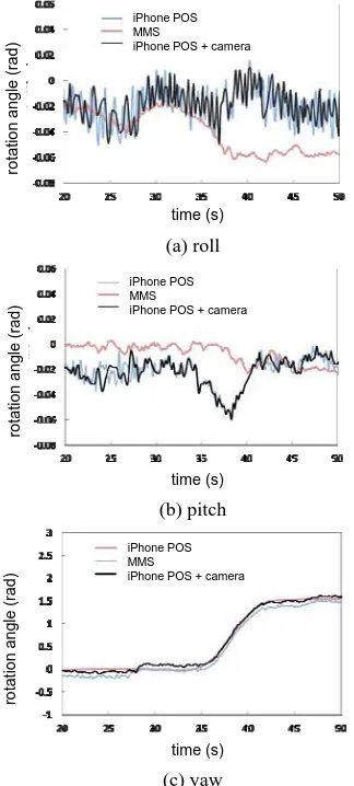
Figure 9 shows the accuracies of rotation angle by all sensors (POS and camera) integration. From the comparison between the accuracies of all sensors integration and ones of POS sensor fusion, clear improvement was not confirmed.
rot
a
ti
on ang
le
(
rad)
time (s)
iPhone POS MMS
iPhone POS + camera
(a) roll
ro
ta
ti
on
an
gle
(ra
d
)
time (s)
iPhone POS MMS
iPhone POS + camera
(b) pitch
ro
ta
ti
on an
g
le
(r
ad)
time (s)
iPhone POS MMS
iPhone POS + camera
(c) yaw
Figure 9. Result of rotation angle with all sensors integration
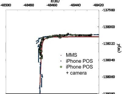
Figure 10 shows the result of all sensors integration. Compared with the previous result, the accuracy improvement can be confirmed. During the application area, the root mean square of the positions displacement with only POS sensor fusion is 3.59 (m). On the other hand, one with POS and camera integration improved to 3.26 (m).
MMS iPhone POS iPhone POS + camera
Figure 10. Result of position with all sensors integration
5. CONCLUSIONS
This paper develops the self-localization method using sensors, such as POS and cameras, on mobile devices simultaneously. The proposed method applies the Kalman filter in order to combine all sensors except for camera (POS sensor fusion). Additionally, by using the position and rotation from POS sensor fusion as initial value of bundle adjustment, POS and camera integration method is achieved.
Through experiments with real data, the accuracy improvements of position and rotation by POS sensor fusion were confirmed. The results of final integration method improved the accuracy. It means that proposed self-localization method with POS and camera make the accuracy more sophisticated compared with only POS sensor fusion. Especially, the improvement at the area in a curve is noticeable. According to the experiments, the significance of the proposed method is confirmed.
As a further work, accuracy of three dimensional coordinates estimation of feature points will be evaluated by comparing with laser scanner data on MMS. Additionally, integrated filtering method between POS filtering and bundle adjustment will become challenging investigation. As a result, promising method can be constructed, and then more impressive visualization will be accomplished.
REFERENCES
Agrawal, M. and Konolige, K., 2006. Real-time localization in outdoor environments using stereo vision and inexpensive GPS. Proceedings of the 18th International Conference on Pattern Recognition, pp.1063-1068.
Arth, C., Wagner, D., Klopschitz, M., Irschara, A., Schmalstieg, D., 2009. Wide area localization on mobile phones. Proceedings of 8th IEEE International Symposium on Mixed and Augmented Reality, pp.73-82.
Bay, H., Ess, A., Tuytelaars, T. and Vangool, L., 2008. Speeded-up robust features (SURF). Computer Vision and Image Understanding, 110(3), pp.346-359.
Daehne, P. and Karigiannis, J., 2002. Archeoguide: system architecture of a mobile out door augmented reality system. Proceedings of 1st IEEE International Symposium on Mixed and Augmented Reality, pp. 506-514.
Fischler, M. A. and Bolles, R. C., 1981. Random sample consensus: a paradigm for model fitting with applications to image analysis and automated cartography. Communications of the ACM, 24(6), pp.381-395.
Hartley, R. and Zisserman, A., 2004. Multiple View Geometry in Computer Vision. Cambridge University Press, Cambridge.
Kourogi, M. and Kurata, T., 2005. Personal positioning based on walking locomotion analysis with self-contained sensors and wearable camera. Proceedings of IEEE/ACM International Symposium on Virtual Reality Conference, pp. 71-78.
Mclauchlan, P.F., 2000. A batch / recursive algorithm for 3D scene reconstruction. Proceedings of IEEE Computer Society Conference on Computer Vision and Pattern Recognition. pp. 2738-2743.
Reitmayr, G. and Drummond, T.W., 2005. Going out: robust model-based tracking for outdoor augmented reality. Proceedings of IEEE on Virtual Reality Conference, pp. 71-78.
Ristic, B., Arulampalam, S., Gordon, N., 2004. Beyond the Kalman Filter: Particle Filter for Tracking Applications. Artech House Publishers, Boston.
Schall, G., Wagner, D., Reitmayr, G., Taichmann, E., Wieser, M., Schmalstieg, D., Hofmann, W.B., 2009. Global pose estimation using multi-sensor fusion for outdoor augmented reality. Proceedings of 8th IEEE International Symposium on Mixed and Augmented Reality, pp.153-162.
Stewenius, H., Engels, C. and Nister, D., 2006. Recent developments on direct relative orientation. ISPRS Journal of Photogrammetry and Remote Sensing, 60, pp284-294.
Triggs, B., McLauchlan, P., Hartley, R. and Fitzgibbon, A., 2000. Bundle adjustment – a modern synthesis. In Triggs, B., Zisserman, A. and Szeliski, R. eds., Vision Algorithm: Theory and Practice, Springer-Verlag, Berlin.
Wagner, D., Schmalstieg, D., Bischof, H., 2009. Multiple target detection and tracking with guaranteed framerates on mobile phones. Proceedings of 8th IEEE International Symposium on Mixed and Augmented Reality, pp.57-64.