“SLICE
-
ITERATION”, A METHOD FOR AUTOMATIC EXTRATION OF VEHICLE
LASER POINT CLOUD
Zhanying Weia,b, , Xuexia Chena,b, Hao Maa,b, Ruofei Zhonga
a Beijing Advanced Innovation Center for Imaging Technology, Capital Normal University, Beijing 100048, PR China b Chinese Academy of Surveying and Mapping, Beijing 100830, PR China
Commission III, WG III/6
KEY WORDS: Vehicle-borne laser point cloud, Automatic extraction, Axial clustering, Slice-Iteration, Interactive editing
ABSTRACT:
In this paper a method “slicing-iteration” is proposed to realize automatic extraction of vehicle-borne laser point cloud, the main steps are as follows: (1)Confirm ground reference surface; (2)Dividing points: taking points at certain height range above reference surface, divide them by certain cell size (such as 0.1m) and record points number of every cell; (3)Forming polyline: based on the number, for every cell, axially cluster is made, then find a neighbor with most similar number and form the two-point-line, further forming a polyline;
(4)Iteration: dividing points and forming polyline can be conduct at different height range and by x/y axis, so as many features as possible can be extracted. The method can also be used in half-automatic boundary extraction. Experiments show that the method in the paper is easy to use, highly adaptive, with good extraction result.
Corresponding author ([email protected]) 1. INTRODUCTION
Mobile laser scanning system can rapidly and accurately acquire point cloud of elements and photo data of roads and surface features near roads, due to large quantity and complex data content, point cloud cannot be directly used by GIS. So automatic extraction and classification is essential for application of point cloud, through automatic extraction, roads and surrounding elements of rod-shaped, strip-shaped and plane-shaped features, such as road lamp, pole, trees, kerbs line, isolation belt, railings, wall, guide board, etc., are extracted, significantly easing pressure of interactive mapping. Currently, there are mainly 4 methods of point cloud extraction: (1) Point cloud division, followed by automatic extraction (Shi Pu, 2011). 2) Classification based on scanning line(Liu Rufei, 2017, Mahao, 2014, Yang Bisheng, 2013), i.e. by analyzing points on a same scanning line, decide spatial characteristics such as inflection point, gradient change point, boundary point, linearity etc. to classify. Typically used in extraction of road boundary, tree and pole boundary, house contour line. (3)Based on picturization of point cloud (Yang Bisheng, 2010; Wei Zheng, 2012; Yang Bisheng, 2012): point cloud is divided into separate unit according to spatial distribution, then projected to a spatial plane forming the picture, use pattern recognition technology to identify the attributes such as road lamp, etc. (4)Divide point cloud into spatial voxel, then separate and classify point cloud(AK Aijazi, 2013). Above methods each has advantages as disadvantages, some is used separately, and some are used jointly. This paper proposes a kind of “slicing-iteration” method, spatially slice vehicle-borne laser point cloud, then automatically extract features from the sliced point cloud.
2. METHOD AND REALIZATION OF SLICING-ITERATION
The title should appear centered in bold capital letters, at the top of the first page of the paper with a size of twelve (12) points and single-spacing. After one blank line, type the author(s) name(s), affiliation and mailing address (including e-mail) in upper and lower case letters, centred under the title. In the case of multi-authorship, group them by firm or organization as shown in the title of these Guidelines.
Main process of “slicing-iteration” method: determine ground reference with resolution 0.5m, fetch a certain range of point cloud based on height relative to the reference surface and project to a horizontal plane, subdivide these points into cells with resolution 0.1m and calculate density of points within every cell, then cluster and vectorize accordingly. This method will be detailed as follows.
2.1 Dete rmine ground reference
There are two methods to determine ground reference surface, the first one is to find ground points by ground filtering, then build a simple DEM from ground points. And the second is, without filtering, to directly find lowest point for every cell with resolution 0.5m and record Z value.
The first method will spend more calculation time, with advantage of eliminating subsequent calculation of extracted ground points. The second is quick but less strict. If extracted target is not element very close to ground, such as kerb line, the second method can be used absolutely.
empirically appropriate to take size of 0.3~1.0m as the resolution of cells. The size shall not be too large, because it must be ensured that terrain changes can be ignored, but also not too small, for terrain accuracy should be ensured.
For convenience purpose, the reference surface cell is called as RC.
2.2 Point cloud projection
Establish a mesh with higher resolution, such as 0.1m of cell size, then project the points above RC onto the mesh. Different mesh resolution (cell size) will decide accuracy of final features, but the size is not the smaller the better. If it is less the spacing distance of points, there will be no points in many cells. In addition, it will result a target belonging to one geometric entity is divided into several cells. The principle of the value taking is larger than ground density of point cloud, slightly smaller or equal to thickness of a wall face projecting on horizontal plane. Generally speaking, 0.05m~0.1m is an advisable cell size.
For convenience purpose,the projecting mesh cell is called PC.
The follows process is for all points above RC: Find Z value in RC and calculate relative height from PC to RC, then aiming to different target, different height range is set and conduct subsequent filtering, clustering and vectorization. For example, take 0.05m~0.2m to extract kerb line; take 0.5m~1.2m to extract the isolation belt in the middle of highway; take 0.2m~1.0m to extract steps of a shopping mall, etc.
2.3 Processing PC
Record points number of every PC, if the number is smaller, for example 1~3, the points can be removing directly avoid affecting subsequent processing. If the extracting target is kerb line but without terrain filtering, threshold of points number should be increased, which can remove surrounding ground points and highlight side points of kerb.
Axis clustering: When thickness of projecting target is larger than size of PC, the target will be divided to different cells, which would result in errors such as sawtooth or double line, etc. in subsequent vectorization. The “thickness” may result from low distance accuracy of laser points, or very small inclination of wall surface or board surface, or projecting thickness of the target itself, for example, metal isolation belt. In this paper an axial clustering method is proposed to solve this problem, simple processing is as follows:
Traversing left and right neighbors (not top and bottom or diagonal neighbors) of every PC, if points number of the neighbor is larger, then current cell will transfer its points to the neighbor and set itself null, and vice versa. Generally speaking, left-right clustering can realize extraction of most elements along road, for elements perpendicular to road, it needs top-bottom clustering, for example, traffic boards.
After clustering between PCs, mean value is calculated as ordinate (x, y) for all points in each PC.
2.4 Vectorization
That is to link PC into vector line. Algorithm is as follows: First, record points number of PC as PN (points number).
For current PC,recorded as C(i, j), if PN less than given threshold (e.g. 3) or less than some times (e.g. 5 times) of mean value of its 3*3 neighbors, then set current PC as invalid, otherwise:
Find the one with biggest PN , namely PCmax, from three neighbors C(i+1,j), C(i+1,j-1), C(i+1,j+1), that is up, up left and up right neighbors. The cell of biggest PN would be the front-linker of the current PC, and the current PC will be the rear-linker for the biggest one. Pseudo code is as follows:
struct AC
if( idx<0 || vn>ratio || vn<1.0/ratio ) // invalid case { _aca[i*ix+j].next = -1;continue; } connect each other into polylines. Furthermore, those polylines can link into longer ones under the threshold of distance between them.
2.5 Dete rmine Z coordinate
and planar element needs both top and bottom (e.g. traffic board, wall surface, etc.). Generally speaking, Maximum or minimum Z in one PC can be taken as Z of PC, then as top or bottom boundary. But laser points must not reach the edge of features, so these points need some correction and smoothing. An experience is to select the boundary which with higher confidence, then deviate a certain height, e.g. take higher points for kerb line, then it is OK to move downward a height of a kerb.
3. EXPERIMENTAL RESULTS
This paper chooses point cloud of SSW from Beijing GEO-Vision to test, with space between scanning lines 5cm or so,space between points 1.5cm or so. Research area includes urban expressway, main road and ordinary road. Extracted targets include isolation belt, guard net, bridge pier, wall surface, tree trunk, kerbs, steps, etc.
Basic extraction parameters include: RC size is 0.5m; PC size is 0.1m; Minimum points number in a PC is 4; Minimum points number in a polyline is 6; Maximum distance is 0.5m and maximum angle is 75 degree for connecting between polylines. Height range relative to RC varies for different target, and the range is not strictly limit in following test unless otherwise specified.
The following is some results of extraction.
(1)Roadside double layer isolation belt, as shown in Figure 1.
Figure 1. Roadside double layer isolation belt.
Where, (a)Point cloud of Roadside double layer isolation belt, almost without interference; (b) Point cloud and extracted vector, top view; (c) Extracted vector.
(2)Isolation belt in the middle of road,as shown in the Figure 2.
Figure 2.Isolation belt in the middle of road.
Where, (a)Pint cloud of isolation belt in the middle of road ; (b)The isolation belt is interfered by plants obviously in an enlarged view; (c)Top view, point cloud and extracted vector;
(d)Top view, extracted vector .
Because interfered by plant, more strict height range can be set for better extraction results.
(3)Roadside guard net and isolation belt, as shown in the Figure 3.
Figure 3. Guard net and isolation belt.
Where, (a)Point cloud of guard net and isolation belt; (b)Top view, extracted guard net vector; (c)Top view, point cloud and extracted isolation belt vector.
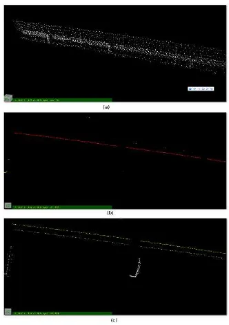
(4)Wall surface with tiny irregularity, as shown in the Figure 4.
Figure 4. Wall surface with tiny irregularity.
Where, (a)Wall point cloud; (b)Top view, point cloud and extracted contour line; (c)Wall face contour line.
In this test windows and doors can be detected by the extracted contour line, and decide their height through different height range.
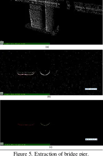
(5)Extraction of bridge pier, as shown in the Figure 5.
Figure 5. Extraction of bridge pier.
Where, (a)Point cloud of bridge pier; (b)Top view, point cloud and extracted pier vector; (c)Top view, extracted pier vector.
In this test, pier shape can be detected by extracted vector at different height, which is help to 3D modeling of pier.
(6)Vector of steps, as shown in the Figure 6.
Figure 6. Extraction of steps.
Where, (a)Step point cloud; (b)Point cloud and extracted steps vector; (c)Top view, point cloud and extracted steps vector
Because steps do not shield each other, the method in this paper is very suitable and is of very high success rate.
(7)Extraction of kerb line, as shown in the Figure 7.
Figure 7.Extraction of kerb line.
In the test, height range is very strictly limited, being 0.05~0.2. Because kerb side is not vertical surface with thickness about 0.1 of planar projection, the extracted vector basically is center line.
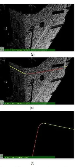
(8)Applications in mapping, as shown in the Figure 8.
Figure 8.Vector extraction in editing.
Where, (a)Point cloud of wall with arc shape; (b)Extracted wall contour line based on a certain height range; (c)Top view, extracted contour line.
4. SUMMARY AND DISCUSSION
Based on characteristics of vehicle-borne laser point cloud, in this paper, a method set of “fetching-projecting-axially clustering-vectorization” is proposed to extract features of belt-shaped agreeing to direction of vehicle moving. There are dense laser points on the sides of these spatial features, and it is a unique density in horizontal plane. Thickness error of features after horizontal projection can be reduced by axially clustering, then an algorithm of vectorization and line linking is designed. Tests demonstrate the method in this paper is of wide range of applications. In general, the method proposed is very suitable for extraction of vehicle-borne laser point cloud, and can be programed in software easily.
But the method needs to calculate or specify such parameters as ground reference, height range, size of cell to be projected, etc., which must increase the complexity of applying the method. So, we will study the plan of intelligent extraction in the future, realizing fully-automatic extraction with no-parameter (or initial parameter only). In addition, only planar coordinates (x,y) have been determined, without clearly Z coordinate, e.g., top, bottom boundary of rectangle traffic boards, wall surfaces connected together with different height, etc., this kind of extraction facing 3D modeling is also the future work.
REFERENCES
Shi Pu, J., 2011. Recognizing basic structures from mobile laser scanning data for road inventory studies. ISPRS Journal of Photogrammetry and Remote Sensing, 66(6), pp. 28-39.
LIU Rufei, J., 2017. An Automatic Extraction Method of Road from Vehicle-brone Laser Scanning Point Clouds. Geomatics and Information Science of Wuhan University, 42(2), pp. 250-256
MA Hao, J., 2014. Automatic classification and extraction of road sidelines based on vehicle-borne laser point cloud. Science of Surveying and Mapping, 39(6), pp. 126-128
Yang Bisheng, J., 2013. Semi-automated Extraction and Delineation of 3DRoads of Street Scene from Mobile Laser Scanning Point Clouds. ISPRS Journal of Photogrammetry and Remote Sensing, 79(5), pp. 80-93.
Yang Bisheng, J., 2010. A Classification-oriented Method of Feature Image Generation for Vehicle-borne Laser Scanning Point Clouds. Acta Geodaetica et Cartographica Sinica, 39(5), pp. 540-545.
Wei Zheng, J., 2012. Automated Extraction of building Facade FootPrints from Mobile LiDAR Point Clouds. Geomatics and Information Science of Wuhan University, 37(11), pp.1311-1315.
Yang Bisheng, J., 2012. Automated Extraction of Street-scene Objects from Mobile LiDAR Point Clouds. Internalional Journal of Remote Sensing, 33(18), pp. 5839-5861.