USER REQUIREMENTS SPECIFICATION AUTOMATION SYSTEM DESIGN
FOR STOPPER VALVE CHAMFERING PROCESS ON BENCH LATHE SD-32 A
MACHINE AT PT DHARMA PRECISION PARTS
Amalia Syafitri1, Rino Andias Anugraha2, and Haris Rachmat3
1,2,3Prodi S1 Teknik Industri, Fakultas Rekayasa Industri, Universitas Telkom
1[email protected], 2[email protected], 3[email protected]
Abstract
PT Dharma Precision Parts is manufacturing company that produces metal components from machining process, one of the product is stopper valve. Due to increasing in competition and demand, the company must be able to decrease the process time to fulfill the demand. The process time of existing syste m is around 9.92 seconds/part. The way that company use to decrease process time is by modifying Bench Lathe SD-32A machine which used for stopper valve chamfering process by applying automation technology. Applying automation technology in the company will get some advantages such as reducing process time, increasing production capacity and product quality. Implementation of automation system needs a good planning and consideration to function expected well and to prevent system redesign.
This research focused on User Requirement Specification (URS) design which contains a collection of information needed to design the automation systems in the industrial manufacture. URS design consists of process description, the description of the flow of electricity connected with each equipment, and control philosophy that allows the end user to understand the determined basic control system. Based on the research conducted conclude that the design of URS for stopper valve chamfering process on Bench Lathe SD-32A machine successfully implemented and the new process time is around 5 seconds/parts. The results consist of the explanation of process description, electrical diagrams, and control philosophy.
Keywords: user requirement specification, process description, electrical diagram, control philosophy
1. Introduction
Manufacturing industries have the goal to fulfill the demand by producing products productively in order to gain profit. Nowadays these objectives can be achieved by using technology such as automation technology. Most of activities done have changed from human worker into automation technology. Some company automate process in order to reduce production time, increase manufacturing flexibility, reduce costs, and eliminate h uman error (Business, 2015).
PT Dharma Precision Parts is one of the major local manufacturing companies in Indonesia that produces metal components from machining process and also supplies them to several manufacturing companies operating in Indonesia. PT Dharma Precision Parts is also a supplier for OEM (Original Equipment Manufacturer) company. PT Dharma Precision Parts has a lot of machines and a wide range of products. One of existing production processes is chamfering stopper valve components which is processed by Computer Numeric Control (CNC) machines and Bench Lathe machines. The chamfering process is begun by placing the stopper valve that has been created by a CNC machine into the spindle collet which will be locked, and the spindle collet motor will rotate. The chisel will move into the part to running the chamfering process.
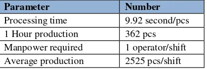
Table 1 Existing production condition
Parameter Number
Processing time 9.92 second/pcs 1 Hour production 362 pcs Manpower required 1 operator/shift Average production 2525 pcs/shift
Regarding the problems, the company needs to modify the machine used for production to quicken the production time so that the production capacity increases. By modifying the machine, the company does not need to spend a huge investment to build a new machine and consequently the machine utility increases. Design of automation technology will be applied to modify Bench Lathe SD-32A machine which used for production in the company. Automation is a technology applying mechanical, electrical, and computer systems to operate and control the operation process. Automation system design on Bench Lathe SD-32A machine needs a good planning and consideration to function expected well. According to the USA Principles, there are three steps to implement automation system. The first is knowing the existing process, the second is making the existing process simpler, and the last is implementing automation system process. As a manufacturing industry that uses automation system manufacturer must know the requirements of the automation system, so that the automation system design can be applied in accordance with the requirements or the production process. One of the methods to know the requirements of automation system is User Requirements Specification (URS) design. URS design consists of process description, the description of the flow of electricity connected with each Equipment, and control philosophy that allows the end user to understand the determined basic control system. It is concluded that User Requirements Specification (URS) design needs to be implemented in processing machine modification of Bench Lathe SD-32A machine in PT Dharma Precision Parts.
Based on this background, the problem in this research is how to design the user requirements specification (URS) automation system for stopper valve chamfering process on Bench Lathe SD-32A machine in order to decrease production process time and increase quality. The objective of this research is design the User Requirements Specification (URS) automation system for stopper valve chamfering process on Bench Lathe SD-32A machine in order to to decrease production process time and increase quality.
2. User Requirements Specification (URS) Design
This research begins from the identification phases on the research objects. Identification done by observation to the shop floor, after observation, it can be defined problems that occur in the existing system. When analyzing the existing system, do also study literature to get the appropriate research methods to solve the existing problems so that from that phase obtained the problem and method that is design the user requirements specification (URS) automation system for chamfering process on Bench Lathe SD-32A machine. The inputs will be used in this research can be seen in conceptual model. The proposed system is then tested by simulating in the simulation phase so that the proposed system can be analyzed at the analysis phase, after that will be concluded at the conclusions and suggestions phase.
Existing process time
Existing ma hining process
(chamfering)
Part specific ation
User require ment for automation
system
Existing Bench Lathe SD-32
ma chine
Process description
Hardware
specification Control philosophy
Electrical diagram
User Requirement Specifica tion Design
for Automation System
Figure 1 Conceptual model
N
User Requirement Specification (URS) used to provide a clear basis for tendering and for making a meaningful quotation. URS provide decription about the component or system needed in order to produce a product. The URS must be in a form that can be understood by a system supplier or integrator (Love, 2007). URS that can be used for articulated functionality that required by control system such as a process description, electrical diagram, and control philosophy. Process description provides a basis for the supplier to understand and interpret the user’s process objectives. The point of providing a process description is that it enables the supplier to make informed judgements about the requirements for control (Love, 2007). Electrical diagram is a graphical representation of an electrical circuit (Wikipedia.org, 2015). Electrical diagram classified into two categories, there are wiring diagram and schematic diagram. Love (2007) control philosophy is a collection of statements about policy design and principles underlying the important decisions on the control system. Control philosophy allows suppliers to understand the control system that will be used.
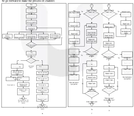
2.1 Process Description
Process description of proposed system on bench lathe SD-32A is described by a flow chart which can be seen in Figure 2 and 3. The following is proposed system scenarios for stopper valve chamfering process PT Dharma Precision Parts:
a. System preparation
This process is a process to prepare the system to be in a safe condition so that the system can run as expected. b. Inspection Process
Stopper valve inspection process from the nonconformity is the first process to be performed before the chamfering process. Stopper valve inspection process carried out in the inspection line by using the photoelectric sensor.
c. Chamfering Process
Stopper valve which has passed the inspection and were on the slider then be delivered by a linear motion to get in front of the collet. After the stopper valve was located in front of the collet then cylinder on the slider will extending push the stopper valve to attached on the collet. The next will be done to clamping stopper valve so that it will attached strongly. If stopper valve has been clamped on the collet and the system is in a safe condition, the AC motor will be active then linear motion back to the initial conditions and the drill will be go forward to make the process of chamfer.
Start A B
Stopper valve Yes Solenoid 1 active
Release
reject part? Yes Solenoid active
No
Yes
Figure 3 Proposed of new system for stopper valve chamfering process (Cont.)
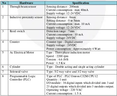
2.2 Control philosophy
Control philosophy describe the selection of hardware. Hardware specification used in proposed system:
Table 2 List of hardware and specification used in proposed system
No Hardware Specification
1 Through beam sensor Sensing distance : 200mm Current consumption : max 40mA Supply voltage: 12-24 VDC 2 Inductive proximity sensor Sensing distance : 8mm
Setting distance : 0 to 5mm Current consumption : max. 10 mA Supply voltage: 12-24 VDC
3 Reed switch Detection range : 7mm
Current consumption : 10 mA Supply voltage: 24VDC
4 Counter Counter type : Digital counter
Supply voltage : 24VDC
Power consumption : Approximately 4 Watt 5 Ac Electrical Motor Type : Three phase induction motor
Speed : 2200 rpm Torsion : 6.6 lb/ft Power : 1.5 Kw
6 Cylinder Type : Double acting and single acting cylinder
7 Solenoid valve Type: 5/2 way valve and 3/2 way valve 8 Programmable Logic
Controller (PLC)
Type of PLC : PLC Omron CJ2M CPU12 Quantity : 1 unit
I/O module : 34 digital inputs which divided into 3 and 23 digital outputs which divided into 3 modules output. Operating voltage : 220 VAC
Current consumption : 1.5 A
100% 10
0
%
1
0
0
%
8
0
%
1
0
0
%
8
0
%
8
5
%
No Hardware Specification
9 Air compressors Type : Reciprocating air compressors Power : 1.5 HP = 1119 Watt
Operating voltage : 380 VAC Current consumption : 3.7 A 10 Alarm (Buzzer) Type : Buzzer
Operating voltage : 24 VDC Current consumption : 0.02 A
11 Tower Lamp Type : Industrial tower lamp 3 module stack colors Operating voltage : 240 VAC
Current consumption : 0.19 A
12 Miniature Circuit Breaker (MCB)
Electric currents rating : 6A Voltage rating : 230 V
13 Relay Type : Omron MY2
Operating voltage : 24 V Rated current : 36.9 mA
14 Contactor Type : Magnetic contactor AC 3 Pole Rated operational power : 380 – 400 VAC Current rating : 9 A
15 Vibratory Bowl Feeder Input voltage : 220 VAC, 60 Hz Load current : 80 mA
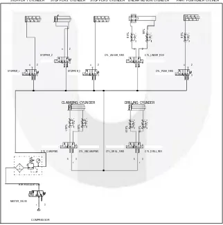
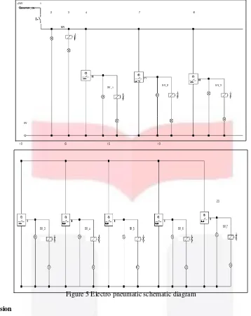
2.3 Electrical Diagram
Automation system design for chamfering process on bench lathe SD-32A is described by pneumatic schematic diagram and electro pneumatic schematic diagram to illustrate flow of electricity that are connected between equipment using Fluidsim software.
STOPPER 1 CYLINDER STOPPER 2 CYLINDER STOPPER 3 CYLINDER LINEAR MOTION CYLINDER PART POSITIONER CYLINER
4 2 4 2 STOPPER_2 CY L_LINEAR_FW D CY L_LINEAR_REV
5 3 5 3
4 2 1 4 2 1 4 2 STOPPER_1
5 3 1
STOPPER_3 5 3
1
CY L_PUSH_FW D 5 3
1
CLAMPING CYLINDER DRILLING CYLINDER
4 2 4 2 CY L_CLAMPING CY L_UNCLAMPING CY L_DRILL_FW D CY L_DRILL_REV
5 3 5 3 1 1
AIR REGULAT OR
2 MASTER_VALVE
1 3
COMPRESSOR
+24V 1
MASTER _ON
2 3 4 7 10
MV
SV_1 SV_2 SV_3
0V
10 13 16 19
23
SV_3 SV_4 SV_5 SV_6 SV_7
Figure 5 Electro pneumatic schematic diagram
3. Discussion
Existing system for stopper valve chamfering process at PT Dharma Precision Parts still using conventional system that causes long process time so production capacity cannot reach the demand and cannot achieving consistency in products quality. The way to increase the production capacity is done by implementing automated systems pneumatic technology, while maintaining quality of the product on automation system design for stopper valve chamfering process is done by inspection the product before chamfering process.
Process description have been created is the proposed new system for stopper valve chamfering process at PT Dharma Precision Parts. Explanation of the process that occurs in the stopper valve chamfering process is needed for stakeholder to know process flow at that system starting from the inspection process until chamfering process to produce the stopper valve in accordance with the specifications.
The determination of the hardware specification is necessary so that the equipment and instruments contained in the automation system for stopper valve chamfering process can run the system in accordance with its function. In addition, if the equipment does not match, it can allow the short circuit occurred on the system, the dimensions are not in accordance with the requirements of pressure, inaccuracies distance detection, and others. Determination of the hardware specifications necessary to ensure the equipment that were installed in the automation system stopper valve chamfering process can running the system in accordance with its function. In addition, if the equipment does not match, it will cause a short-circuit in the system, inaccuracies distance on the sensor detection, and others.
Selection of hardware involves several variables that need to be considered. Some of these variables is the electric power used in the process of chamfering stopper valve, the comparison between the existing condition with the hardware specifications that will be implemented, and the installation position of each hardware.
The electrical diagram design used to know the configuration of equipments that are connected with each others in the automation system for stopper valve chamfering process. By using electrical diagram stakeholders can easily determine the equipment used in the system along with the interconnection between the equipment. In the process of chamfering created of two types of electrical diagrams that is, pneumatic schematic diagram which is an
description of pneumatic systems and electro pneumatic schematic diagram which is a description of the relationship between electrical equipment and pneumatic system installed on the system.
URS automation system design successfully implemented by creating process description, control philosophy, and electrical diagram so that automation system running as expected to reducing processing time. Reducing processing time can be seen in Figure 6.
Figure 6 Processing Time of Stopper Valve Chamfering Process in Existing and Proposed System
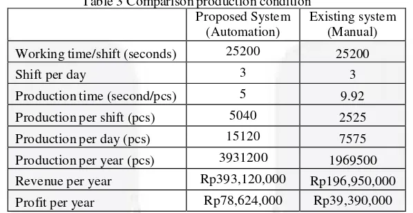
Reduction of processing time would increase production capacity so that the profit also increased. Comparison of production condition between existing and proposed system can be seen in Table 3.
Table 3 Comparison production condition Proposed System
(Automation)
Existing system (Manual) Working time/shift (seconds) 25200 25200
Shift per day 3 3
Production time (second/pcs) 5 9.92
Production per shift (pcs) 5040 2525
Production per day (pcs) 15120 7575
Production per year (pcs) 3931200 1969500 Revenue per year Rp393,120,000 Rp196,950,000
Profit per year Rp78,624,000 Rp39,390,000
Based on the calculation the proposed system gives higher profit then existing system and the pay back period can be seen in the following :
Payback period (year) = Investment/(Profit per year) Payback period (year) = 43.842.000/78.624.000 Payback period = 0.6 year
Payback period = 6.7 months
It can concluded the length of time to recover the cost of an investment to modify Bench Lathe SD -32A machine is 6.7 months.
4. Conclusion and Suggestion
4.1 Conclusion
Based on the research that have been done, it can be concluded that User Requirement Specification (URS) automation system design that consists of process description, control philosophy, and electrical diagram which used as a basis to designing automation system automation system design for stopper valve chamfering process on Bench Lathe SD-32 A machine at PT Dharma Precision Parts successfully implemented by decreasing the process time from around 9.92 seconds/part to around 5 second/part or it can said that modifying existing machine can decrease 45.5% of process time.
the equipment used in the proposed system. User Requirements Specification (URS) can be used as a basis for designing automation control system for stopper valve chamfering process on Bench Lathe SD-32A machine at PT Dharma Precision Parts.
4.2 Suggestion
The suggestions given related to this research for further purposed, that is :
1. To the next research, the design is done can noticed the cost analysis or energy consumption analysis of making selection of hardware specification.
2. To the next research, to make more detailed electrical diagram in order to describe the flow of electricity more clear.
References :
[1] Business, E. o. (2015, 1 19). Automation : Reference for business. Retrieved from Reference for Business: http://www.referenceforbusiness.com/small/A-Bo/Automation.html
[2] Croser, P., & Ebel, F. (2002). Pneumatics. Denkendorf: Festo Didactic.
[3] Groover, M. P. (2008). Automation, Production Systems, and Computer-Integrated Manufacturing. In M. P. Groover, Automation, Production Systems, and Computer-Integrated Manufacturing (p. 19). New Jersey: Pearson Prentice Hall.
[4] Groover, M. P. (2008). Automation, Production Systems, and Computer-Integrated Mnufacturing. New Jersey: Pearson Prentice Hall.
[5] Love, J. (2007). Process Automation Handbook_ A Guide to Theory and Practice. London: Springer. [6] Pratama, G. (2014). Perancangan Sistem Otomatisasi Berbasis Wireless pada Proses Penggilingan Teh
Hitam Orthodoks di PT ABC. Bandung: Telkom University.
[7] SK Gubernur Jawa Barat. (2010 - 2015). UMK Jawa Barat. Bandung: Pemerintah Jawa Barat.
[8] Wikipedia.org. (2015, 1 27). Wikipedia. Retrieved from Wikipedia: http://en.wikipedia.org/wiki/Circuit_diagram