for Adaptive Architectures and Services
Syed Asad Hussain ISBN: 0-8493-8214-9
Ad Hoc Mobile Wireless Networks: Principles, Protocols and Applications
Subir Kumar Sarkar, T.G. Basavaraju, and C. Puttamadappa
Onur Osman and Osman Nuri Ucan ISBN: 1-4200-5461-9
Context-Aware Pervasive Systems: Architectures for a New Breed of Applications
Seng Loke
ISBN: 0-8493-7255-0
Data-driven Block Ciphers for Fast Telecommunication Systems
Nikolai Moldovyan and Alexander A. Moldovyan ISBN: 1-4200-5411-2
Distributed Antenna Systems:
Open Architecture for Future Wireless Communications
Honglin Hu, Yan Zhang, and Jijun Luo ISBN: 1-4200-4288-2
Encyclopedia of Wireless and Mobile Communications
Borko Furht ISBN: 1-4200-4326-9
Handbook of Mobile Broadcasting: DVB-H, DMB, ISDB-T, AND MEDIAFLO
Borko Furht and Syed A. Ahson ISBN: 1-4200-5386-8
The Handbook of Mobile Middleware
Paolo Bellavista and Antonio Corradi ISBN: 0-8493-3833-6
The Internet of Things: From RFID to the Next-Generation Pervasive Networked Systems
Lu Yan, Yan Zhang, Laurence T. Yang, and Huansheng Ning
ISBN: 1-4200-5281-0
Technology, Services, Markets
Tony Wakefield, Dave McNally, David Bowler, and Alan Mayne
ISBN: 1-4200-4653-5
Millimeter Wave Technology in Wireless PAN, LAN, and MAN
Shao-Qiu Xiao, Ming-Tuo Zhou, and Yan Zhang ISBN: 0-8493-8227-0
Mobile WiMAX: Toward Broadband Wireless Metropolitan Area Networks
Yan Zhang and Hsiao-Hwa Chen ISBN: 0-8493-2624-9
Optical Wireless Communications: IR for Wireless Connectivity
Roberto Ramirez-Iniguez, Sevia M. Idrus, and Ziran Sun
Yan Zhang, Honglin Hu, and Masayuki Fujise ISBN: 0-8493-8036-7
Security in Wireless Mesh Networks
Yan Zhang, Jun Zheng, and Honglin Hu ISBN: 0-8493-8250-5
Wireless Ad Hoc Networking: Personal-Area, Local-Area, and the Sensory-Area Networks
Shih-Lin Wu and Yu-Chee Tseng ISBN: 0-8493-9254-3
Wireless Mesh Networking: Architectures, Protocols and Standards
Yan Zhang, Jijun Luo, and Honglin Hu ISBN: 0-8493-7399-9
AUERBACH PUBLICATIONS www.auerbach-publications.com To Order Call: 1-800-272-7737 • Fax: 1-800-374-3401
Network Design
for IP Convergence
Boca Raton, FL 33487-2742
© 2009 by Taylor & Francis Group, LLC
Auerbach is an imprint of Taylor & Francis Group, an Informa business
No claim to original U.S. Government works
Printed in the United States of America on acid-free paper 10 9 8 7 6 5 4 3 2 1
International Standard Book Number-13: 978-1-4200-6750-7 (Hardcover)
This book contains information obtained from authentic and highly regarded sources. Reasonable efforts have been made to publish reliable data and information, but the author and publisher can-not assume responsibility for the validity of all materials or the consequences of their use. The authors and publishers have attempted to trace the copyright holders of all material reproduced in this publication and apologize to copyright holders if permission to publish in this form has not been obtained. If any copyright material has not been acknowledged please write and let us know so we may rectify in any future reprint.
Except as permitted under U.S. Copyright Law, no part of this book may be reprinted, reproduced, transmitted, or utilized in any form by any electronic, mechanical, or other means, now known or hereafter invented, including photocopying, microfilming, and recording, or in any information storage or retrieval system, without written permission from the publishers.
For permission to photocopy or use material electronically from this work, please access www.copy-right.com (http://www.copywww.copy-right.com/) or contact the Copyright Clearance Center, Inc. (CCC), 222 Rosewood Drive, Danvers, MA 01923, 978-750-8400. CCC is a not-for-profit organization that pro-vides licenses and registration for a variety of users. For organizations that have been granted a photocopy license by the CCC, a separate system of payment has been arranged.
Trademark Notice: Product or corporate names may be trademarks or registered trademarks, and are used only for identification and explanation without intent to infringe.
Library of Congress Cataloging-in-Publication Data
Donoso, Yezid.
Network design for IP convergence / Yezid Donoso. p. cm.
Includes bibliographical references and index. ISBN 978-1-4200-6750-7 (alk. paper)
1. Computer network architectures. 2. Convergence (Telecommunication) 3. TCP/IP (Computer network protocol) I. Donoso, Yezid. II. Title.
TK5105.52.D66 2009
004.6’5--dc22 2008043273
Visit the Taylor & Francis Web site at http://www.taylorandfrancis.com
and the Auerbach Web site at
vii
Preface ...xi
About the Author ... xiii
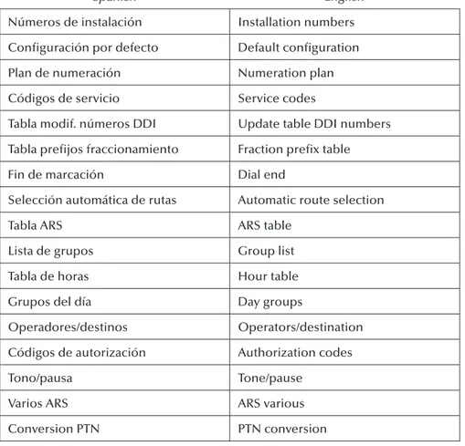
List of Translations ...xv
1
Computer Network Concepts ...11.1 Digital versus Analog Transmission ...1
1.2 Computer Networks According to Size ...7
1.2.1 Personal Area Networks (PANs) ...7
1.2.2 Local Area Networks (LANs) ...7
1.2.3 Metropolitan Area Networks (MANs) ...8
1.2.4 Wide Area Networks (WANs) ...10
1.3 Network Architectures and Technologies ...11
1.3.1 OSI ...11
1.3.2 PAN ...13
1.3.2.1 Bluetooth ...13
1.3.3 LAN ...15
1.3.3.1 Ethernet ...15
1.3.3.2 WiFi ...15
1.3.4 MAN/WAN ...16
1.3.4.1 TDM (T1, T3, E1, E3, SONET, SDH) ...16
1.3.4.2 xDSL ...18
1.3.4.3 WDM (DWDM) ...19
1.3.4.4 PPP/HDLC ...20
1.3.4.5 Frame Relay ...20
1.3.4.6 ATM ...21
1.3.4.7 WiMAX ...22
1.3.4.8 GMPLS ...23
1.3.5 TCP/IP ...24
1.4 Network Functions ...25
1.4.2 Switching ...26
1.4.3 Routing ...35
1.4.4 Multiplexing ...41
1.5 Network Equipments ...43
1.5.1 Hub ...43
1.5.2 Access Point ...45
1.5.3 Switch ...47
1.5.4 Bridge ...61
1.5.5 Router...63
1.5.6 Multiplexer ... 64
2
LAN Network Design ...672.1 Ethernet Solution ...67
2.1.1 Edge Connectivity ... 77
2.1.2 Core Connectivity ...83
2.2 WiFi Solution ...85
2.3 LAN Solution with IP ...88
2.4 VLAN Design and LAN Routing with IP ...94
2.5 LAN-MAN Connection ...113
3
MAN/WAN Network Design ...1253.1 Last-Mile Solution ...125
3.1.1 LAN Extended ...126
3.1.2 Clear Channel ...128
3.1.3 ADSL ...134
3.1.4 Frame Relay ...142
3.1.5 WiMAX ...148
3.1.6 Ethernet Access ...153
3.2 MAN/WAN Core Solution ...154
3.2.1 ATM (SONET/SDH) ...156
3.2.1.1 Digital Signal Synchronization ...156
3.2.1.2 Basic SONET Signal ...157
3.2.1.3 SONET Characteristics ...157
3.2.1.4 SONET Layers ...158
3.2.1.5 Signals Hierarchy...159
3.2.1.6 Physical Elements of SONET ...159
3.2.1.7 Network Topologies ...160
3.2.1.8 SONET Benefits ...160
3.2.1.9 SONET Standards ...161
3.2.1.10 Synchronous Digital Hierarchy (SDH) ...161
3.2.1.11 Elements of Synchronous Transmission ...165
3.2.1.12 Types of Connections ...166
3.2.1.14 Configuration of an SDH Network ...167
3.2.2 Metro Ethernet ...171
3.2.3 DWDM ...171
3.3 GMPLS ...175
3.3.1 MPLS Packet Fields ...177
3.3.1.1 Characteristics ...177
3.3.1.2 Components ...177
3.3.1.3 Operation ...179
3.4 MAN/WAN Solution with IP ...180
4
Quality of Service ...1854.1 LAN Solution ...189
4.1.1 VLAN Priority ...190
4.1.2 IEEE 802.1p ...195
4.2 MAN/WAN Solution ...195
4.2.1 QoS in Frame Relay ...196
4.2.2 QoS in ATM ...201
4.3.3 Traffic Conditioners...221
4.3.4 Bandwidth Brokers (BBs) ... 222
4.4 QoS in Layer 4 (TCP/UDP Port) ... 222
4.5 QoS in Layer 7 (Application) ...227
4.6 Network Design with Bandwidth Manager ...229
5
Computer Network Applications ...2355.1 Not Real-Time Applications ...235
5.1.1 HTTP ...236
5.1.2 FTP ...238
5.1.3 SMTP and (POP3/IMAP) ...239
5.2 Real-Time Applications ...241
5.2.1 VoIP ...241
5.2.1.1 IP-PBX ...242
5.2.1.2 Cellular IP ...250
5.2.2 IPTV ... 264
5.2.3 Videoconference ... 266
5.2.4 Video Streaming ... 268
xi
The need to integrate services under a single network infrastructure in the Internet
is increasingly evident. The foregoing is what has been defined as convergence of
services, which has been widely explained for many years. However, in practice, implementation of convergence has not been easy due to multiple factors, among
them the integration of different layer 1 and layer 2 platforms and the integration
of different ways of implementing the concepts of quality of service (QoS) under
these technological platforms.
It is precisely for the abovementioned reasons that this book was written; it aims to provide readers with a comprehensive, global vision of service convergence and especially of IP networks. We say this vision is “global” because it addresses different layers of the reference models and different technological platforms in
order to integrate them as occurs in the real world of carrier networks. This book
is comprehensive because it explains designs, equipment, addressing, QoS policies, and integration of services, among other subjects, to understand why a specific layer
or a technology may cause a critical service to not operate correctly.
This book addresses the appropriate designs for traditional and critical services
in LAN networks and in carrier networks, whether MAN or WAN. Once the appropriate design for these networks under the existing different technological
platforms has been explained in detail, we also explain under the multilayer scheme the concepts and applicability of the QoS parameters. Finally, once infrastructure has been covered, we explain integration of the services, in “not real time” and “real time,” to show that they can coexist under the same IP network.
The book’s structure is as follows:
Chapter 1—In Chapter 1 we explain some basic concepts of networks, the layer in which some of the most representative technologies are operating, and operation of some basic network equipment.
Chapter 2—This chapter concentrates on the specification of a design that’s
appropriate for a LAN network in which converged services are desired.
Chapter 3—Chapter 3 specifies a design that is appropriate both in the
Chapter 4—Chapter 4 introduces the different QoS schemes under different
platforms and explains how to specify them for critical services in order to success-fully execute service convergence.
xiii
Yezid Donoso, PhD, is currently a professor of computer networks in the Computing and System Engineering Department at the Universidad de los Andes in Bogotá, Colombia. He is a consultant in computer network and optimization for Colombian industries. He has a degree in system and computer engineering from the Universidad del Norte (Barranquilla, Colombia, 1996), an MSc degree in system and computer engineering from the Universidad de los Andes (Bogotá, Colombia, 1998), a DEA in information technology from Girona University (Girona, Spain, 2002), and a PhD (cum laude) in information technology from Girona University (Girona, Spain, 2005). He is a senior member of IEEE and a distinguished
visit-ing professor. His biography is published in the followvisit-ing books: Who’s Who in
the World, 2006 edition; Who’s Who in Science and Engineering by Marquis Who’s
Who in the World; and 2000 Outstanding Intellectuals of the 21st Century by the
International Biographical Centre, Cambridge, England, 2006. He received the title Distinguished Professor from the Universidad del Norte (Colombia, October 2004) and a National Award of Operations from the Colombian Society of Operations
Research (2004). He is the co-author of the book Multi-Objective Optimization in
xv
Spanish English
Número de canales de enlaces de VoIP
Number of VoIP channels
Número de canales de abonados de VoIP
Number of VoIP trunking
Calidad de servicio IP IP quality of service
Extensión Extension
Plan numeración Pal Main numeration plan
Plan de numeración público Public numeration plan Plan de numeración privado Private numeration plan Plan de numeración público
restringido
Restricted public numeration plan
Añadir Add
Borrar Delete
Modificar Update
Cancelar Cancel
Placa IP IP values
Placas Values
Direcciones IP para PPP IP address for PPP
CPU principal Main CPU
Acceso internet Internet access
Spanish English Dirección de router por defecto Default gateway address
Máscara subred IP IP subset mask
Ayuda Help
Direccion IP IP address
Nombre gateway VoIP VoIP gateway name
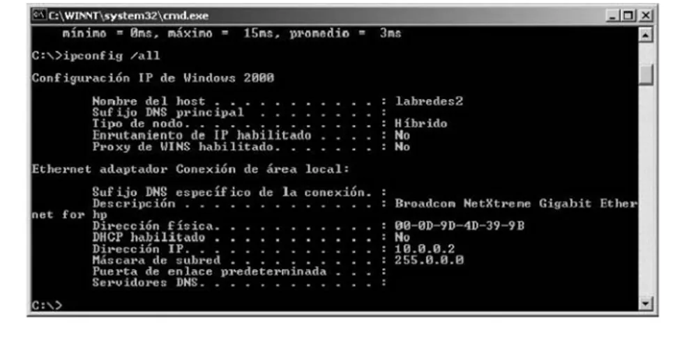
Configuración IP de Windows 2000 Windows 2000 IP configuration
Nombre del host Host name
Sufijo DNS principal Main DNS suffix
Tipo de nodo Node type
Enrutamiento de IP habilitado IP routing active
Proxy de wins habilitado Wins proxy active
Ethernet adaptador conexión de área local
Ethernet adapter local area connection
Descripción Description
Dirección física Hardware address
Mascara de subred Subnet mask
Puerta de enlace predeterminada Default gateway
Servidores DNS DNS servers
Fichero de datos Date file
Cliente Client
Tabla ARS ARS table
Inicio Start
Herramientas Tools
Proveedor Provider
Instalación típica Typical installation
Modificación tipica Typical update
Spanish English
Números de instalación Installation numbers
Configuración por defecto Default configuration
Plan de numeración Numeration plan
Códigos de servicio Service codes
Tabla modif. números DDI Update table DDI numbers
Tabla prefijos fraccionamiento Fraction prefix table
Fin de marcación Dial end
Selección automática de rutas Automatic route selection
Tabla ARS ARS table
Lista de grupos Group list
Tabla de horas Hour table
Grupos del día Day groups
Operadores/destinos Operators/destination
Códigos de autorización Authorization codes
Tono/pausa Tone/pause
Varios ARS ARS various
1
Computer Network
Concepts
This book addresses network design and convergence of IP services. In this first
chapter, we present a basic analysis of computer network fundamentals. For more in-depth information on these topics, we recommend reading [KUR07], among others.
In this first chapter we present fundamentals on the main difference between
digital transmission and analog transmission, network classification according to
size, some network architectures and technologies, and basic functions that take
place in computer networks; last, we explain the operation of the different devices
with which network design will subsequently take place.
1.1 Digital versus Analog Transmission
When transmitting over a computer network one can identify two concepts. The
first concept is the nature of the data, and the second is the nature of the signal over
which such data will be transmitted.
The nature of data can be analog or digital.
An example of digital data is a text file forwarded through a PC. The characters
of this file are coded, for example, through the ASCII code, and converted to binary
values (1s and 0s) called bits, which illustrate said ASCII character (Figure 1.1). The
same would happen for a binary file (.doc, .xls, .jpg, etc.), in which binary value
illustrates part of the information found in the file, whether through a text
An example of analog data is transmitted voice or video. In voice the informa-tion is analog; here we produce sound, where its tones are represented as continuous
waves over time and do not display discrete specific values, as happens with digital
data. Figure 1.2 shows the transmission of analog data of a person using the phone.
The nature of the signal can also be analog or digital.
An example of digital signals is transmission of information from a PC to the computer network (Figure 1.3). Here, the PC produces digital information (con-sisting of a series of 1s and 0s called bits) that will be transmitted over the data net-work also as 1s and 0s. This does not mean that a direct relationship exists between
the physical way in which the PC transmits a 1 and how the computer network
understands a 1; in other words, there are different kinds of coding schemes to
A
Character
41 ASCII HEX
ASCII BIN 01000001
Figure 1.1 Digital data.
represent bits and these can vary from PC to network and even between different
network technologies. For example, in transmissions over copper wires there are network technologies that understand a 1 as a high-voltage (+5 V) level and other technologies may understand the 1 as –5 V. It is important, therefore, to correctly interconnect the physical transmission of these technologies so that when a trans-mitting device forwards a bit as 1 and +5 V, the receiver understands that +5 V means a 1 at the bit level.
An analog signal is data or information transmitted as a continuous signal regardless of the nature of the data. Figure 1.4 shows that a PC is transmitting digital data over analog signals.
We have seen that to transmit information one can use digital or analog
sig-nals. The question now is how to represent an analog signal and how to represent
a digital signal.
1
0.8
0.6 0.4
0.2 0
–0.2 –0.4
–0.6 –0.8
* *
1 0 1 0 1 0 1
–1
0 0.5 1 1.5 2 2.5 3 3.5 4
Figure 1.4 Analog signals.
1 0 1 0 1 0 1
*
*
1 0 1 0 1 0 1
The main characteristic of analog signals is their continuous form with small
changes in the value of the function. Analog signals can be represented through Fourier series, and in this case every analog transmission could be represented by a combination of sinusoidal or cosinusoidal functions. In this case we could say that we have a function that can be described in the following way:
s t( ) sin(= 2πft)
Here we can say that the value of the signal in the time (t) domain depends on the
frequency (f) being used; we would thus be illustrating an analog signal, which is
continuous in time. To show an example, we could say that T = 1 where T = 1 / f
and realizing t from 0 to 2 with 0.01 increments; this 0.01 value has been randomly
selected for this example and any real value could be used to better represent the curve of the function. Figure 1.5 shows the signal’s behavior for these example
values. We can see in this figure that the behavior is that of a continuous signal
through which we could represent some kind of data.
We could combine a set of sinusoidal functions in such a way that the
frequen-cies used are in the range from 1 to ∞ and using odd values. The odd values of
the sin function are used so that they don’t counteract the values of the function.
We could also make every signal generated by a frequency (f) let a multiple of
1.5
1
0.5
0
s(t)
t –0.5
–1
–1.5
0 0.2 0.4 0.6 0.8 1 1.2 1.4 1.6 1.8 2
the fundamental, that is, of (1f); and also that the value of s(t), the signal as we
increase the frequency, (kf), be smaller every time due to the factor K inside the
Sin function.
The following equation could describe this.
s t kft
k
k k odd n
( ) sin( )
, =
=
∑
4 2
1 π
π
One can see that every new signal generated by a frequency (kf) multiple of the
fundamental (1f) generates an oscillation within the fundamental frequency. Since
the value of the oscillation within the total is also being divided by k, this means
that as the number of frequencies (k) increases, its incidence over the value of the resulting signal [s(t)] is increasingly smaller.
The following scenarios result from the foregoing equation by changing the
value of k, that is, the number of frequencies used.
For all cases T = 1. We will begin by showing the effect when n = 1 (Figure 1.6),
that is, when we only have frequency 1f. In this case the signal is similar to Figure 1.5.
1.5
1
0.5
0
s(t)
t –0.5
–1
–1.5
0 0.2 0.4 0.6 0.8 1 1.2 1.4 1.6 1.8 2
In this new case we show the effect when n = 3 (Figure 1.7). In other words,
we have frequencies 1f and 3f. The resulting effect is that the signal generated by
3f superimposes the signal generated by 1f, with the additional behavior that the
most influential signal over the value of s(t) is 1f, since the oscillation of 3f is much
smaller (one-third) than that of 1f.
The next example shows the resulting signal behavior [s(t)] when n = 5
(Figure 1.8). It is evident in this figure that there are more oscillations (3f and 5f)
in terms of the fundamental frequency (1f).
We could successively continue trying with different values of n and every
time we will find more oscillations in terms of the fundamental frequency (1f).
For example, if we have n = 19 (Figure 1.9), the signal will increasingly look more
like a digital style signal. The important thing is that the electronic device can
understand during the time of a bit if the value is, for example, in this case, +1 or –1. We can conclude from the foregoing that more or fewer frequencies are used to represent a digital signal.
Finally, if we use n = 299 (Figure 1.10) in this example we see a good representa-tion of a digital signal, which in this case has only two values, +1 or –1. The example
that we have used does not intend to tell us that electronic devices must necessarily use this range of frequencies; it has been used for educational purposes.
1.5
1
0.5
0
s(t)
t –0.5
–1
–1.5
0 0.2 0.4 0.6 0.8 1 1.2 1.4 1.6 1.8 2
1.2 Computer Networks According to Size
Computer networks may be classified in several ways according to the context of
the study being conducted. The following is a classification by size. Later on we will
specify to which of the networks we will apply the concepts of this book.
1.2.1 Personal Area Networks (PANs)
Personal Area Networks are small home computer networks. They generally
con-nect home computers to share other devices such as printers, stereo equipment, etc. Technologies such as Bluetooth are included in PAN networks.
A typical example of a PAN network is a connection to the Internet through the cellular network. Here, the PC is connected via Bluetooth to the cell phone, and through this cell phone we connect to the Internet, as illustrated in Figure 1.11.
1.2.2 Local Area Networks (LANs)
Local Area Networks are the networks that generally connect businesses, public institutions, libraries, universities, etc., to share services and resources such as the
1.5
1
0.5
0
s(t)
t –0.5
–1
–1.5
0 0.2 0.4 0.6 0.8 1 1.2 1.4 1.6 1.8 2
Internet, databases, printers, etc. They include technologies such as Ethernet (in any
of its speeds, today reaching up to 10 Gbps), Token Ring, 100VG-AnyLAN, etc.
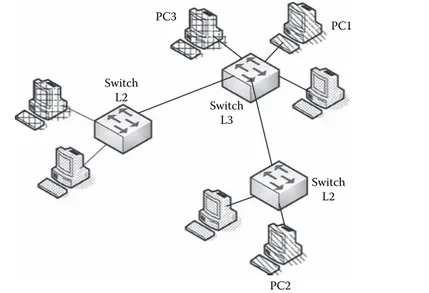
The main structure of a LAN network traditionally consists of a switch to which
the switches of office PCs are connected. Corporate servers and other main
equip-ment are also connected to the main switch. Traditionally, this main switch, which can be a third layer switch or through a router connected to the main switch, is
the one that connects the LAN network to the Internet. This connection from the
LAN network to the carrier or ISP is called the last mile. Figure 1.12 shows a traditional LAN network design.
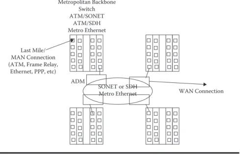
1.2.3 Metropolitan Area Networks (MANs)
Metropolitan Area Networks are networks that cover the geographical area of a city, interconnecting, for instance, different offices of an organization that are within
the perimeter of the same city. Within these networks one finds technologies such
as ATM, Frame Relay, and xDSL, cable modem, RDSI, and even Ethernet.
A MAN network can be used to connect different LAN networks, whether
with each other or with a WAN such as Internet. LAN networks connect to MAN networks with what is called the last mile through technologies such as ATM/ SDH, ATM/SONET, Frame Relay/xDSL, ATM/T1, ATM/E1, Frame Relay/T1,
1.5
1
0.5
0
s(t)
t –0.5
–1
–1.5
0 0.2 0.4 0.6 0.8 1 1.2 1.4 1.6 1.8 2
Frame Relay/E1, ATM/ADSL, Ethernet, etc. Traditionally, the metropolitan core is made up of high-velocity switches, such as ATM switchboards over an SDH
ring or SONET or Metro Ethernet. The new technological platforms establish that
MAN or WAN rings can work over DWDM and can go from the current 10 Gbps
to transmission velocities of 1.3 Tbps or higher. These high-velocity switches can
also be layer 3 equipments and, therefore, may perform routing. Figure 1.13 shows a traditional MAN network design.
1
0.8
0.6
0.4
0.2
0
–0.2
–0.4
–0.6
–0.8
–1
0 0.2 0.4 0.6 0.8 1 1.2 1.4 1.6 1.8 2
s(t)
t
Figure 1.10 s(t) function with n = 299.
PC
Cellular Bluetooth
Cellular Network Internet
1.2.4 Wide Area Networks (WANs)
Wide Area Networks are networks that span a wide geographical area. They
typi-cally connect several local or metropolitan area networks, providing connectivity to devices located in different cities or countries. Technologies applied to these
networks are the same as those applied to MAN networks, but in this case a larger geographical area is spanned, and, therefore, a larger number of devices and greater complexity in the analysis that must be done to develop the optimization process are needed.
Core Switch (Chassis) Ethernet
Edge Switch
PCs
PCs
Servers
Last Mile/ Man Connection
Figure 1.12 LAN design.
Metropolitan Backbone Switch ATM/SONET
ATM/SDH Metro Ethernet
Last Mile/ MAN Connection (ATM, Frame Relay,
Ethernet, PPP, etc)
SONET or SDH Metro Ethernet ADM
WAN Connection
The most familiar case of WAN networks is the Internet as it connects many
networks worldwide. A WAN network design may consist of a combination of layer 2 (switches) or layer 3 (routers) equipment, and the analysis depends exclusively on the layer under consideration. Traditionally, in the case of this type of network, what’s normal is that it be analyzed under a layer 3 perspective.
Figure 1.14 shows a traditional WAN network design.
In this book we will work with several kinds of networks. Chapter 3 discusses MAN and WAN network designs.
1.3 Network Architectures and Technologies
This section presents basic concepts of some architectures such as OSI and TCP/
IP, and some models of real technologies. The purpose is to identify the functions
performed by each of the technologies as compared to the OSI reference model.
1.3.1 OSI
This model was developed by the International Organization for Standardization,
ISO, for international standardization of protocols used at various layers. The
model uses well-defined descriptive layers that specify what happens at each stage
of data processing during transmission. It is important to note that this model is not a network architecture since it does not specify the exact services and protocols that will be used in each layer.
The OSI model is a seven-layer model:
Physical layer—The physical layer is responsible for transmitting bits over a
phys-ical medium. It provides services at the data link layer, receiving the blocks the latter generates when emitting messages or providing the bits chains when receiving information. At this layer it is important to define the type of
physi-cal medium to be used, the type of interfaces between the medium and the device, and the signaling scheme.
MAN Connections
WAN Backbone Switch/Router
Data Link layer—The data link layer is responsible for transferring data between
the ends of a physical link. It must also detect errors, create blocks made up of bits, called frames, and control data flow to reduce congestion. The data link
layer must also correct problems resulting from damaged, lost, or duplicate frames. The main function of this layer is switching.
Network layer—The network layer provides the means for connecting and
deliv-ering data from one end to another. It also controls interoperability problems
between intermediate networks. The main function performed at this layer
is routing.
Transport layer—The transport layer receives data from the upper layers, divides
it into smaller units if necessary, transfers it to the network layer, and ensures that all the information arrives correctly at the other end. Connection between
two applications located in different machines takes place at this layer, for
example, customer-server connections through application logical ports. Session layer—This layer provides services when two users establish
connec-tions. Such services include dialog control, token management (prevents two sessions from trying to perform the same operation simultaneously), and synchronization.
Presentation layer—The presentation layer takes care of syntaxes and semantics
of transmitted data. It encodes and compresses messages for electronic
trans-mission. For example, one can differentiate a device that works with ASCII
coding and one that works with BCD, even though in each case the informa-tion being transmitted is identical.
Application layer—Protocols of applications commonly used in computer
net-works are defined in the application layer. Applications found in this layer
include Internet surfing applications (HTTP), file transfer (FTP), voice over
networks (VoIP), videoconferences, etc.
These seven layers are depicted in Figure 1.15.
PHYSICAL
1.3.2 PAN
PAN technologies include Bluetooth, which is described next.
1.3.2.1 Bluetooth
Bluetooth is the name of the technology specified by standard IEEE 802.15.1, whose
goal traditionally focuses on allowing short-distance communication between fixed
and mobile devices. Devices that most normally use this technology are PDAs (per-sonal digital assistants) (Figure 1.16), printers, laptops, cellular phones, and key-boards, among others.
It is somewhat complicated to write with a pencil, for instance, on a PDA. For this reason, external keyboards that connect via Bluetooth to the PDA have been created, thus avoiding the use of connecting cables. In other words, it is very
practi-cal for a PDA to have Bluetooth technology so that it can interconnect to different
external devices. The use of Bluetooth is no longer as frequent in laptops, since
laptops now feature built-in WiFi technology that enables their connection to the
Internet, among PCs, to a computer network, etc., faster and with a wider range
than with Bluetooth. The market is also seeing devices with built-in WiMAX; this
means that they connect to the Internet not only at a hot spot but anywhere in the city, even on the go, with standard IEEE 802.16e. Bluetooth, therefore, is an excel-lent technology for devices that require little transmission Mbps and short range.
In Bluetooth version 1.0 one can transmit up to 1 Mbps gross transmission rate
and an effective transmission rate of around 720 Kbps. It can reach a distance of
approximately 10 m, although it could reach a greater range with more battery use due to the power needed to reach such distances with a good transfer rate. It uses a frequency range of 2.4 GHz to 2.48 GHz. Version 1.2 improved the overlapping between Bluetooth and WiFi in the 2.4 GHz frequencies, allowing them to work continuously without interference; safety, as well as quality of transmission, was also improved. Last, version 2.0 improves the transmission rate, achieving 3 Mbps, and has certain improvements over version 1.2 that correct some failures.
When compared to OSI architecture, Bluetooth is specified in layer 1 and part
of layer 2, as shown in Figure 1.17.
The power range of antennae, from 0 dBm to 20 dBm, is defined in the RF
(radio frequency) sublayer, associated to the physical layer. The frequency is found
in the 2.4 GHz range.
The physical link between network devices connected in an ad hoc scheme,
in other words, among all without an access point, is established in the baseband sublayer, also associated to the physical layer.
Bluetooth layer 2 is formed by the link manager and the Logical Link Control and Adaptation Protocol (L2CAP), which provide the mechanisms to establish connection-oriented or nonoriented services in the link and perform part of the
functions defined in layer 2 of the OSI model.
L2CAP / Link Manager
1.3.3 LAN
There are many different types of LAN technologies: some are no longer used and
others are used more than others. In this section we discuss only two of these tech-nologies. Ethernet is the most common wired LAN solution and WiFi is the most widespread as wireless LAN.
1.3.3.1 Ethernet
Ethernet technology was defined by a group of networking companies and later
standardized by IEEE. Layer 1 of Ethernet defines the electrical or optical
charac-teristics for transmission, as well as the transmission rate. Layer 2 Ethernet consists of two IEEE standards. The first, standard 802.3, traditionally works with the
CSMA/CD (Carrier Sense Medium Access with Collision Detection) protocol to
access the medium and transmit. The second, 802.2, defines the characteristics of
transmission at the link in case it is connection oriented or nonoriented. Figure 1.18 shows the layers of Ethernet technology.
1.3.3.2 WiFi
WiFi (Wireless Fidelity) technology is a set of IEEE 802.11 standards for wireless
networks. Standard 802.11 defines the functions of both layer 1 and layer 2 in
comparison with the OSI reference model. At the physical layer, the frequency and the transmission rate depend on the standard being used. For example, standard 802.11a uses the 5 GHz range and can transmit at a range of 54 Mbps; standard 802.11b uses the 2.4 GHz range and can transmit at a rate of 11 Mbps; and stan-dard 802.11g uses the same range as 802.11b and can transmit up to 54 Mbps. A new standard currently being developed, 802.11n, is aimed at transmitting around
300 Mbps in the 2.4 GHz frequencies. This technology will reach distances of 30 m
to 100 m depending on the obstacles, the power of antennae, and the access points.
PHYSICAL
As to layer 2 of the OSI model, WiFi defines a standard to access the CSMA/CA
(Carrier Sense Medium Access with Collision Avoid) medium. Figure 1.19 shows the layers of WiFi technology.
As we have seen, when we talk about the name of LAN technologies we refer to those that perform the layer 1 and layer 2 functions as compared to the OSI model. It will therefore be necessary to go over other technologies to see how they comple-ment with regard to network interconnection and other layers of the OSI model.
1.3.4 MAN/WAN
This section analyzes the architectures of LAN network accesses to MAN or WAN
networks, commercially known as last mile or last kilometer, and the architectures
that are part of operator backbones. We will find here that some technologies define
only layer 1 functions and others only layer 2 functions.
1.3.4.1 TDM (T1, T3, E1, E3, SONET, SDH)
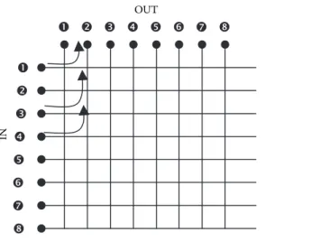
Time Division Multiplexing (TDM) technology divides the transmission line into different channels and assigns a time slot for data transfer to every channel
associ-ated with each transmitter (Figure 1.20). This resource division scheme is called
multiplexing and is associated with layer 1.
T1 lines, specifically, consist of 24 channels and their maximum transmission
rate and signaling can be calculated as follows:
Each T1 frame consists of 24 channels of 8 bits each plus 1 bit signaling per frame, and each frame leaves every 125 µs; thus, 8000 frames are generated in 1 s.
The calculation is as follows:
(24 channels × 8 bits/channel) = 192 bits/frame + 1 bit/signaling frame = 193 bits/ frame * 8000 frames/s = 1,544,000 bps = 1.5 Mbps
CSMA/CA
Such T1 lines are used in North America while in Europe the lines used are E1. In the latter case each frame consists of 32 channels of 8 bits each and every frame is generated every 125 µs.
For an E1 line the transmission rate with data and signaling is given by the fol-lowing equation:
(32 channels × 8 bits/channel) = 256 bits/frame * 8000 frames/s = 2,048,000 bps = 2.048 Mbps
In both T and E carriers there are other fairly commercial standards such as T3, with a maximum data and signaling rate of 44.736 Mbps, and E3, with a rate of
34.368 Mbps. There are other T and E specifications that are used in some
coun-tries and are complementary to the ones discussed in this book.
There are other technologies based on TDM that can achieve faster speeds,
such as Synchronous Optical Networking (SONET) used in North America and Synchronous Digital Hierarchy (SDH) used in the rest of the world. Both tech-nologies, as their name says, perform synchronous transmission between transmit-ter and receiver.
In SONET, the first carrier layer, OC-1, corresponds to a total transmission rate
of 51.84 Mbps, and in SDH STM-1 corresponds to a total transmission rate of 155
Mbps; the same transmission rate in SONET is given by carrier OC-3. The next
value in SONET is associated to OC-12, and in SDH STM-4, whose total trans-fer rate is 622 Mbps. In the case of last-mile, high-speed accesses, rates OC-3 and OC-12 would be used in SONET and STM-1 and STM-4 would be used in SDH.
The next transfer rates, OC-48/STM-16, with a rate of 2.4 Gbps, and OC-192/
STM-64, with a rate of 9.9 Gbps, belong to the backbone of MAN or WAN car-rier networks. Still, there are other standards for SONET and SDH that are not as popular as the ones just mentioned. It is also possible to transmit both SONET
PHYSICAL DATA LINK NETWORK TRANSPORT
SESSION PRESENTATION
APPLICATION
OSI TDM
T1, E1, SONET, SDH
and SDH over Wavelength Division Multiplexing (WDM), thus increasing the transmission rate. WDM is discussed in a later section.
Summarizing, the lines T1, T3, E1, E3, SONET, and SDH correspond to layer 1 of the OSI model.
1.3.4.2 xDSL
Digital Subscriber Line (DSL) technologies provide data transmission at rates higher than 1 Mbps, and their main characteristic is that they use the wires of local telephone networks. Examples of DSL technologies include HDSL High bit-rate Digital Subscriber Line (HDSL), Very high bit-bit-rate Digital Subscriber Line (VDSL), Very high bit-rate Digital Subscriber Line 2 (VDSL2), Single-pair High-speed Digital Subscriber Line (SHDSL), and Asymmetric Digital Subscriber Line (ADSL) with the newer versions ADSL2 and ADSL2+ (Figure 1.21).
Table 1.1 is a comparison table of the different DSL technologies.
Table 1.1 Comparison of DSL Technologies
Characteristic HDSL VDSL VDSL2 SHDSL ADSL ADSL2 ADSL2+
Speed
As a consequence of the foregoing speeds, DSL technologies are also used as high-speed, last-mile access solutions, but with the convenience of using the same copper lines as telephone lines. We can also say that VDSL and ADSL2+ technolo-gies are appropriate to receive services such as IPTV (Television over IP).
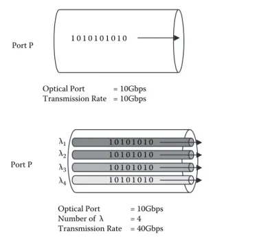
1.3.4.3 WDM (DWDM)
Just like in technologies with TDM, Dense Wavelength Division Multiplexing
(DWDM) technology multiplexes the transmission of different wavelengths over a
single optic fiber. In other words, with this multiplexing not only are 1s and 0s
car-ried at the fiber level, but the 1s and 0s are transmitted over every wavelength.
Figure 1.22a illustrates optic fiber transmission without DWDM, and
Figure 1.22b illustrates the same optic fiber transmission (provided it is
compat-ible) with DWDM.
In this case, devices are currently being developed to support up to 320 λ and
could undoubtedly continue increasing; this means that if the transmission speed of the optical port is 10 Gbps, with DWDM it would be possible to transmit
approxi-mately 3.2 Tbps. Typical devices found today are 128 or 160 λ.
SONET, SDH, and Ethernet are currently being transmitted over DWDM; for this reason, DWDM is part of layer 1. Figure 1.23 shows DWDM architecture.
1 0 1 0 1 0 1 0 1 0
Optical Port = 10Gbps Transmission Rate = 10Gbps Port P
1 0 1 0 1 0 1 0 1 0 1 0 1 0 1 0 1 0 1 0 1 0 1 0 1 0 1 0 1 0 1 0
Optical Port = 10Gbps Number of λ = 4 Transmission Rate = 40Gbps λ4
λ3 λ2 λ1
Port P
1.3.4.4 PPP/HDLC
Point to Point Protocol (PPP) and High Layer Data Link Control (HDLC) are two technologies related to layer 2 of the OSI model that perform the following func-tions, among others: establishing the communication in a point-to-point network, meaning that such technologies do not perform the switching function; retransmit-ting packages when there is a loss; recovering in case of package order synchroni-zation failure; performing encapsulation (this function will be explained in detail
in a later section); and verifying errors of transmitted bits. The foregoing means
that such technologies do not define any layer 1 characteristics and must
obvi-ously coexist with some layer 1 technologies. There are many technologies similar
to PPP and HDLC that despite having common characteristics are incompatible in function; in other words, if you have a link and connect two routers to this
link, one with HDLC configuration and the other with PPP, such routers will not
understand each other and, no matter how active the interface is in layer 2, it will not perform its function properly. Similar technologies include LLC and DLC (for LAN networks), LAP-B (2nd layer of the X.25 networks), LAP-F (for Frame Relay networks), and LAP-D (for ISDN networks), among others.
Figure 1.24 shows the architecture of HDLC and PPP. One could, for example,
transmit HDLC over HDSL lines or T1 or E1 lines. The same is true for PPP, but
in this latter case one has the POS (Packet over SONET) technology that forwards PPP over SONET.
1.3.4.5 Frame Relay
Frame Relay is a technology that operates at layer 2 of the OSI reference model and its main function includes switching, which means that to establish trans-mission between two edge points in Frame Relay one needs intermediate devices
(called switches) that decide where the packages are to be resent. This function is
called switching. Like PPP it also performs encapsulation and error control through
PHYSICAL DATA LINK
NETWORK TRANSPORT
SESSION PRESENTATION
APPLICATION
DWDM (λs) SONET, SDH, Ethernet
OSI WDM
Cyclic Redundancy Code (CRC). Frame Relay does not define layer 1 although at
a certain point Integrated Services Digital Network (ISDN) lines had been
speci-fied as this layer’s solution, but later platforms such as HDSL, line T1, and line E1,
among others, were specified.
Figure 1.25 shows the architecture of Frame Relay, which could, for instance, be transmitted over HDSL lines or T1 or E1 lines.
1.3.4.6 ATM
Asynchronous Transfer Mode (ATM) is a network technology that uses the con-cepts of cell relay and circuit switching and that specifies layer 2 functions of the
OSI reference model. What cell relay accomplishes is that the new volume of data to be transferred, called cell, has a fixed size, contrary to packages, in which size
is variable. ATM cells are 53 bits, of which 48 are data and five are ATM
head-ers. In addition, cell relay technology performs connection-oriented communica-tions and its work scheme is unreliable because the cells are not retransmitted. This
PHYSICAL
HDSL, T1, E1, SONET (POS) HDLC/PPP
OSI HDLC/PPP
Figure 1.24 PPP/HDLC architecture.
PHYSICAL
OSI Frame RelayFrame Relay
HDSL, T1, E1, ISDN HDSL, T1, E1, ISDN
Frame Relay Frame Relay
technology assumes that if the information is lost and needs to be retransmitted, a higher layer will take care of it.
Now all higher layer technologies are specified to work with packages. For this
reason it was necessary to specify a sublayer in ATM that will take a package and will fragment it into smaller units in order to construct cells. Similarly, it is neces-sary to perform the inverse function; that is, when the receiver receives a number of cells, this sublayer must be capable of reconstructing the source package relative to various ATM cells. Another function that must be performed is convergence of
ser-vices: data, voice, and video convergence was specified in ATM networks, hence it
was necessary to establish a function that would identify the different services and
integrate them into a single transmission network. All of the functions discussed in
this paragraph are performed by a sublayer called ATM Adaptation Layer (AAL).
Figure 1.26 shows the architecture for ATM and AAL and, for example, could transmit over HDSL, SONET, SDH, and ADSL, among others.
1.3.4.7 WiMAX
WiMAX technology, whose specification is given by standard IEEE 802.16 and
whose solutions span a MAN network, is currently penetrating the markets and there are still uncertainties about its being able to meet the expectations that have risen around it.
Standard IEEE 802.16 in general defines both layer 1 and layer 2 according
to the specifications of the OSI reference model. In layer 1 it specifies the type of
coding to be used, and here we can mention QPSK, QAM-16, and QAM-64, and defines the time slots through TDM. In layer 2 it specifies three different sublayers:
security sublayer, access to the medium sublayer, and convergence of specific
ser-vices to layer 2 sublayer. In the latter case one can define different types of services
and, last, at this layer it defines the frame structure (Figure 1.27).
ATM PHYSICAL
DATA LINK NETWORK TRANSPORT
SESSION PRESENTATION
APPLICATION
HDSL, SONET, SDH, ADSL
OSI ATM
AAL
1.3.4.8 GMPLS
Multiprotocol Label Switching (MPLS) is a data-carrying technology located between layer 2 (link) and layer 3 (network), according to the OSI reference model, that was designed to integrate traffic of the different types of services such as voice,
video, and data (Figure 1.28). It was also designed to integrate different types of
transportation networks such as circuits and packages and, consequently, to homog-enize layer 3 (IP) with layer 2 (Ethernet, WiFi, ATM, Frame Relay, WiMAX, PPP,
and HDLC, among others). Through this technology it seems as if IP were
connec-tion oriented by means of the creaconnec-tion of the Label Switched Paths (LSPs).
What Generalized Multiprotocol Label Switching (GMPLS) does is expand the
control plane concept of MPLS to cover what is defined in MPLS such as SONET/
SDH, ATM, Frame Relay, and Ethernet and, in addition to supporting the pack-age commutation technologies, also support time-based multiplexing (TDM) or
commutation based on wavelength (λ) or ports or fibers. In this sense, the GMPLS
control plane would encompass platforms of both layer 2 and layer 1 (Figure 1.29).
Security and Access
Figure 1.27 WiMAX architecture.
ATM/ETH/FR/PPP/…
Hence, we can locate GMPLS vertically covering part of layer 2 and part of layer 1, depending upon which platform to which it would be applied.
1.3.5 TCP/IP
The set of TCP/IP protocols allows communication between different machines
that execute completely different operating systems. It was developed mainly to
solve interoperatibility problems between heterogeneous networks, allowing that hosts need not know the characteristics of intermediate networks.
The following is a description of the four layers of the TCP/IP model.
Network Interface Layer—The network interface layer connects equipment to
the local network hardware, connects with the physical medium, and uses a specific protocol to access the medium. This layer performs all the functions
of the first two layers in the OSI model.
Internet Layer—This is a service of datagrams without connection. Based on a
met-rics the Internet layer establishes the routes that the data will take. This layer
uses IP addresses to locate equipment on the network. It depends on the routers, which resend the packets over a specific interface depending on the IP address of
the destination equipment. It is equivalent to layer 3 of the OSI model.
Transportation Layer—The transportation layer is based on two protocols. User
Datagram Protocol (UDP) is a protocol that is not connection oriented: it provides nonreliable datagram services (there is no end-to-end detection or correction of errors), does not retransmit any data that has not been received, and requires little overcharge. For example, this protocol is used for real-time audio and video transmission, where it is not possible to perform retransmis-sions due to the strict delay requirements of these cases. Transmission Control Protocol (TCP) is a connection-oriented protocol that provides reliable data transmission, guarantees exact and orderly data transfer, retransmits data that
ATM/ETH/FR/PPP/…
has not been received, and provides guarantees against data duplication. TCP does the task of layer 4 in the OSI model. All applications working under this protocol require a value called port, which identifies an application in an
entity, and through which value the connection is made with another appli-cation in another entity. TCP supports many of the most popular Internet applications including HTTP, SMTP, FTP, and SSH.
Application Layer—The application layer is similar to the OSI application layer,
serving as a communication interface and providing specific application
services. There are many protocols on this layer, among them FTP, HTTP,
IMAP, IRC, NFS, NNTP, NTP, POP3, SMTP, SNMP, SSH, Telnet, etc. Figure 1.30 illustrates the TCP/IP model and its layers.
1.4 Network Functions
This section provides an introduction to fundamentals of some of the main
func-tions performed during data network transmission. Among these funcfunc-tions we mention encapsulation, switching, and routing.
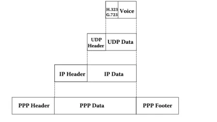
1.4.1 Encapsulation
This function consists of introducing data from a higher layer (according to the
OSI model) in a lower layer, for example, if an IP package is going to be transferred through a PPP link. Figures 1.24 and 1.30 show that PPP is in layer 2 and IP is in layer 3; therefore, PPP would encapsulate the IP package. Figure 1.31 shows an example of encapsulation.
Figure 1.32 demonstrates the encapsulations from the application layer through to the link layer if we analyze the complete encapsulation process for transmission of a voice package via VoIP in such a PPP channel.
PHYSICAL
1.4.2 Switching
The switching function is performed by certain devices when making the
deci-sion—given an entry frame with a switching value that can be a label in MPLS,
a Data Link Control Identifier (DLCI) in Frame Relay, a Virtual Path Identifier
(VPI)/Virtual Channel Identifier (VCI) in ATM, a Medium Access Control (MAC)
address in Ethernet, or a λ in Optical Lambda Switching (OLS)/Optical Circuit
Switching (OCS)—of which switching value to use, in case the specific technology
allows it, and through which physical outlet port such a frame should exit.
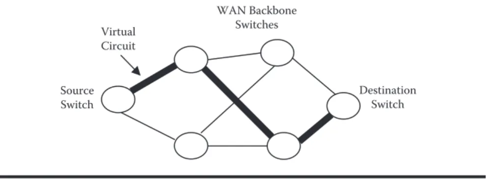
To perform switching, technologies such as Frame Relay and ATM, among
others, a virtual circuit must first be established that communicates two external
switches through a complete network of switches. Such virtual circuits may be cre-ated in two ways: Permanent Virtual Circuit (PVC) or Switched Virtual Circuit (SVC). One characteristic of PVCs is that such virtual circuits are always estab-lished, whether or not there is data transmission. SVCs, on the other hand, are established while data transmission is taking place. Figure 1.33 shows the concept of virtual circuit, which follows an established path through several switches in the network. In this case it is possible to use several routes, but only one of them has been selected as the transmission route through the virtual circuit.
IP Data
IP Data
PPP Data
PPP Data
PPP Header
PPP Header PPP FooterPPP Footer
IP Header
Figure 1.32 Complete encapsulation via VoIP.
IP Data
IP Data
PPP Data
PPP Data
PPP Header
PPP Header PPP FooterPPP Footer
IP Header
IP Header
In Frame Relay, switching takes place through the DLCI value, which is
con-figured along a virtual circuit. A switching scheme in a Frame Relay network is
shown in Figure 1.34. In this example it is possible to transmit information from PC1 to PC2 or from PC2 to PC1 in their respective LAN networks, which are connected through a MAN or WAN network in Frame Relay. To exemplify this case, assume that right now PC1 wants to transmit a package (which can be IP in layer 3) to PC2. PC1 will forward an Ethernet frame placing its own address (PC1) as source MAC address and the MAC address of router R1 as destination MAC address. Based on the destination IP address (this will be explained in more detail in Chapter 3) associated to the PC2 device, router R1 will perform its routing func-tion and decide to forward the package through the last-mile connecfunc-tion. Since the last-mile connection is in Frame Relay, R1 will perform the encapsulation in Frame Relay placing 20 as the DLCI value. Such DLCI values are assigned by the carrier.
This frame will follow the logical path marked by the virtual circuit. Next, the
frame with DLCI 20 will arrive at the Frame Relay switch of carrier SW1 through
the last mile via port P1. Then, SW1 through its switching table will perform the
switching function, changing value DLCI 20 for value DLCI 21 (as indicated in SW1’s switching table), and forward out the frame via port P2. Following the logi-cal path of the virtual circuit, the frame will come in at SW2 via port P1, where switching will take place again from DLCI 21 to 22, and will be resent out via port P2. Subsequently, SW3 will receive the frame with a value of DLCI 22 and reforward it via port P2 with value DLCI 23 until it finally reaches its destination
network through the last mile with router R2. Router R2 will perform its routing function, which will be explained later, to remove the layer 2 Frame Relay header and will replace it with an Ethernet header with the Ethernet destination MAC address of PC2 for delivery thereto.
In ATM, switching takes place through values VPI and VCI, which are
con-figured along a virtual circuit. Figure 1.35 shows switching in an ATM network.
In this case it is possible to transmit data from PC1 toward PC2 or from PC2 toward PC1 in their respective LAN networks, which are connected through a MAN or WAN network in ATM. To exemplify this case, assume that right now
WAN Backbone
N
C
PC1 wants to transmit a package (which can be IP in layer 3) to PC2. PC1 will forward a frame placing its own address (PC1) as Source MAC address and the MAC address of router R1 as destination MAC address. Based on the destination IP address (this will be explained in more detail in Chapter 3) associated to device PC2, router R1 will perform its routing function and decide to forward the pack-age through the last-mile connection. Since the last-mile connection is in ATM, R1 will perform the encapsulation in ATM and construct cells assigning VPI/VCI 1/2. Such VPI/VCI values are assigned by the carrier. Said cell will follow the logi-cal path marked by the virtual circuit. Next, the cell with VPI/VCI 1/2 will arrive
at the ATM switch of carrier SW1 through the last mile via port P1. Then, SW1
through its switching table will switch the values VPI/VCI 1/2 for values VPI/VCI 1/3 (as indicated in SW1’s switching table), and forward out the frame via port P2. Following the logical path of the virtual circuit, the frame will come in at SW2 via port P1, where switching will take place again from VPI/VCI 1/3 for 4/5, and will be resent out via port P2. Subsequently, SW3 will receive the cells with values VPI/
VCI 4/5 and reforward via port P2 with values VPI/VCI 2/1 until finally arriving
at the destination network through the last mile with router R2. Router R2 will perform its routing function, which will be explained later, to remove the layer 2 ATM header and will replace the Ethernet header cells with the Ethernet destina-tion MAC address of PC2 for delivery thereto.
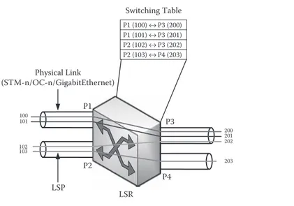
In MPLS or in GMPLS, as in ATM and Frame Relay, it is first necessary to
establish a logical path to transfer data and then perform the switching function. Such logical paths in MPLS/GMPLS are called LSPs (Label Switched Paths). Edge switches that receive an IP package and then retransmit it as an MPLS frame are called LER (Label Edge Router), and switches that are part of the device’s network core, that is, those that perform the switching function, are called LSR (Label Switch Router).
In MPLS, switching takes place through the value of LABELs, which are
con-figured along an LSP. Figure 1.36 shows a switching scheme in an MPLS network.
In this case, it is possible to transmit data from PC1 to PC2 or from PC2 to PC1 in their respective LAN networks, which are connected through a MAN or WAN net-work in MPLS. To exemplify this case, assume that right now PC1 wants to trans-mit a package (which can be IP in layer 3) to PC2. PC1 will forward an Ethernet frame placing its own address (PC1) as source MAC address and the LER1 MAC address as the destination MAC address. Based on the destination IP address (this will be explained in more detail in Chapter 3) associated to device PC2, LER1 will perform its routing function and decide to forward the package through the last-mile connection. Since the last-last-mile connection is in MPLS, LER1 will perform the encapsulation in MPLS assigning 100 as the LABEL value. Such LABEL values
are assigned by the carrier. This frame will follow the logical path marked by the
LSP. Next, the frame with LABEL 100 will arrive at the MPLS switch of carrier
LSR1 through last mile via port P1. Then, LSR1 through its switching table will
C
value (as indicated in LSR1’s switching table) and forward out the frame via port P2. Following the path of the LSP, the frame will come in at LSR2 via port P1, where switching will take place again from LABEL 200 to 300, and will be resent out via port P2. Subsequently, LSR3 will receive the frame with LABEL 300 and
reforward it via port P2 with LABEL 400 value until it finally reaches its
destina-tion network through the last mile with LER2. The LER2 will perform its routing
function, which will be explained later, to remove the layer 2 MPLS header and will replace the Ethernet header with the Ethernet destination MAC address of PC2 for delivery thereto.
When the switching function takes place in a network with optical switching, such function takes place at layer 1 of the OSI reference model. In GMPLS the
switching takes place through the value of the wavelengths (λ), which are confi
g-ured along an LSP. Figure 1.37 shows a switching scheme in a GMPLS network with OLS. At this point, it is important to clarify that there are different types of
optical switching, among them OLS/OCS, Optical Packet Switching (OPS), and Optical Bursa Switching (OBS), but for introductory purposes of the switching concept, only one example of OLS will be provided. A later chapter shows the operation of OPS and OBS. Picking up on the MPLS example, in this case one can transmit data from PC1 to PC2 or from PC2 to PC1 in their respective LAN networks, which are connected through a MAN or WAN network in GMPLS. To exemplify this case, assume that right now PC1 wants to transmit a package (which can be IP in layer 3) to PC2. PC1 will forward an Ethernet frame placing its own address (PC1) as source MAC address and the MAC address of LER1 as destina-tion MAC address. Based on the destinadestina-tion IP address (this will be explained in more detail in the Chapter 3) associated to device PC2, LER1 will perform its rout-ing function and decide to forward the package through the last-mile connection. Since the last-mile connection is in GMPLS, LER1 will transmit the bits through
the LAMBDA (λ) λ
1 value. Such λ values are assigned by the carrier. These bits will
follow the logical path marked by the LSP. Next, the bits being transmitted, λλ1,
will arrive at switch GMPLS of the LSR1 through the last mile via port P1. Then
LSR1 through its switching table will perform the switching function, switching the value λλ
1 for value λλ2 (as indicated in LSR1’s switching table) and forward
out the bits via port P2. Following the LSP path, the bits come in at LSR2 via
port P1, where switching will again take place from λλ
2 to λ3, and will be resent
out via port P2. Subsequently, LSR3 will receive the bits with value λλ
3 and will
reforward them via port P2 with value λλ
1 until finally they reach the destination
network through the last mile with LER2. LER2 will perform routing, which will be explained later, to reassemble the bits as a frame and add an Ethernet header with the Ethernet destination MAC address of PC2 for delivery thereto. In this example we have omitted the GMPLS control plane part because we want to show only the switching scheme in this section.
C
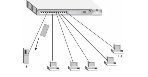
based on the MAC address of the destination device’s network card; in other words, the switching tables of the switches record through which physical port each of the device’s MAC addresses is.
Figure 1.38 shows a switching scheme in an Ethernet network. As in all the pre-vious cases, PC1 will transmit a frame to PC2, but in this case PC1 and PC2 are in the same LAN network and even in the same broadcast domain; that is, in the same VLAN (Virtual LAN), in case there are VLANs implemented in the LAN net-work. In this case, PC1 will include two fields in the frame to be transmitted within
the Ethernet header, where it will place MAC PC2 (whose value corresponds to the MAC address of the network card found physically in PC2) as destination MAC address and will place MAC PC1 (whose value corresponds to the MAC address of the network card found physically in PC1) as source MAC address. Next, this frame will arrive at the Ethernet switch via physical port P1 and will seek in the corresponding switching table the PC2 MAC address (MAC PC2). Once found, it will identify the physical port for such MAC address, which in this case would be PC2. Lastly, the switch will reforward the frame with destination PC2 via port P2.
This is how switching currently takes place in Ethernet, and we can conclude that
to perform this switching there is no need to construct a virtual circuit or LSP.
The foregoing switching scheme is inconvenient for the new challenges and uses
being given to this technology such as those for aggregation networks and core by Switch LAN MAC DESTI | MAC SOUR
MAC PC2 | MAC PC1
data operators. Standard 802.3ah (from the Institute of Electrical and Electronic Engineering) standardizes client network access to MAN or WAN networks of data operators. Even so, many data operators have implemented Ethernet as an
aggregation or core solution for their networks. The problem with this is that the
switching function is well defined for the LAN environment, but is not as
appro-priate for the MAN environment and so much less is for WAN. For this reason, research is taking place worldwide for the construction of LSPs in Ethernet or at least for a switching mechanism similar in technology to MPLS/GMPLS.
1.4.3 Routing
This function takes place when we must transmit data end-to-end through different
networks. This means that in this case it is possible to pass through different layer
2 network technologies. Here, it is also necessary to establish a path between the end-to-end networks so that the device in the source network can forward the data to the device in the destination network. Consequently, the routing function takes place in layer 3 of the OSI reference model. IP, the protocol used in the Internet, is a transmission protocol that operates at this layer.
In routing, data can be transmitted to different locations. The first type of
transmission is called unicast, where the data to be transmitted goes to a single des-tination device; in multicast we want to send the same data to a group of destination devices; in anycast we want to send data to any of the destination devices; and, last, in broadcast we wish to send the data to all the other devices.
Figure 1.39 illustrates a routing scheme based on IP that shows how it is pos-sible to pass through different layer 2 technologies. In this case, we want to
trans-mit data from a PC1 that is located in a LAN network through router R1 to PC2 that is located on another LAN network through R2 as the destination router. In order to forward such data from router R1 to router R2, it is necessary to establish an established path using a routing protocol such as RIP, OSPF, EIGRP, IS-IS, or
BGP, among others. The thick line shows the selected path.
Figure 1.40 shows the same scheme as in Figure 1.39 but with the correspond-ing routcorrespond-ing tables. In this case, we want to transmit a package from PC1, which is
located on a source network, to PC2, which is on a different destination network.
For the transmission to take place, it is necessary to follow these steps: First, PC1
sees that it is on a different network from the destination device (address IP PC2
30.0.0.1; for more information about IP routing see [COM05]); therefore, through switching, in case there is a switch at the connection between PC1 and router R1, or through physical broadcast, should there be a Hub, the data is forwarded from PC1 to its R1 link port via Ethernet, as shown in Figure 1.38. R1 sees that the IP address of the destination network (30.0.0.0) does not belong to its direct
con-nection and consults its routing table. The R1 routing table shows that to reach
network 30.0.0.0 the package must be resent to R3, and R1 it out through physical
N
e
tw
o
rk D
e
sig
n f
o
r I
P C
o
n
ve
rg
e
n
ce
Switch LAN
Ethernet
PC1
Router R1
IP PC2
Router R2
Switch LAN
Ethernet
PC2
IP PC2
R3 R4 R5
R7 R8 R10
R6
R9
C