FLAT VERSUS HEMISPHERICAL DOME PORTS IN UNDERWATER
PHOTOGRAMMETRY
F. Menna, E. Nocerino, F. Remondino
3D Optical Metrology unit, Bruno Kessler Foundation (FBK) Email: (fmenna, nocerino, remondino)@fbk.eu, Web: http://3dom.fbk.eu
Commission II
KEY WORDS: Underwater, Photogrammetry, Camera calibration, Flat port, Hemispherical dome port, MTF
ABSTRACT:
Underwater photogrammetry, like its counterpart in ‘air’, has gained an increasing diffusion thanks to the availability of easy-to-use, fast and often quite inexpensive software applications. Moreover, underwater equipment that allows the use of digital cameras normally designed to work in air also in water are largely available. However, for assuring accurate and reliable 3D modelling results a profound knowledge of the employed devices as well as physical and geometric principle is even more crucial than in air. This study aims to take a step forward in understanding the effect of underwater ports in front of the photographic lens. In particular, the effect of dome or flat ports on image quality in 3D modelling applications is investigated. Experiments conducted in a semi submerged indust rial structure show that the tested flat port performs worse than the dome, providing higher image residuals and lower pre cision and accuracy in object space. A significant different quality per colour channel is also observed and its influence on achievable processing results is discussed.
1. INTRODUCTION 1.1 Image quality in underwater photogrammetry
Underwater photogrammetry based on consumer grade photographic equipment is getting very popular in the last few years. Underwater housings are available for a big range of digital cameras, sometimes designed and sold by the manufacturer of the cameras themselves, sometimes from third parties companies.
Thanks to the great availability and flexibility in the configuration, photogrammetry experts and not are proving the importance of these systems as tools for documenting in 3D the underwater environment through SfM and photogrammetry in archaeology, biology, engineering, oceanography etc.
Sport cameras such as the very popular GOPRO HERO as well as SRL cameras have been tested and calibrated using the two most common popular approaches such as the rigorous ray tracing (Telem and Filin, 2010) or self-calibrating bundle adjustment (Shortis, 2015; Helmotz et al., 2016). Up to now, the effect of optical aberrations in underwater photogrammetry has not been investigated. In the authors’ knowledge, there are no papers that consider a diverse image quality across the sensor format nor the influence of a specific port setup on camera acquisition settings (depth of field, minimum focus distance, etc.) has been investigated.
This paper investigates the effect of using a dome or flat ports in underwater photogrammetry with respect to 3D modelling applications. In particular, the effect of the diverse image quality of flat and dome ports over the accuracy of the final 3D model is presented.
1.2 Flat and dome ports
Photographic cameras normally used on land, above the water, need a special housing with a flat or dome port to be used also in water. Looking to the underwater scene through a flat or dome port has many optical consequences of which the most known is that the field of view of the lens mounted on the camera is preserved in case of a dome port and reduced of a factor (almost
equal to the refractive index) for the flat port. In general, this common rule is satisfied but there are many other factors that intervene in the optical formation of the image some with very important practical implications that may make the choice of a type of port with respect to another one not as trivial as described above.
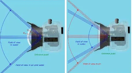
Lenses used in photography are designed to minimize optical aberrations throughout the entire image format. Residual aberrations are always present and their amount is depending on the optical design, quality of glasses and therefore cost of the lens. Nowadays, even the cheap kit zoom bundled with consumer cameras, provide an acceptable image quality for less demanding photogrammetric purposes. Nevertheless, when used underwater behind flat and dome ports, image quality, even for the most expensive cameras, undergoes a quite visible degradation due to the modification of the entire optical design. Depending on the combination of the used lens and port (spherical dome or flat), the consequences on the overall image quality may be disappointing. Figure 1 depicts the main optical effects over the field of view with dome and flat ports.
Figure 1. Field of view underwater with dome (left) and flat port (right).
The spherical surface of the dome has the effect that optical rays converging to the centre of the sphere do not change their direction as they enter the surface of the dome perpendicularly. The main consequence of this phenomena is that with dome ports
the field of view is kept unchanged also underwater. Nevertheless, if the centre of the dome is not aligned with the entrance pupil of the lens, modifications of field of view and distortions may be introduced (Menna et al., 2016; Nocerino et al., 2016). Unfortunately, spherical domes have as main drawback that they act as negative lenses that form a virtual image very close to the spherical dome. The distance between the dome centre and the virtual image is approximately three times the radius of the sphere thus meaning for example that an object at infinity would be projected at only 30 cm from the entrance pupil of the lens when using a 10 cm radius spherical port. If the camera lens were not able to focus at that close distance, the image would result blurred and thus unusable. The solutions for this problem are that one may use a bigger dome or add an additional close-up dioptre lens to the front of the camera lens to reduce its minimum focus distance. Unfortunately, the cost for manufacturing spherical domes grows significantly with its radius and some lenses, like for example fisheye lenses, cannot accept additional close up dioptres. In these cases, a flat port must be used.
The first two versions of the popular sport camera GOPRO used to have a spherical dome port mounted on the front of the lens of the underwater pressure housing (Figure 2 left-up). Because of the very small radius of the dome, the virtual image would project too close to the camera, far behind the limits of the depth of field of the fixed focus fisheye lens of the camera thus resulting in
slightly blurred images
(https://gopro.com/support/articles/underwater-focus).
Figure 2. GOPRO HERO dome and flat ports. An early underwater housing with dome port for GOPRO HERO 1 and 2 cameras (left-up). An optional flat port replacement housing for GOPRO HERO 1 and 2 (left-down). A schematic view of the reduced field of view because of flat port critical angle (right).
Successively, GOPRO released an optional replacement underwater housing for the GOPRO HERO 1 and 2 with a flat
port and then from the versions 3 onward only pressure housings with flat ports were released which at cost of a reduced field of view provide sharper images. Another undesired effect introduced by spherical dome ports is that it makes the images softer towards the corners of the image (Nocerino et al., 2016). Flat ports have the advantage of a much simpler and thus cost effective manufacturing and are largely used in pressure housings of sport cameras or very compact zoom lens cameras. One of the main drawbacks of flat ports is that the field of view is reduced of a factor that is approximatively equal to the refraction coefficient of the water. Additionally, the maximum field of view allowed by this ports is 96 degrees, therefore fisheye cameras like the GOPRO cameras, when used behind a flat port lose their extremely wide angle feature (Fig. 2 right).
Wide angle lenses used with flat ports show strong chromatic aberrations toward the corners of the image.
The effect of chromatic aberrations in close range photogrammetry has been investigated mainly for high precision photogrammetric applications where the effect of separate image measurements for each colour channel can lead to a significant accuracy enhancement of a factor about 1.3 (Luhmann et al., 2006). Other rigorous methods that consider a colour or multi spectral dependent calibration and processing are discussed in (Reznicek et al. 2016; Robson et al., 2014; Matsuoka et al., 2012).
Optical aberrations in underwater photography are much more severe and difficult to correct with respect to those generally seen for regular cameras above the water. If the quality of the image is important in close range photogrammetry it is even more important for underwater photogrammetry were a correct framing of the subject can be difficult to achieve underwater leading generally to not as well-structured acquisitions as those achievable above the water; thus any part of the image can be fundamental for an accurate reconstruction of the scene and for image interpretation purposes.
2. EXPERIMENTAL WORK
The application presented in this contribution is part of a wider project called OptiMMA (Optical Metrology for Maritime Applications, http://3dom.fbk.eu/projects/underwater -photogrammetry-maritime-applications).
2.1 The modelled heritage structure
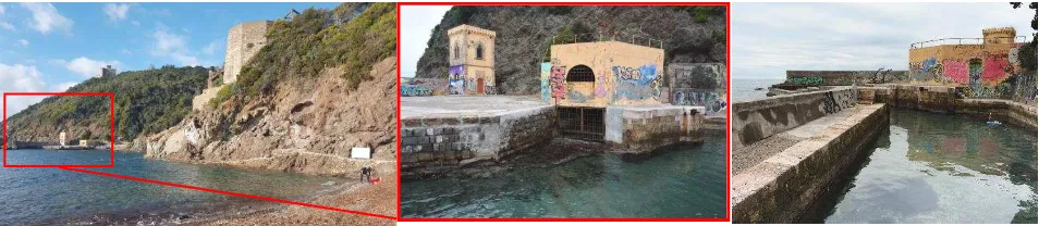
A semi-submerged industrial structure located in the Bay of Rogiolo near Livorno (Italy), today abandoned and under consideration for restoration (Fig. 3), was used as test site. The structure was used as a port and support for cave and cement plan activities carried out nearby at the beginning of the 20th century. A combination of close-range photogrammetry above and under the water according to the procedure described in Menna et al. (2015, 2013) was chosen for modelling the structure.
Figure 3. The surveyed port structure in the bay of Rogiolo near Livorno, Italy.
Figure 4. Nikon D750 camera, Nikkor AF 24 mm f/2.8D, NiMAR NI3D750ZM pressure housing and different ports used (from left to right).
The part of the structure underwater was photographed twice, the first time using a dome port and the second time using a flat port mounted on the same pressure housing. For the whole survey the sky was overcast limiting the effect light ripples on the underwater structures. The aim is to investigate the effect of dome and flat ports on the 3D modelling results.
2.2 Photographic equipment
A Nikon D750 24 Mpx full frame camera mounting a Nikkor AF 24mm f2.8/D wide angle lens was put in a NiMAR NI3D750ZM pressure housing (Fig. 4). In order to guarantee the highest accuracy each image acquisition was carried out with fixed focus set for the first image of the sequence. The distance to the object was kept constant through both visual references and using ropes with marks. Between the different surveys, just the port was changed and then the adjustment of the focus done. A Nikon SB700 strobe mounted in a dedicated NiMAR housing was used for the underwater calibrations.
2.3 Underwater camera calibrations
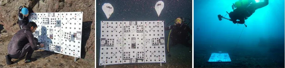
Before carrying out the survey of the structure, preliminary calibrations using an in-house portable testfield (Fig. 5) were performed to assess the optical quality of the photographic system used and its potential accuracy when used with flat and dome ports. The portable testfield was specifically designed by the authors for underwater calibrations, it measures 150x100 cm2 and consists of three Dibond panels each of 100x50 cm2 fixed on an aluminium frame. 6 plates stand with different heights from the main planar surface of the portable testfield providing a maximum depth of 20 cm. A total of 160 circular coded targets are regularly distributed over the testfield, furthermore, the targets are designed with a black square background that allows MTF measurements. Also, other resolution wedges and colour checkboards are present.
The portable testfield was laid down at a depth of about 5 meters and photographed from an average distance of about 1.2 m for the dome port and 1.6m for the flat port. The ground sample distance (GSD) was about 0.3mm for both the calibrations. An aperture value of f/11 was chosen for both the flat and dome ports. About 30 images per each port were collected using quite a standard self-calibration protocol with multi-view convergent images and roll diversity (Fraser, 1997). The image acquisitions were carried out in sequence, the dome port first and the flat port after.
As expected, from the visual analysis of the acquired images , while the dome port kept the barrel distortion of the lens almost unchanged (Fig. 6a), the flat port introduced a heavy pincushion distortion (Fig. 6b). Furthermore, the image quality for the flat port resulted severely different between the centre (Fig. 6c) and the corners showing some severe chromatic aberrations (Fig. 6d) and some blur astigmatism that was different per red, green, and blue channels with the blue channel behaving the worst (Fig. 7). From the successive bundle adjustments with self-calibration (Brown model formulation with radial and decentring distortions) the flat port also performed quite significantly worse than the dome port. The reports of the bundle adjustment highlighted a higher potential accuracy for the dome port with respect to the flat port (image observation from green channel for both ports). Table 1 synthetically summarizes the results together with reference values for the same camera lens system calibrated above the water in the laboratory of 3DOM research unit.
No housings in LAB
Dome port UW
Fla t port UW RMS of image
residual
0.26 px 0.34 px 0.91 px
RMSσXYZ 0.023mm 0.050mm 0.099 mm
Table 1. Summary of the self-calibrating bundle adjustment.
Figure 5. The testfield used for underwater calibrations during the assembly (left) and image acquisition (center and right). The International Archives of the Photogrammetry, Remote Sensing and Spatial Information Sciences, Volume XLII-2/W3, 2017
a) b)
c) d)
Figure 6. Portable testfield underwater as imaged by the dome port (a) and flat port (b). Enlarged views of the image taken with the flat port at the centre (c) and at the up right corner (d) of the testfield.
Figure 7. The colour dependant astigmatic aberrations noticed with the flat port (red on the left, green in the centre, blue on the right)
The camera calibrations anticipated a minimum reduction of the potential accuracy in object space of a factor about 2 with the dome port and 4 with the flat port.
2.4 Targeting of the industrial structure
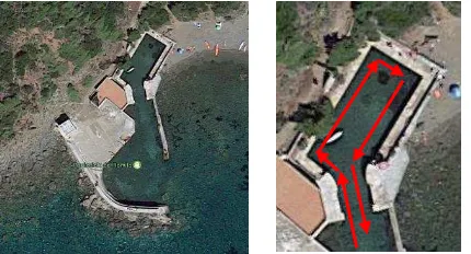
A rectangular basin measuring about 20x10m2, part of the industrial structure, was chosen to perform the comparative photogrammetric tests (Fig. 8).
8 plates with 8 coded target each were placed across the waterline (Fig. 9). The coded targets were placed for the twofold aim of: (i) allowing to register the underwater and above the water 3D models and (ii) having well and uniquely defined 3D points to perform comparisons between flat and dome port underwater surveys. The relative positions of the targets on the plates are known by laboratory calibration, thus by measuring at least three non-collinear targets in the underwater or above the water photogrammetric surveys, the 3D coordinates of the remaining targets can be computed through a similarity transformation. By means of these procedure common points between underwater and above the water surveys can be derived and the two 3D models registered together. Some tape length measurements were carried out to scale the object.
Figure 8. An aerial view of the port structure (left) and an enlarged sight of the rectangular basin chosen for the tests with a schematic view of the photogrammetric strip acquired (right).
2.5 Planning and acquisition of the underwater and above-the -water camera network
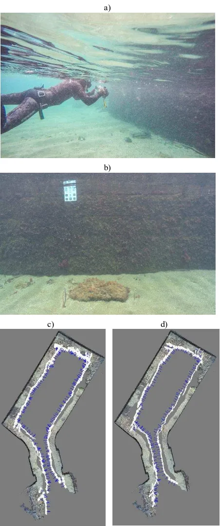
Since from the preliminary calibrations the two ports behaved differently, a much evident discrepancy between the two ports would be expected in elongated strips such as those usually carried out for surveying big objects in photogrammetry. Indeed, systematic residual errors not properly modelled by the camera calibration parameters are expected to accumulate along the strip, thus leading to global object deformation as seen in Nocerino et al. (2014). Thus, the camera network planned to image the rectangular basin consisted in a singular open loop strip taken at a distance of about 2 m from the vertical walls for the dome port and 2.6 meters for flat port to obtain for both the ports a GSD of about 0.5 mm. A 80% overlap was considered along the strip and some convergent and rolled images were taken to improve the self-calibration (especially considering the geometric characteristics of the object that results flat within the field of view of the single images). The image acquisitions were carried out in sequence, the dome port was used as first and the flat port after (Figure 10a-b). The maximum depth was 1.5m, water temperature was about 15 degrees and the underwater image acquisition required about 3 hours in total. The part above the water was surveyed with the same camera without the pressure housing. The available side walking path was used to photograph the structure on the opposite side thus leading to an average distance to the object of about 12 m (GSD about 3 mm). Same 80% overlap with rolled and convergent image acquisition protocol was used above the water.
Figure 9. Plates with coded targets used in the experiment.
2.6 Image orientation and bundle adjustment with self-calibration
The three image datasets, two underwater and one above the water were processed with the same procedure. A non expert user scenario for basic 3D modelling purposes (e.g. a preliminary 3D investigation of the structure) was simulated. The images were automatically oriented using Agisoft Photoscan where self calibration on radial and decentring distortion parametrs were computed. The fnal camera network for the dome and flat ports is shown in Figure 10 (c,d).
a)
b)
c) d)
Figure 10. Underwater image acquisition (a) and a sample image fro m the dome port (b). Final camera networks for the dome port (c) and flat port (d).
From a preliminary comparative analysis of the bundle adjustment parameters retrieved by Photoscan for the two underwater datasets, again the flat port confirmed a less precise solution.
Systematic residual errors in the image space are evident for both the ports but in the flat port they were higher in magnitude and especially concentrated at the left and right borders of the image format (Fig. 11).
A very important difference was observed on the self calibration parameters. While for the dome port the standard deviations for the focal length was 0.4 um, for the flat port the standard devition
Figure 11. Systematic residual errors for the dome port (left) and flat port (right)
resulted 1.4 um, more than three times worse. In general, the self calibration parameters of the flat port were an order of magnitude worse than those computed for the dome port. Such a worse precision is expected to be a source of systematic errors that accumulates along the photogrammetric strip and “vent” into the object space leading to a stronger global deformation of the 3D model for the flat port. Therefore, as shown in Nocerino et al. (2014), over the 70 meters linear perimeter of the underwater basin, the global deformations can reach some centimeters, even if the GSD was sub-millimetric.
For the above the water dataset as expected, the precison of calibration parameters was much higher with a standard deviation for the focal length of 0.1 um more than ten times better than the the one of flat port.
The three datasets were scaled using a combination of lengt h measuremnts provided by the plates and some tape measurements. A maximum scaling error of about 0.2% was estimated from the residuals on the reference known lengths.
2.7 Accuracy and 3D analysis in object space
A simple evaluation was carried out to asses the accuracy of the two underwater surveys. A reference tape measurement distance (estimated accuracy ca. 1cm) was taken between the two plates facing each other at the entrance of the rectangular basin and compared with those obtained from the underwater survey (Table 2). Being the two plates at the beginning and end of the strip the resulting discrepancy can be seen as a loop closure error. An error about 30 cm was observed for the flat port.
Reference distance DOME FLAT
4.723 m 4.729 m 5.015 m
Error 0.006 m
(≈12xGSD) (≈600xGSD)0.292 m
Table 2. Summary of the length checks
2.8 Photogrammetric processing of the single R,G,B channels
As already mentioned in section 2.3, the three channels for the flat port showed different image quality, especially at the corners. The three R,G,B channels for both the flat port and dome port were then extracted from the RGB images and saved as single channel image to be processed separately.
For the flat port only the Red and Green channels succeeded the orientation stage. On the contrary, the images in the Blue channel probably resulted too blurred and were only partially oriented. The three channels for the dome port could be oriented without any particular difficulty.
Being the images in the three channels taken from the same position and exactly with the same camera network, the results in object space are expected to be not significantly different between them. Thus an inner comparison between the three channels of each port was performed by comparing the 3D coordinates of the plates obtained separately from each channel. According to Photoscan manual, the default processing considers
a combination of the three R,G,B channels. Thus being the previous results (Section 2.6 and 2.7) obtained in default mode, they were used as reference for the relative comparisons. A similarity transformation with isotropic scale factor was computed to compare the 3D coordinates. The Euclidean distances between same points were used as measure of discrepancy. Table 3 summarizes the relative comparison for each channel per each port reported as RMS and maximum discrepancy between 3D points. A maximum difference of 23 cm is observed between the red channel of the flat port and the RGB combination for the same flat port. The solutions between the three channels of the dome port result more consistent between themselves.
The discrepancy between the reference distance and the one measured in the green channel of the flat port reduced from 29 to 21 cm (≈400xGSD). The difference between RGB combination and green channel for the dome port was not significant, stating the accuracy of the reference measurement.
DOME FLAT
RMS [m] Max [m] RMS [m] Max [m]
RED 0.005 0.013 0.096 0.229
GREEN 0.003 0.006 0.023 0.055
BLUE 0.010 0.023 n/a n/a
Table 3. Summary of the relative comparison between 3D coordinates obtained from the single R,G,B channels and the one obtained as RGB combination for each port.
2.9 3D modelling of the structure
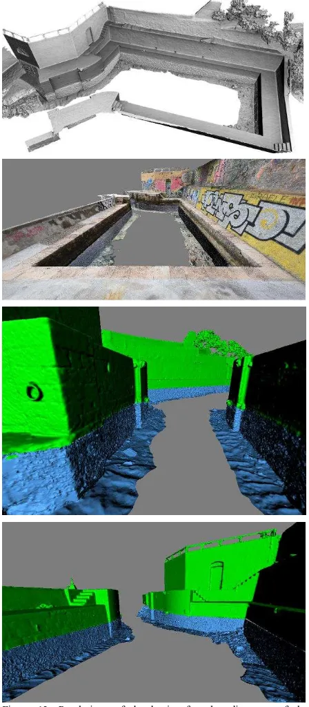
Dense point clouds were computed at 1/8 and 1/4 linear resolution respectively for the dome port and the above-the-water photogrammetric surveys corresponding to a spatial resolution of 4 mm in the object space. An optimized mesh according to Rodriguez et al. (2015) was wrapped over the manually cleaned point clouds for each dataset. The joint alignment procedure presented in Menna et al. (2015, 2013) was used for registering the underwater mesh with the one above the water. The RMS of the transformation was some 3 cm for the dome port and 13 cm for the flat port. Figure 12 shows some renderings of the basin after the alignment of the underwater (dome port) and above-the-water 3D models.
3. DISCUSSIONS AND FUTURE WORKS The paper investigated the effect of the diverse image quality of flat and dome ports over the accuracy of the final 3D model obtained through photogrammetric procedures. The paper highlighted the importance of image quality over the global accuracy of the final 3D model. Image quality underwater undergoes a very evident degradation due to the sum of optical phenomena arising from both the pressure housing and port used and the physical and environmental properties of water itself. Indeed, due to the combination of optical aberrations such as astigmatism, heavy distortions and chromatic aberrations plus a non-complete modelling of unknown systematic image errors, strong global deformations were observed and assessed trough simple length measurements for the two ports. A very high error of some 29 cm was found with the flat port. Preliminary calibrations on a portable testfield anticipated a degradation of accuracy when using the flat port by reporting high RMS of image residuals, a less precise calibration (worse standard deviations for camera parameters) and a lower 3D point precision in object space. A significant different image quality per colour channel was observed and different processing for each colour carried out. As expected, the green channel performed more similarly to the RGB combination than the other channels as the
digital sensor of the Nikon D750 uses the Bayer filter array. The green channel for the flat port provided an improved accuracy of 33% with respect to the processing obtained from the combination of the R,G,B channels. The blue channel proved to be the most problematic and might probably degrade the accuracy when combined with the other channels. This test was important because software applications may combine the three channels by default, which may be not the best procedure for underwater photogrammetry.
The issues risen by this study may deserve more experimental tests for example using different housings and ports. Having observed a strong difference between image quality between the centre and corners, successive tests will take into account a different weighting for image observations according to optical quality parameters (e.g. Modulation Transfer Function-MTF).
Figure 12. Renderings of the basin after the alignment of the underwater and above-the-water 3D models.
ACKNOWLEDGEMENTS
The authors would like to thank Dr. Francesco Fassi from Politecnico di Milano and Barbara de Cillis for supporting the diving activities during the underwater calibrations. A thank to NiMAR which supported this research by providing the photographic underwater equipment and for the useful insights about pressure housings manufacturing techniques; Sara Messina and Stefano Pucher from the Associazione Sportiva Dilettantistica Club Subacqueo Rane Nere Trento who supported the preliminary tests in the swimming pool in Trento.
REFERENCES
Fraser, C.S., 1997. Digital camera self-calibration. ISPRS J ourna l of Photogra mmetry a nd Remote sensing, Vol. 52(4), pp.149-159.
Luhmann, T., Hastedt, H. and Tecklenburg, W., 2006. Modelling of chromatic aberration for high precision photogrammetry. ISPRS Int. Archives of Photogra mmetry, Remote Sensing and Spa tia l Informa tion Sciences, Vol. 36(5), pp. 173-178).
Helmholz, P., Long, J., Munsie, T. and Belton, D., 2016. Accuracy assessment of GOPRO Hero 3 (Black) camera in underwater environment. ISPRS Int. Archives of the Photogra mmetry, Remote Sensing a nd Spa tia l Informa tion Sciences, Vol 41(B5), pp.477-483.
Matsuoka, R., Asonuma, K., Takahashi, G., Danjo, T., and Hirana, K., 2012. Evaluation of correction methods of chromatic aberration in digital camera images. ISPRS Anna ls of Photogra mmetry, Remote Sensing a nd Spa tia l Informa tion Sciences, Vol. I-3, pp. 49-55.
Menna, F., Nocerino, E., Fassi, F. and Remondino, F., 2016. Geometric and optic characterization of a hemispherical dome port for underwater photogrammetry. Sensors, Vol. 16(1).
Nocerino, E., Menna, F., Fassi, F. and Remondino, F., 2016. Underwater calibration of dome port pressure housings. ISPRS Int. Archives of the Photogra mmetry, Remote Sensing and Spa tia l Informa tion Sciences, Vol. 40(3-W4), pp.127-134.
Menna, F., Nocerino, E., Troisi, S. and Remondino, F., 2015. Joint alignment of underwater and above-the-water photogrammetric 3D models by independent models adjustment. ISPRS Int. Archives of Photogra mmetry, Remote Sensing and Spa tia l Informa tion Sciences, Vol. 40(5), p.143.
Menna, F., Nocerino, E., Troisi, S., Remondino, F., 2013. A photogrammetric approach to survey floating and semi-submerged objects. Proc. of Videometrics, Ra nge Ima ging and Applica tions XII, SPIE Optica l Metrology, Vol. 8791, doi: 10.1117/12.2020464.
Nocerino, E., Menna, F. and Remondino, F., 2014. Accuracy of typical photogrammetric networks in cultural heritage 3D modeling projects. ISPRS Int. Archives of Photogra mmetry, Remote Sensing a nd Spa tia l Informa tion Sciences, Vol. 40(5), pp. 465-472.
Reznicek, J., Luhmann, T. and Jepping, C., 2016. Influence of raw image preprocessing and other selected processes on accuracy of close-range photogrammetric systems according to VDI 2634. ISPRS Int. Archives of the Photogra mmetry, Remote Sensing a nd Spa tia l Informa tion Sciences, Vol 41(B5), pp.107-113.
Rodríguez-Gonzálvez, P., Nocerino, E., Menna, F., Minto, S. and Remondino, F., 2015. 3D surveying & modeling of underground passages in WWI fortifications. ISPRS int. Archives of Photogra mmetry, Remote Sensing a nd Spa tia l Informa tion Sciences, Vol. 40(5), pp. 17-.24
Robson, S., MacDonald, L., Kyle, S.A. and Shortis, M.R., 2014. Multispectral calibration to enhance the metrology performance of C-mount camera systems. ISPRS Int. Archives of Photogra mmetry, Remote Sensing a nd Spa tia l Informa tion Sciences, Vol. 40(5), p.517.
Shortis, M., 2015. Calibration techniques for accurate measurements by underwater camera systems. Sensors, Vol. 15(12), pp. 30810-30826
Telem, G. and Filin, S., 2010. Photogrammetric modeling of underwater environments. ISPRS J ourna l of Photogra mmetry a nd Remote Sensing, Vol. 65(5), pp.433-444.