A NOTE ON FRAME SNCHRONIZATION SEQUENCES Thokozaui Showe, ictor . Papi/_va
A NOTE ON FRAME SYNCHRONIZATION SEQUENCES
codes
Thokozani Shongwe1, Victor N. Papilaya2
1 Department of Electrical and Electronic Engineering Science. University of Johannesburg
P.O. Box 524. Auckland Park. 2006, Johannesburg, South Africa
e-mail: tshongwer<�;uj .ac .a
Satya Wacaa Christian University JJ. Diponegoro 52-60. Salatiga 5071 1. ndonesia
e-mail: victor. papiJayar';staf. uks' Y. edu
ABSTRACT
An introduction into binary sequences used for frame synchronization is given, together with criteria used in designing and/or inding optimal sequences that can be used as markers. Two approaches to the choice of optimal sequences for frame synchronization are presented, one approach focuses on the good properties of the marker and the other focuses on both marker and the data used in a frame. To illustrate the importance of "good" marker choice, simulations are presented showing the performance of "good" and "bad" marker choices.
Techne Jurnal Ilmiah Elektroteknika Vol. 11 No. 1 April 2012 Hal 37-47
l. WHY SYNCHRONIZATION?
In Digital communications, synchronization ts essential if reliable communications is to take place between a transmitter of information and a receiver of information. To explain why synchronization is necessary, we explain what synchronization is for digital communications. Consider a simpliied digital communications system consisting of a transmitter, a channel and a receiver of information. The basic element of information is considered to be a bit, from which blocks (of bits) can be formed and called sequences/words or frames. For the receiver to "make sense" of the transmitted information, it must know when a bit starts and ends (bit period/duration). This bit period should be agreed upon between the receiver and transmitter, that is, clocks at the receiver and transmitter must be syncronized. Bit synchronization is the irst level of synchronization; the next level is to synchronization a group of bits forming a frame, which is called rame synchronization. In frame synchronization the receiver is interested in knowing the beginning and end of every rame sent to it. Obviously, frame syncronization can only work if bit synchronization has already been achieved. There are two well known methods of synchronization for blocks of data bits namely, marker based frame synchronization and bounded synchronization delay (BSD) codes. Discussion in this paper is limited to the design
markers used in frame syncronization, only a brief discussion will be given on BSD in Section IV.
2. FRAME SYNCHRONIZATION USING MARKERS
2.1. Frame Synchronization Algorithm
A NOTE ON FRME SYNCHRONIZATION SEQUENCES Thokozaui h.we, Victor N Papiya
the received data and at each window period the data is compared for Hamming distance
or correlated with the known marker.
Let the following parameters be deined to enhance the description of a
synchronization algorithm.
A S: synchronization word or synchronization sequence or marker, deined as {S1S2
... SNl·
A N: synchronization sequence length (number of symbols making up a
synchronization sequence).
A H: error tolerance threshold of the synchronization algorithm (that is, any N-tuple
of received symbols that difer to the marker in at most H positions is declared the
marker.)
A L: number of data symbols in a synchronized frame.
A Pe: symbol error rate.
A frame is then made up ofL data symbols and N marker symbols as shown in
Fig. 1, where three frames are shown to give an idea of a continuous transmission of data
with periodically embedded markers.
Sr S2 ••• D1 D2 ••• Dt St 52 ••• Dt+l Dt+2 ••• D2t 5r 52 ••• D2L+I D2L+2 ••• DJL
SN SN SN
Fig_ 1. Framed sequences of received symbols with synchronization sequences
There can be various algorithms for the marker search using the sliding window
and correlation, but in general the algorithm should look something like this.
l. From the initial received symbol, pick symbols of length equal to the known
marker, anN-tuple of symbols called a window.
2. Compare theN-tuple received symbols with the known marker for agreements
according to a set error tolerance threshold, H.
a. If the N-tuple satisy the error tolerance threshold, the algorithm declares a
marker found and a search for the next marker begins.
b. If the N-tuple does not satisfy the error tolerance threshold, the algoritluu
Techne Jurnal Ilniah Elektroteknika VoL 11 No. 1 April2012 Hal37- 47
[5] sequences. These sequences have good aperiodic autocorrelation unctions (ACFs)
which make them "optimal" markers, and what that basically means is that the sequence
only produces an aperiodic autocorrelation function that has a high main lobe and
minimal side lobes when correlated with zero-shited version of itself Using a Barker
sequence, the following example illustrates a marker with a good autocorrelation
unction.
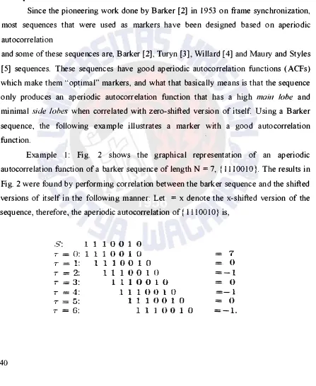
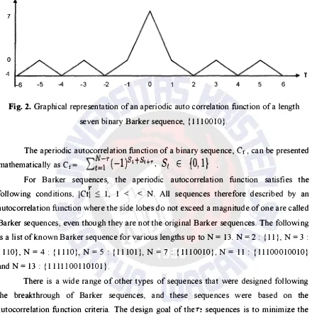
Example 1: Fig. 2 shows the graphical representation of an aperiodic
autocorrelation unction of a barker sequence of length N = 7, { 1110010}. The results in
Fig. 2 were found by performing correlation between the barker sequence and the shited
versions of itself in the following manner: Let = x denote the x-shited version of the
sequence, therefore, the aperiodic autocorrelation of { ill 0010} is,
A NOTE ON FME SYNCHRONIZATION SEQUENCES Thokozani honwe, ictor . Papilaya
The values of the ACF at each T = x result into what is called side lobes for x t 0, and
main lobe at x = 0.
7
0
-1
-6 -5 4 -3 -2 -1 0 2 3 4 5 6
Fig. 2. Graphical representation of an aperiodic auto correlation unction of a length
seven binary Barker sequence, { Ill 00 1 0}.
The aperiodic autocorrelation unction of a binary sequence, C r , can be presented
)S tS
{ }
mathematically as C r = 1
-1
' t+r.St
E0) 1. .
For Barker sequences, the aperiodic autocorrelation function satisies the T
following conditions, !Ctl S 1, 1 < < N. All sequences therefore described by an
autocorrelation imction where the side lobes do not exceed a magnitude of one are called
Barker sequences, even though they are not the original Barker sequences. The following
is a list of known Barker sequence for various lengths up to N = 13. N = 2 : : 1 1 } , N = 3 :
{ 11 0 } , N = 4 : p 1 1 0}, N = 5 : { Ill 0 1 }, N = 7 : { Ill 00 10}, N = 1 1 : p 1 1000 1 00 10}
and N = 13 : { 1 1 1 1100 1 1 0 10 1}.
There is a wide range of other types of sequences that were designed following
the breakthrough of Barker sequences, and these sequences were based on the
autocorrelation unction criteria. The design goal of then sequences is to minimize the
side lobes of the ACF. Binary sequences with low values of the ACF (except at = 0) are
not only suitable for frame synchronization, but for a number of applications as well,
some of which are radar pulse-compression, spread spectnun communications and stream
Techne Jurnal Ilmiah Elektroteknika Vol. 11 No. 1 April 2012 Hal 37- 47
While considering the ACF as the criterion for designing/searching for optimal
markers is a good guideline, there are other ways of looking at the problem of marker
design. One such criterion was presented by Scholtz in 1980 [ 1 ], which is consideration
of the probability of false acquisition on data, PFAD and probability of true acquisition on
the marker, \J. We shall not elaborate urther on this design criteria in this paper.
3. GOOD AND BAD MARKER CHOICES
In this section, simulation results are presented to show examples of good and bad
marker choices. It is urther explained why one particular sequence is preferred over
another as a marker. A binary symmetric channel (BSC) was used for the simulations.
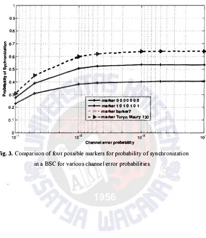
Figs. 3 and 4 show similar graphs of comparison of two examples of bad markers and two well known optimal markers. The two well known optimal markers used in the
simulation are (a) Barker sequence of length seven, { Ill 00 l 0}, and (b) a sequence
common to both Turyn sequences, and Maury and Styles sequence, { 1011000}. It should
be noted that the Turyn, and Maury and Styles sequence in (b), {1011000}, satisy the
Barker condition in the ACF (!Cl Sl , I < < N), hence the equal performance to the Barker sequence in (a). n both Figs. 3 and 4, a same .symbol sequence and periic
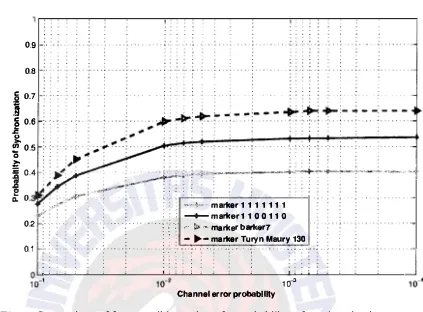
sequence are used as the two examples of bad markers. In Fig. 3 sequences { 0000000} and { 1010101} are used, and In Fig. 4 sequences { 1111111} and { 1100110} are used.
The sequences; { 0000000}, { 10 1010 1 } , { 1111111 } and { 11 00 11 0} all perform
worse than the Barker ( { Ill 00 10} ), and Turyn, Maury and Styles sequence ( { 1011000})
because they have larger side1obes in their ACFs. The same symbol sequences are the
worst because they have ACFs with the highest sidelobes compared to all the sequences
in question. The procedure introduced in Example 1 can be used to veriy this conclusion
on the performance of the sequences based on ACF.
In the simulations, a simple correlation rule was used to locate the marker in the
rame. In the correlation rule, the entire frame is searched for the marker and the N-tuple
with lowest Hamming distance with the marker is declared a marker. When there are
more than one N-tuples with lowest Hamming distance the algorithm declares
synchronization failure as well as when the Marker is declared in the wrong position.
A NOTE ON FRAME SYNCHRONIZATION SEQUENCES Thokozani honwe, Victor . Papilaya
0.9
Techne Jurnal Ilmiah Elektroteknika Vol. 11 No. 1 April2012 Hal37- 47
Fig. 4. Comparison of four possible markers for probability of synchronization
in a BSC for various channel error probabilities.
4. BOUNDED SYNCHRONIZATION DELAY BLOCK CODES
Apart from using frames composed of data and markers, there are other ways of
achieving synchronization in digital transmission. In this section, a class of codes called
Bouuded .sJmchrouization delay
(BSD) is discussed as another option to the frame synchronization. BSD codes are synchronizable codes withunique(v decodable
codewords, which when their codewords are sent through a noiseless channel, a receiver
can be able to tell the boundaries of the codewords ater observing d, symbols. The
parameter
d1
is the synchronization delay of the codes and is bounded by some value inrelation to the codewords' length, hence the term BSD. BSD codes can be variable length
(examples here are source codes) or fixed length. Variable length BSD codes are outside
12040351
A NOTE ON FRME SYNCHRONIZATION SEQUENCES Thokozani howe, T'ictor . Papiyato as block codes. BSD block codes can be divided into three main classes, comma-free
codes, prefix coes and comma codes.
4.1. Comma-Free Codes
This class of BSD block codes has been extensively studied. t was irst
introduced by Golomb et. al in 1958 [7], where they formalised it as follows. Given a
block code, Band codewords X= { x1x2 ... xn} and Y = { YtY2 . . . Yn} of length n, where X,
Y € B. B is a comma free code if, and only if, for any n-tuple, Z resulting from the
overlap of X and Y , Z = { Xt ... XnY 1 ... Yi-J}, Z is not element of B for 2 :; i :; n.
Eastman [8], was the irst to present a constmction that achieves the maximum
cardinality comma-free codes, for n odd.
4.2. Preix Codes
Preix codes were irst advanced by Gilbert [ 1 0] in his article on synchronization
of binary messages. These codes are constmcted by appending aN-tuple sequence (called
a prefix) to every n-symbol sequence such that the (N + n)-symbol sequence is a uniquely
decodable codeword of codebook. It should be noted that N-tuple sequence is the same
for every n-symbol sequence and it is appended to indicate the start of each codeword,
hence allowing synchronization of the codewords. For synchronization to be possible all
the time, in the absence of errors, the N-tuple preix should not be part of any codeword
or should not be formed by an overlap between a codeword and the preix itself.
4.3. Comma Codes
In comma codes, codewords of a particular length say, n, are chosen from a
codebook to be transmitted and ater k codewords, a special N-tuple sequence is inserted
in the transmission as a comma. These codes are more attractive for implementation
because the requency with which the comma is inserted in the transmission can be varied
according to the channel propeties. The constraints in the choice or design of a comma in
the comma codes are, the comma should not be any of the n-tuple codewords, an overlap
Techne Jurnal Ilmiah Elektroteknika Vol. l l No. 1 April 2012 Hal 37-47
n-tuple codeword should not produce the comma. Related work in this area can be found
in [11] and [12].
5. CONCLUSION
The question of why we need synchronization and bow it can be achieved in
digital communications was answered using a known technique of frame
synchronization, with the assumption that symbol synchronization was already
established. Then a study for markers for rame synchronization was presented in this
article, where aperiodic correlation function properties of the marker were discussed. It
was also shown that another approach to the marker formulation problem is to study the
data not containing the marker and in this approach, the probabilities of false and true
acquisition needed to be computed. In all the cases, the data was considered to be
composed of Q-ary symbols randomly selected from an alphabet of size Q with equal
probability. Another more interesting scenario, addressed in the Subsection IV-C on the
subject of comma codes, is when the data is chosen as codewords from a codebook and
then appending a marker at speciic ixed intervals.
REFERENCES
[ 1] R. A. Scholtz, "Frame synchronization techniques," IEEE Transactions on
Communications, vol. is, no. 8, pp. 1782-1789, Aug. 1980.
[2] R. H. Barker;'Group synchronizing of binary digital systems," in Communication
Theory, W. Jackson. Ed. New York: Academic-Butterworth, 1953.
[3] R. Turyn, ''Sequences with small correlation," Error Correcting Codes, pp. 195-228,
H. B. Mann, Ed. New York: Wiley, 1968.
[4] M. W. Willard, "Optimum code pattens for PCM synchronization,"in Proc. 1962
National Telemetering Conference, Washington, C. May 1962, paper 5-5.
[5] J. L. Maury and F.J. Styles, "Development of optimum frame synchronization codes
for Goddard Space Flight Center PCM Telemety Standards," in Proc. 1965 National
A NOTE ON FRME SYNCHRONIZATION SEQUENCES Thokozaui houwe, ictor N Papia
[6] J. J. Stiier, Theory of Syncronous Communications. New Jersey: Prentic-Hall, Inc.,
1971.
[7] S. W. Golomb, B. Gordon, and L. R.Welch,"Comma-free codes," Canadian Journal
ofMathematics, vol. 10, no. 2, pp. 202-209, 1958.
[8] W. L. Eastman, "On the construction of comma-free codes" IEEE Transactions on
Information Theory, vol. 11, no. 2, pp. 263-267, Apr. 1965.
[9] B. H. Jiggs, "Recent results in comma-free codes," Canadian Journal ofMathematics,
vol. 15, pp. 178-187, 1963.
[ 1 0] E. N. Gilbert, "Synchronization of binary messages," E Transactions on
Information Theory, IT-6, pp. 470, 1960.
[11] W. B. Kendall, "Optimum synchronizing words for fixed word-length code
dictionaries", Space Program Summary, 4, Jet Propulsion Lab., cali. Inst. Tech.,
Pasadena, Cali. pp. 37, 1964.
[12] J. J. Stiler, "Instantaneously syncluonizable block code dictionaries'', Space
Program Summary 37-32, 4, Jet Propulsion Lab., calif. Inst. Tech., Pasadena, Cali. pp.