I
セ@A SURVEY ON ../G NETWORKS AND COMPOSITE RADIO ENVIRONMENT Banu W. Yohanes
A SURVEY ON 4G NETWORKS AND COMPOSITE RADIO
ENVIRONMENT
Banu W. Yohanes
lJt:pLUUH.:Hl vl Ut:t:UUlllC illltl lomputer tngmeermg. セoNhIゥNA@ WilCi..IHil UHI!>llilll
UniYersity
Jl Diponegoro 52-60 Salat1ga 5071!
email bona yo a;gmail. com
Abstract
In the wireless communications conununity \Ye are witnessing more and more
the existence of the composiTe radio environment ( CRE) and as a consequence the
need for reconfigurability concepts based on cognitive. coopemtiYe. and
opportunistic algoritluns. This paper describes the fundamentals of 4G networks and
CRE by designing a management system for the CRE (MS-CRE) component which
attached to each nehYork. It also presents an analysis of protocol booster as an
element of the reconfiguration in 4G nenvorks. Based on experimental research for
the networks. it sho\\s that protocol boosters have potential to improYe protocol
perfo nuance.
Keywords: -IG netvrork\·, composiTe radio environment (( 'REJ. proTocol boosTer
1.
Introduction
The CRE assumes that different radio networks can be cooperating components
in a heterogenous wireless access infrastructure. through \Yhich nehvork pro,·iders
can more efficiently achieve the required capacity and quality of sen·ice (QoS)
leYels. ReconfigurabiJity enables terminals and nehYork elements dynamically to
select and adapt to the most appropriate radio access technologies for handling
conditions encountered in specific sen·ice area regions and time zones of the day.
Both concepts pose ne\Y reqmrements on the management of \\treless systems.
Techne Jurnal Umiah Elektroteknika Vol. 1
) No.2 Oktober 2010 Hal 107 123
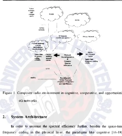
Nowadays. a multiplicity of radio access teclmology (RAT) standards are used in
"ireless communications. As shown in Figure ! .. these technologies can be rough!:
categorized in four sets:
• Cellular networks that include second-generation (2G) mobile systems. such as
Glohal s,stem for Mobile CommumcatlotlS CGSM)
Ill.
and their eYolutwns.olten called 2.:'iG s' stems. such as enhanced digital GSM eYolutwn (EDtil:.:).
General Packet Radio Access (GPRS) [2]. and IS 136m the US. These systems
are based on TDMA technology. Third generation (3G) mobile net\\ ori-s.
known as UniYersal Mobile Telecommunications Systems (UMTS) (WCDMA
and cdma2000)
f3l
are based on CDMA technology that proYides up to 2Mbit/s Llmg-term eYolution (l.TE) [4-121 0f these systems is e:x.pected ln
emlYe into 4G system providing up to 100 Mbit/s on the uplink and up to I
Gbit/s on the downlink. The solutions "·ill be based on a combination of
multtcarrier and space-time signal formats The network architectures include
macro. micro. and pico cellular networks and home (HAN) and personal area
network (PAN).
• Broadband radio access network (BRANs) [ 13] or wireless local area net" orks
(WLANs) [ 141 \Yhich are expected to provide up to l Gbit/s in 4G. These
teclmologies are based on OFDMA and space-time coding.
• Digital Yideo broadcasting (DVB) [151 and satellite conm1utlications. • Ad hoc and sensor networks with emerging applications
lOX
1
A SURVEY ON -IU NETWORKS ANIJ COMPOSITE RAIJlO ENVIRONMENT Banu W Yohanes
'kRS(lf
tl('l\\'tXb
!:<elf
\."\>(tll£UK ;.t<klfl)
Adh<.:
m:tu·nri;:-.
s....,..J_
(J4'!1Ul"'M')'
<od.&nr;t
llflliMIJJ
ウ。セ\@ II lie
f"ellular • Netwvrk
nwhklfl R".,;ontiguration
..,_t
&N|セ@ flytntmit:
IJVH
SJ!C<·Ira AltocJnloa
Rcronii$1Jr.:oi>IC
mセャ「ヲエ」t・ゥュゥaゥゥィ@
セcョヲエセ、ャゥセᄋ」L@ Ctlllp!r.dh-t·
ャャャャ、orBGヲャ||セゥウャャ\j@
IIRAI'<I
WI.AN/If1<5ll
/
セセMMfrrqvocy エBooZiョセ@/ tiGMtJ
[image:2.1054.75.470.67.508.2]I
Figure J. Composite radio emironment in cogtlitive. cooperative. and opp01tunistic
4G networks.
2.
System Architecture
In order to increase the spectral efficiency furtheL besides the space.fime
frequency coding in the physical layer, the paradigms like cognithe ( l6-18J.
cooperative {19-21]. and opportunistic [22-241 solutions \viii be used.
Although 4G 1s open for ne" multiple access schemes. the CRE concept
remains attractive for increasing the serrice provision efficiency and the exploitation
possibilities of the m·ailable RATs. The main assumption is that the different radio
networks. GPRS. UMTS. BRAN/WLAN. DVB. and so on. can be components of
a
heterogeneous wireless access infrastucture. A net\vork provider (NP) can 0\\11
several components of the CR infrastructure (in other \Yords. can own licenses for
deploYing and operating different RATs). and can also cooperate "ith affiliated NPs
In 。ョセ@ case. an NP can reh on se,·eral alternate radio net\vorks and technologies. for
Techne Jurnal Umiah Elektroteknika Vol. 1
) No.2 Oktober 2010 Hal 107 123
Nowadays. a multiplicity of radio access teclmology (RAT) standards are used in
"ireless communications. As shown in Figure ! .. these technologies can be rough!:
categorized in four sets:
• Cellular networks that include second-generation (2G) mobile systems. such as
Glohal s,stem for Mobile CommumcatlotlS CGSM)
Ill.
and their eYolutwns.olten called 2.:'iG s' stems. such as enhanced digital GSM eYolutwn (EDtil:.:).
General Packet Radio Access (GPRS) [2]. and IS 136m the US. These systems
are based on TDMA technology. Third generation (3G) mobile net\\ ori-s.
known as UniYersal Mobile Telecommunications Systems (UMTS) (WCDMA
and cdma2000)
f3l
are based on CDMA technology that proYides up to 2Mbit/s Llmg-term eYolution (l.TE) [4-121 0f these systems is e:x.pected ln
emlYe into 4G system providing up to 100 Mbit/s on the uplink and up to I
Gbit/s on the downlink. The solutions "·ill be based on a combination of
multtcarrier and space-time signal formats The network architectures include
macro. micro. and pico cellular networks and home (HAN) and personal area
network (PAN).
• Broadband radio access network (BRANs) [ 13] or wireless local area net" orks
(WLANs) [ 141 \Yhich are expected to provide up to l Gbit/s in 4G. These
teclmologies are based on OFDMA and space-time coding.
• Digital Yideo broadcasting (DVB) [151 and satellite conm1utlications. • Ad hoc and sensor networks with emerging applications
lOX
1
A SURVEY ON -IU NETWORKS ANIJ COMPOSITE RAIJlO ENVIRONMENT Banu W Yohanes
'kRS(lf
tl('l\\'tXb
!:<elf
\."\>(tll£UK ;.t<klfl)
Adh<.:
m:tu·nri;:-.
s....,..J_
(J4'!1Ul"'M')'
<od.&nr;t
llflliMIJJ
ウ。セ\@ II lie
f"ellular • Netwvrk
nwhklfl R".,;ontiguration
..,_t
&N|セ@ flytntmit:
IJVH
SJ!C<·Ira AltocJnloa
Rcronii$1Jr.:oi>IC
mセャ「ヲエ」t・ゥュゥaゥゥィ@
セcョヲエセ、ャゥセᄋ」L@ Ctlllp!r.dh-t·
ャャャャ、orBGヲャ||セゥウャャ\j@
IIRAI'<I
WI.AN/If1<5ll
/
セセMMfrrqvocy エBooZiョセ@/ tiGMtJ
[image:3.1054.75.470.67.508.2]I
Figure J. Composite radio emironment in cogtlitive. cooperative. and opp01tunistic
4G networks.
2.
System Architecture
In order to increase the spectral efficiency furtheL besides the space.fime
frequency coding in the physical layer, the paradigms like cognithe ( l6-18J.
cooperative {19-21]. and opportunistic [22-241 solutions \viii be used.
Although 4G 1s open for ne" multiple access schemes. the CRE concept
remains attractive for increasing the serrice provision efficiency and the exploitation
possibilities of the m·ailable RATs. The main assumption is that the different radio
networks. GPRS. UMTS. BRAN/WLAN. DVB. and so on. can be components of
a
heterogeneous wireless access infrastucture. A net\vork provider (NP) can 0\\11
several components of the CR infrastructure (in other \Yords. can own licenses for
deploYing and operating different RATs). and can also cooperate "ith affiliated NPs
In 。ョセ@ case. an NP can reh on se,·eral alternate radio net\vorks and technologies. for
Techne Jurnal flmiah Elebroteknika Vol. 9 No.2 Oktober 2010 Hal 107 123
achienng the reqmred capacity and QoS levels. in a cost-efficient manner Users are
directed to the most appropriate radio networks and technologies. at different sernce
area regions and time zones of d1e 、。セN@ based on profile requirements and network
performance cnteria. The various RATs are thus used in a 」ッューャ・ュ・ョエ。イセ@ manner n1ther than competing each other. EYen no" adan a mobile handset can make a
handoff beh,·een different RATs The deployment of CRE S\ stems can be facilitated
by the recontigurahility concept. which is an evolution of a soft"are-defined radio
[25. 261. The CRE requires terminals that are able to "ork mth different RATs. <md
the existence of multiple radio net\\ orks offering alternate "ireless access
capabilities to sen ice area regions. Reconfigurability supports the CRE concept by
prO\ 1d111g essenttal technologies that enable terminals and network element<:
dynamtcally (transparently and securely) to select and adapt to the set of RATs that
are most appropriate for the conditions encotmtered in specific sen·ice area regions
and time zones of the 、。セᄋ@ According to the reconfigurability concept. RAT selection
is not restricted to those that are pre-installed in the network element In fact the
required software components can be dynamically domlloaded. installed. and
Yalidated. Tllis makes it different from the static paradigm regarding the capabilities
of terminals and neh\ ark elements.
The networks proYide wireless access to IP (Internet protocols)-based
applications and sen ice continuity in the light of infrasystem mobility. Integration of
d1e network segments in the CR in1:l"astructure is acllieYed through the management system for the CRE (MS-CRE) components attached to each net\York. The
manaoement sYstem in each network manages a specific radio teclmology bo" eYer.
""
.the platforms can cooperate The fi'i.ed (core and bacl,bone) net\YOrk will consist of
public and primte segments based on lpY4- and lp\6-based infrastructures A mobile
IP (MIP) "·ill enable the mamtenance of IP-le\el cotmecll\ ゥエセ@ regardless of the likel:
changes in the underlying radio technologies used that will be imposed by the CRE
」ッョ」セエN@
I
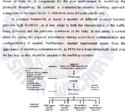
Figures 2 and 3 depict the architecture of a ternunal that is capable of
operating in n CRE context The terminals include soft\Yare and hard" are
components (layer l and 2 functionalities) for operating \Yith different system The
higher protocol layers. in accordance with their peer entities in the net" ork. support
I l ()
A SURVEY ON -Ill NETWORKS ANO COMPOSITE RADIO ENVIRONMENT Banu W Yohanes
continuous access to IP-based applications. Different protocol busters can further
enhance the efficiency of the protocol stack. There is a need to pro,ide the best
possible IP perfonnace owr wireless links. including legacy ウセ@ stems. Within the
performance implications of link characteristics (PILC) and the IETF group. the
concept of a performance-enhancing pro'-.:Y (PEP) 127-301 has been chosen to refer to
a set of methods used to unproYe the perfornumce of Internet protocols on net\,ork
paths "here natiYe TCP/IP performance is degraded due to characteristics of a link.
Different types of PEPs. depending on their basic functi01ling. are also dtstinguished.
Some of them try to compensate for the poor performance by modif)-ing the
protocols themselYes. In contrast a symmetric/asymmetric boosting approach.
transparent to the upper layers. is often both more efficient and flexible
A common frame\York to house a number of different protocol boosters
proYides high t1exibility. as it may adapt to both the characteristics of the traffic
being deli,ered and the particular conditions of the links. In thts sense. a control
plane for easing the required information sharing (cross-layer commwlication and
configmability) is needed. Furthermore. anotl1er requirement comes from the
appearance of multihop communications. as PEPs haYe been traditionally used mer
the last hop. so they should be adapted to the multihop scenario.
rcm1\nal ュ。イオZセョエ@
;;;y!itcrn
-• Ncl\1/ltrk dis:covt.·ry ,JUp:JXlf'l • NctYtx}f'\ sck:ctioo
• Mobility m ... セMNNQ@
inlotl<)'Jilem lvctlkall
-handovcr
• セゥゥ@ monitoring
• Prufile ュ。ョセァ・ュ」イイエ@ t1SC'·f ーイM」ヲl\^イ・QkセcsN@
tctmin:od char.K1L-ristics
if
handw1dtll
CI'RS""l'P'"'
イイZ。ウjセヲutャcョエ@
""""''"'
laJ"-r.< 211
Application eセ@ for TMS ゥョセ・イ。」エゥッッ@ and
lofnrmation fltw.· l<)'ndmmit..alion
1
TCJ>IIJI)P
1
rl
1
r
I
l'MTS Sllf'f'Url WLANIIJitAN f"'l''<"' Suppott ptoi<Mll
l.a)'<n 211 !.aye.-. 2/1
I'""'''''' I
hfx)!tlcrs & L'nnwn;ton
1
1
l>VIl-T
Support proiOcol lay!.'" :111
Figure 2 Architecture of a terminal that operates in a composite radjo emiromnent.
[image:4.1053.72.471.240.598.2]Techne Jurnal flmiah Elebroteknika Vol. 9 No.2 Oktober 2010 Hal 107 123
achienng the reqmred capacity and QoS levels. in a cost-efficient manner Users are
directed to the most appropriate radio networks and technologies. at different sernce
area regions and time zones of d1e 、。セN@ based on profile requirements and network
performance cnteria. The various RATs are thus used in a 」ッューャ・ュ・ョエ。イセ@ manner n1ther than competing each other. EYen no" adan a mobile handset can make a
handoff beh,·een different RATs The deployment of CRE S\ stems can be facilitated
by the recontigurahility concept. which is an evolution of a soft"are-defined radio
[25. 261. The CRE requires terminals that are able to "ork mth different RATs. <md
the existence of multiple radio net\\ orks offering alternate "ireless access
capabilities to sen ice area regions. Reconfigurability supports the CRE concept by
prO\ 1d111g essenttal technologies that enable terminals and network element<:
dynamtcally (transparently and securely) to select and adapt to the set of RATs that
are most appropriate for the conditions encotmtered in specific sen·ice area regions
and time zones of the 、。セᄋ@ According to the reconfigurability concept. RAT selection
is not restricted to those that are pre-installed in the network element In fact the
required software components can be dynamically domlloaded. installed. and
Yalidated. Tllis makes it different from the static paradigm regarding the capabilities
of terminals and neh\ ark elements.
The networks proYide wireless access to IP (Internet protocols)-based
applications and sen ice continuity in the light of infrasystem mobility. Integration of
d1e network segments in the CR in1:l"astructure is acllieYed through the management system for the CRE (MS-CRE) components attached to each net\York. The
manaoement sYstem in each network manages a specific radio teclmology bo" eYer.
""
.the platforms can cooperate The fi'i.ed (core and bacl,bone) net\YOrk will consist of
public and primte segments based on lpY4- and lp\6-based infrastructures A mobile
IP (MIP) "·ill enable the mamtenance of IP-le\el cotmecll\ ゥエセ@ regardless of the likel:
changes in the underlying radio technologies used that will be imposed by the CRE
」ッョ」セエN@
I
Figures 2 and 3 depict the architecture of a ternunal that is capable of
operating in n CRE context The terminals include soft\Yare and hard" are
components (layer l and 2 functionalities) for operating \Yith different system The
higher protocol layers. in accordance with their peer entities in the net" ork. support
I l ()
A SURVEY ON -Ill NETWORKS ANO COMPOSITE RADIO ENVIRONMENT Banu W Yohanes
continuous access to IP-based applications. Different protocol busters can further
enhance the efficiency of the protocol stack. There is a need to pro,ide the best
possible IP perfonnace owr wireless links. including legacy ウセ@ stems. Within the
performance implications of link characteristics (PILC) and the IETF group. the
concept of a performance-enhancing pro'-.:Y (PEP) 127-301 has been chosen to refer to
a set of methods used to unproYe the perfornumce of Internet protocols on net\,ork
paths "here natiYe TCP/IP performance is degraded due to characteristics of a link.
Different types of PEPs. depending on their basic functi01ling. are also dtstinguished.
Some of them try to compensate for the poor performance by modif)-ing the
protocols themselYes. In contrast a symmetric/asymmetric boosting approach.
transparent to the upper layers. is often both more efficient and flexible
A common frame\York to house a number of different protocol boosters
proYides high t1exibility. as it may adapt to both the characteristics of the traffic
being deli,ered and the particular conditions of the links. In thts sense. a control
plane for easing the required information sharing (cross-layer commwlication and
configmability) is needed. Furthermore. anotl1er requirement comes from the
appearance of multihop communications. as PEPs haYe been traditionally used mer
the last hop. so they should be adapted to the multihop scenario.
rcm1\nal ュ。イオZセョエ@
;;;y!itcrn
-• Ncl\1/ltrk dis:covt.·ry ,JUp:JXlf'l • NctYtx}f'\ sck:ctioo
• Mobility m ... セMNNQ@
inlotl<)'Jilem lvctlkall
-handovcr
• セゥゥ@ monitoring
• Prufile ュ。ョセァ・ュ」イイエ@ t1SC'·f ーイM」ヲl\^イ・QkセcsN@
tctmin:od char.K1L-ristics
if
handw1dtll
CI'RS""l'P'"'
イイZ。ウjセヲutャcョエ@
""""''"'
laJ"-r.< 211
Application eセ@ for TMS ゥョセ・イ。」エゥッッ@ and
lofnrmation fltw.· l<)'ndmmit..alion
1
TCJ>IIJI)P
1
rl
1
r
I
l'MTS Sllf'f'Url WLANIIJitAN f"'l''<"' Suppott ptoi<Mll
l.a)'<n 211 !.aye.-. 2/1
I'""'''''' I
hfx)!tlcrs & L'nnwn;ton
1
1
l>VIl-T
Support proiOcol lay!.'" :111
Figure 2 Architecture of a terminal that operates in a composite radjo emiromnent.
[image:5.1053.72.471.240.598.2]Techne Jurnalllmiah Eleltroteknikn Vol. 4 No. 2 Ol.."tober 2010 Hull07- 123
AJII'Ilcallml
- "-<ldfarTM!i - A I P
GQ|Gュャャャャャャセ@
s, ...
• ,....1 _ _ _ , Ulppo<l
• 1\.'<lwarl ..,lb:lloo -I
-• wLN ャャI[ヲNョゥQセ uエsャAwi@ i:l)lflltUfAil !io
• セセセャヲゥAdヲ@ イョセGwGエャ@ n
lnfnml:dUI !Ioiii ndUDIIIulloo
I
TC MlOP
1
IP, J.I<JNk IP
l
QヲィBセセ@ |NG| Gャヲゥ|pセ GQ u IiN@ h'f" aJm1TIUttk1111! .. セセエョ ᄋ@.. セ セ@
.. 11:11 ,
Figure 3. Architecture of a terminal that operates in the reconfigurability context
Most communicatjons networks are subj ect to time and regional \-aria.tions in
traffic demands. which lead to nlfiations in the degree to which the spectrum is utilized. Therefore, a service's radio spectrum can be underused at certain times or geographical areas. while another sen·ice may experience a shortage at the same time/place Giyeo the Jugh economic Yalue placed on the radio spectrum and the
importance of spectrum efficiency. it is dear that wastage of radio spectrum must be
a\'oided.
These issues pro'fide the moth·ation for a scheme called
dynantic spectnuu allocation (DSA. wlucb aims to manage the spectrum utilized by a conYerged radiosystem and share it bet\ -een participating rad io networks oYer space and time to
increase oYernll spectrum efficiency. as shoml in Figures 4. and 5.
Composite radio systems and rec<>nfigurabilit. ·. discussed abm·e. are potential
enablers of DSA systems. C roposite radio systems allow seamless deli,·ery of
sen·ices through the most appropriate access network. and close nehYork cooperation
can facilitate the sharing not only senices but also spectmm. Reconfigurability is
ョャウッ セ Gャ@ ,-ery important issue. since with a DSA system a radio access network could
potentially be allocated any frequency ut am· time in ru.1y location. It should be noted that the application layer is enhanced with the means to S) n hronize ·arious
Jl2
A SURVEY ON ..IG NETWORKS AND COMPOSITE RADIO ENVIRONMENT
Banu W. Yohanes
information st reams of the same application. which could be transported
sinmltaneously oYer different RATs.
f.•I X(d cセGャャャゥセMNオNセ@
セ@ 2 "'
...
§
l
セ@
:2l. z<
:i
セ@ セ@ 1:11v
I r.• r1
セ@
i セ@
セ@
3
セ@
"'
!
lril I
1--J-セ M
1--I
i
セ@
I
セ@ z
セ@
zセ@ セ@ < at: :i
I - J-
f-1-· L-A
I--,..._
M セNセ@
1I
-セ@ -セ@ -セ@
セ@
-i ""
:0:セ@
[image:6.1051.72.441.176.544.2]'lime I)( イ」セゥ\wi@
Figure 4. Fixed spectrum allocation compared to contjguous and fragmented DSA.
I I j
i
0 I
..
i
i
lcl
Figure 5. DSA operation configurations : (a) static (current spectrum allocations): (b)
continuous DSA operations: (c) discrete DSA operations.
The termin. I mnnag ment sys tem (TMS) is essential for pronding
funclionaUty that xploits lh CR em ironment. On the user/terminal side, the main
Techne Jurnalllmiah Eleltroteknikn Vol. 4 No. 2 Ol.."tober 2010 Hull07- 123
AJII'Ilcallml
- "-<ldfarTM!i - A I P
GQ|Gュャャャャャャセ@
s, ...
• ,....1 _ _ _ , Ulppo<l
• 1\.'<lwarl ..,lb:lloo -I
-• wLN ャャI[ヲNョゥQセ uエsャAwi@ i:l)lflltUfAil !io
• セセセャヲゥAdヲ@ イョセGwGエャ@ n
lnfnml:dUI !Ioiii ndUDIIIulloo
I
TC MlOP
1
IP, J.I<JNk IP
l
QヲィBセセ@ |NG| Gャヲゥ|pセ GQ u IiN@ h'f" aJm1TIUttk1111! .. セセエョ ᄋ@.. セ セ@
.. 11:11 ,
Figure 3. Architecture of a terminal that operates in the reconfigurability context
Most communicatjons networks are subj ect to time and regional \-aria.tions in
traffic demands. which lead to nlfiations in the degree to which the spectrum is utilized. Therefore, a service's radio spectrum can be underused at certain times or geographical areas. while another sen·ice may experience a shortage at the same time/place Giyeo the Jugh economic Yalue placed on the radio spectrum and the
importance of spectrum efficiency. it is dear that wastage of radio spectrum must be
a\'oided.
These issues pro'fide the moth·ation for a scheme called
dynantic spectnuu allocation (DSA. wlucb aims to manage the spectrum utilized by a conYerged radiosystem and share it bet\ -een participating rad io networks oYer space and time to
increase oYernll spectrum efficiency. as shoml in Figures 4. and 5.
Composite radio systems and rec<>nfigurabilit. ·. discussed abm·e. are potential
enablers of DSA systems. C roposite radio systems allow seamless deli,·ery of
sen·ices through the most appropriate access network. and close nehYork cooperation
can facilitate the sharing not only senices but also spectmm. Reconfigurability is
ョャウッ セ Gャ@ ,-ery important issue. since with a DSA system a radio access network could
potentially be allocated any frequency ut am· time in ru.1y location. It should be noted that the application layer is enhanced with the means to S) n hronize ·arious
Jl2
A SURVEY ON ..IG NETWORKS AND COMPOSITE RADIO ENVIRONMENT
Banu W. Yohanes
information st reams of the same application. which could be transported
sinmltaneously oYer different RATs.
f.•I X(d cセGャャャゥセMNオNセ@
セ@ 2 "'
...
§
l
セ@
:2l. z<
:i
セ@ セ@ 1:11v
I r.• r1
セ@
i セ@
セ@
3
セ@
"'
!
lril I
1--J-セ M
1--I
i
セ@
I
セ@ z
セ@
zセ@ セ@ < at: :i
I - J-
f-1-· L-A
I--,..._
M セNセ@
1I
-セ@ -セ@ -セ@
セ@
-i ""
:0:セ@
[image:7.1051.72.441.176.544.2]'lime I)( イ」セゥ\wi@
Figure 4. Fixed spectrum allocation compared to contjguous and fragmented DSA.
I I j
i
0 I
..
i
i
lcl
Figure 5. DSA operation configurations : (a) static (current spectrum allocations): (b)
continuous DSA operations: (c) discrete DSA operations.
The termin. I mnnag ment sys tem (TMS) is essential for pronding
funclionaUty that xploits lh CR em ironment. On the user/terminal side, the main
Technc Jurnal Ihniah Elektroteknika Vol.') No.2 Oktober 2010 Hall07- l23
focus is on the determination of the networks that proYide. in a cost-efficient manner.
the best QoS leYels for the set of actiYe applications. A llrst requirement is that the
MS-CRE should exploit the capabilities of the CR infrastructure Tllis can be done in
a reactiYe or proactiYe member.
ReactiYeh _ the MS-C'RE reacts to ne" sernce area conditions. such as the
unexpected emergence of hot spots. Proactiwly. the management s' stem can
anticipate changes in the demand pattern. Such situations can be aile' iated 「セ@ using
alternate components of the CR infrastructure to achieYe the required capaCity and
QoS leYels. The second requirement is that the MS-CRE should prm ide resource
brokerage functionality to enable the cooperation of the net\Yorks of the CR
mfrastucture. fゥョ。ャャセN@ parts of the MS-CRE should be capable of dtrecting users to
the most appropriate networks of the CR infrastucture. "·here they will obtain
sen·ices efficiently in terms of cost and QoS. To achieYe the abm e requirements the
MS architecture shom1 in Ftgure 6. is required
The architecture consists of tluee main logical entities:
• Monitoring. serYice-lewl information and resource brokerage (MSRB).
• Resource management strategies (RMS ).
• Session managers (SMs).
mョセゥォ@ (::·.)
h:rm1rwtl
ll..:.:r.mJ セNッッQイLIャ@ イャセMLGャLN@ lnh' イヲZセNZLG@
Managed uctwUfk (compnrh:nl nf CR
infr.aslftKiurd-エL」セュNZケ@ ch:mcl\1: 11nd JK1worl manag..:mcnt ZゥケセエHGャQ「@
ヲゥNセイオイ・@ () Architecture of the MS-CRE
l ] .. f
A SURVEY ON -lfi NETWORK.\' AND COMPOSITE RADIO ENVJRONMENT
Banu W Yohancs
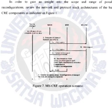
The MSRB entity identifies the triggers (eYents) that should be handled by the
MS-CRE and proYides corresponding auxiliary (supporting) functionality. The RMS
entity prm·ides the necessary optimization functionality. The SM entity is in charge
of interacting "ith the actiYe subscribed user/ternlinals. The operations steps and
cooperation of the RMS components are shom1 in Ftgures 7 and X . respecri' eh
In order to gain an insight mto the scope and range of possible
reconfigurations. reYie'' the net" ork and protocol stack architectures of the basic
CRE components as indicated in Figure 1.
s」セセゥゥョャ@
oI[ャョセNNZイ@
I
I il.kn Ufil':II.H>n or m;v.c
'-"lmdilion in ウ」ョゥlGセ@ &KC.t
MStB RMS
2. eセエイ。、ゥッョ@ of .Qa.lu" uf
Nctworl< and ol SLA>
"""'· l.:klerminatiOn nr nt.·w
:-;ern(.-..:- pn.l'f'b:ion pau.:m (f.)oS
ャ・カ・ャセN@ 1raflk 、ィオゥセオエャッョ@ ttl network:§;•
Complllutton of
Tc-ntall\'e イッ」ッゥ|cゥァオイ。エゥッョZセ@
I
5. S.!lutklll
"""'·l'l•""'
phnsc. R«."<lllllgutnlloo ol managedrkLwtrt and ュ[オQ。ァセNNセ@ セクュ。ーッッ」ョエZウ@
I
mNセNcre@
Figure 7. MS-CRE operation scenario.
[image:8.1051.71.454.180.549.2]Technc Jurnal Ihniah Elektroteknika Vol.') No.2 Oktober 2010 Hall07- l23
focus is on the determination of the networks that proYide. in a cost-efficient manner.
the best QoS leYels for the set of actiYe applications. A llrst requirement is that the
MS-CRE should exploit the capabilities of the CR infrastructure Tllis can be done in
a reactiYe or proactiYe member.
ReactiYeh _ the MS-C'RE reacts to ne" sernce area conditions. such as the
unexpected emergence of hot spots. Proactiwly. the management s' stem can
anticipate changes in the demand pattern. Such situations can be aile' iated 「セ@ using
alternate components of the CR infrastructure to achieYe the required capaCity and
QoS leYels. The second requirement is that the MS-CRE should prm ide resource
brokerage functionality to enable the cooperation of the net\Yorks of the CR
mfrastucture. fゥョ。ャャセN@ parts of the MS-CRE should be capable of dtrecting users to
the most appropriate networks of the CR infrastucture. "·here they will obtain
sen·ices efficiently in terms of cost and QoS. To achieYe the abm e requirements the
MS architecture shom1 in Ftgure 6. is required
The architecture consists of tluee main logical entities:
• Monitoring. serYice-lewl information and resource brokerage (MSRB).
• Resource management strategies (RMS ).
• Session managers (SMs).
mョセゥォ@ (::·.)
h:rm1rwtl
ll..:.:r.mJ セNッッQイLIャ@ イャセMLGャLN@ lnh' イヲZセNZLG@
Managed uctwUfk (compnrh:nl nf CR
infr.aslftKiurd-エL」セュNZケ@ ch:mcl\1: 11nd JK1worl manag..:mcnt ZゥケセエHGャQ「@
ヲゥNセイオイ・@ () Architecture of the MS-CRE
l ] .. f
A SURVEY ON -lfi NETWORK.\' AND COMPOSITE RADIO ENVJRONMENT
Banu W Yohancs
The MSRB entity identifies the triggers (eYents) that should be handled by the
MS-CRE and proYides corresponding auxiliary (supporting) functionality. The RMS
entity prm·ides the necessary optimization functionality. The SM entity is in charge
of interacting "ith the actiYe subscribed user/ternlinals. The operations steps and
cooperation of the RMS components are shom1 in Ftgures 7 and X . respecri' eh
In order to gain an insight mto the scope and range of possible
reconfigurations. reYie'' the net" ork and protocol stack architectures of the basic
CRE components as indicated in Figure 1.
s」セセゥゥョャ@
oI[ャョセNNZイ@
I
I il.kn Ufil':II.H>n or m;v.c
'-"lmdilion in ウ」ョゥlGセ@ &KC.t
MStB RMS
2. eセエイ。、ゥッョ@ of .Qa.lu" uf
Nctworl< and ol SLA>
"""'· l.:klerminatiOn nr nt.·w
:-;ern(.-..:- pn.l'f'b:ion pau.:m (f.)oS
ャ・カ・ャセN@ 1raflk 、ィオゥセオエャッョ@ ttl network:§;•
Complllutton of
Tc-ntall\'e イッ」ッゥ|cゥァオイ。エゥッョZセ@
I
5. S.!lutklll
"""'·l'l•""'
phnsc. R«."<lllllgutnlloo ol managedrkLwtrt and ュ[オQ。ァセNNセ@ セクュ。ーッッ」ョエZウ@
I
mNセNcre@
Figure 7. MS-CRE operation scenario.
[image:9.1051.71.454.180.549.2]Technc Jurnnl Tlmiah Elcktroteknika Vol. l) No.2 Oktober 2010 Hal107 -123
MSIUI lroffic di!ilriOUIIUil セヲ|ᄋゥ」」@ 」LュヲャLAAuイセャゥ|GB@
2. Sc.rv-icco configurru.ion :Uld Lr.allic distnbution:
aャィセ。Nャゥッョ@ to (.)o." :tnd Jll'tu.'{tfb.
4. Sdoclion l,f hcst
Fea.'i ib".: :-.ol ut ion
"\h. ('ompuhninn tll
1'..:-utativL n<:Cwork n .. "Configuration
7. Network 」ョョャゥセオ」。エエオョ@
FigureR. Cooperation of the RMS components.
3.
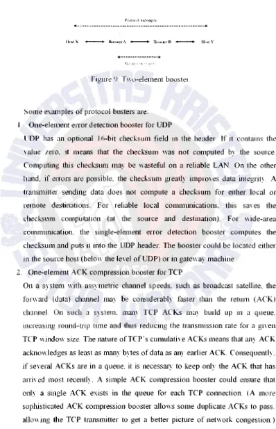
Protocol Boosters Analysis
As pointed out in Figure 2 .. an element of the reconf1guration in 4G nen,orks
are protocol boosters. A protocol boosters is a soft,yare or hardware module that
trmlsparently improYes protocol performance. The booster cm1 reside any" here in the
net" ork or end systems. and may operate independently (one-element booster) or m
cooperation "·ith other protocol boosters (multielement booster). Protocol boosters
proYide ru1 architectural alternatiYe to existing protocol adaptation techniques. such
as protocol com ersion
A protocol booster 1s a supporting agent that by 1tself is not a protocol lt ュ。セ@
dd delete or delaY protocol messages. but neYer originates. terminates. or com ert
a セM - .
that protocol. A multielement protocol booster ュ。セ@ define ne" protocol messages to
exchange among then1Se1Yes. but these protocols are originated and terminated
「セ@
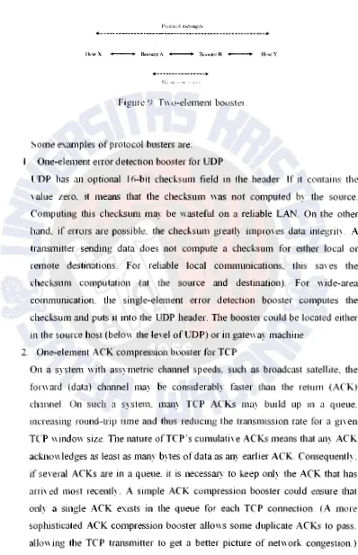
prot [image:10.1055.73.471.81.698.2]9
col booster elements. and are not Yisible or mem1ingful external to the boosterFigure !J sho" s the information flo" in a generic t" o-element booster A protocol
:H'c)>k' t:trt:p:u·t:·11! \(' 1hc protocol being boosted Thus the elimination of a
pr,llCic,d bc;c,stcr \\ill nn1 prE"·ent end-tn-end communication. as would. for example.
the renH•\;1! of' cme エセョ、@ nf ZMセ@ cotwersinn (e g a TCP/IP header compression unit)
A SURVEY ON .J(i NETWORKS AND COMPO.\'ITE RADIO ENVIRONMENT
Banu W Yohanes
セQヲN[ャゥ|k|ii@ ャャィNZGI[セZjiAA|NGZ^N@
... -... ________ --- ... ---+
... ll I ' セセ@ i ._ ! 'll, ' ' セi@'' ''
Figure '0 T\\ o-element booste1
Some exrunp1es of protocol busters are:
1. One-element error detection booster for UDP
UDP has an optional 16-bit checksum field in the header If it contains the
' alue zero. it means that the checksum was not computed by the source.
Computing this checksum may be wasteful on a reliable LAN. On the other
hand. if errors are possibk. the checksum greatly improYes data integritY. A
transmitter sending data does not compute a checksum for either local or
remote destinations. For reliable local communications, this saYes the
checksum computation (at the source and destination). For "ide-area
communication. the single-element error detection booster computes the
checksum and puts it into the UDP header. The booster could be located either
in the source host (below the leYel of UDP) or in gate"·ay machine.
2. One-element ACK compression booster for TCP
On a system "·ith assymetric chmmel speeds. such as broadcast sate11ite. the
fom m·d (data) chrumel ュ。セ@ be COI1SJderably faster than the return (ACK)
channel On such a system. many TCP ACKs may bwld up m a queue.
inneasing round-trip time and thus reducing the transmission rate for a giYen
TCP windmY size. The nature ofTCP's cumulatiYe ACKs means that any ACK
ackno" ledges as least as many b)1es of data as any earlier ACK Consequently.
if seYeral ACKs are in a queue. it is necessm)· to keep only the ACK that has
arriYed most recently. A simple ACK compression booster could et1Sure that
only a single ACK exists in the queue for each TCP connection. (A more
sophisticated ACK compression booster allo"·s some duplicate ACKs to pass.
allo"ing the TCP transmitter to get a better picture of net"·ork congestion.)
Tcclme Jurnal JJmiah Elcktroteknika Vol. 'J No 2 Oktober 2010 Hal 107- 123
3.
4.
The booster increases the protocol performance because it reduces the ACK
latency and allmYs faster transmission for a giYen "indow size.
One-element congestion control booster for TCP
Congestion control reduces buffer oYerflo\\ loss 「セᄋ@ reducing the transmission
r:Jt<:' at the source ,,hen the ョ・セLMッイォ@ is congested. A TCP transmitter deduces information about net\\ork congestion by exammmg ackno\\ledgments (ACKs)
sent by the TCP receiYer If the transmitter sees se,·eral AC Ks "ith the same
sequence number. then it assumes that network congestion caused a loss of data
messages. If congestion is noted in a subnet. then a control booster could
artificially produce duplicate ACK.s. The TCP receiver \Yould think that data
messages haYe been lost because of congestion. and "ould reduce its "indo"
size. thus reducing the amount of data it injects into the net\YOrk.
One-element ARQ booster for TCP
TCP uses ARQ to retransmit data unacknowledged by the receiYer "hen a
packet loss is suspected. such as after a retransmission timeout expires.
Assuming the net\York of Figure 9. (except that Booster B does not exist). then
an ARQ booster for TCP will:
a) cache packets from Host Y:
b) if it sees a duplicate acknowledgment arriYe from Host X and it has the next
packet in the cache. then it deletes the acknowledgment and retransmits the
next packet (because a packet must haYe been lost behYeen the booster and
Host X):
c) delete packets retransmitted from Host Y that haYe been ackno" I edged 「セ@
Host X
The ARQ booster improYes performance by shortening the retransmission path
A typical application "ould be if Host X "ere on a wireless net"ork and the
booster were on the interface bet\Yeen the ''ireless and wireline nehYorks.
5.
f
A forward erasure correction booster for IP or TCP!IR
For mm1y real time and multicast applications. fonYard error correction coding
1s desirable. The t" o-element FZC booster uses a packet fom ard error
correction code and erasure decoding. The FZC booster at the transmitter side
6.
7.
A SURVEY ON .I(; NETWORKS AND COMPO.\'ITE RADIO ENVIRONMENT Bur111 W Yohuncs
of the network adds parity packets. The FZC booster at the receiYer side
remo,·es the parity packets and regenerates missing data packets. The FZC
booster can be applied bet\\ een any t\YO points in a net\York (including the end
systems). If applied to an IP. then a sequence number booster adds sequence
number information to the data packets before the first FZC booster Tf applied
to TCP (or any protocol "·ith sequence number information)_ then the FZC
booster can be more efficient because:
a 1 it does not need to add sequence numbers.
b1 it could add ne" parity information on TCP retrm1smission (rather than
repeating the same parities)_
At the receiYer side. the FZC booster could combine information from multiple
TCP retransmissions for FZC decoding.
Two-element jitter control booster for IP
For real time communications. we may be mterested in bounding the mnount of
jitter that occurs in the nenvork. A jitter control booster cm1 be used to reduce
jitter at the expense of increased latency. At the first booster element the
timestamps m·e generated for each data message that passes. These timestamps
are transmitted to the second booster element. which delays messages and
attempts to reproduce the intermessage interyal that \Yas measured by the first
booster element.
T\YO-element selectiYe ARQ booster for IP or TCP
For links with significant errors rate using a selectiw ARQ protocol (\Yith
seiectiYe acknmdedgment and selectiYe retransmission) can ウゥァョゥヲゥ」。ョエAセ@
imprm e the efficiency compared to using Tcp· s ARQ (\\ ith cumulatiYe
ackt1o" ledgment and possibly go-back-N retransmission) The two element
ARQ booster uses a selecti' e ARQ booster to supplement TCP by
a) caching packets in the upstream booster.
b) sending negati Ye acknowledgments when gaps are detected in the
do\\nstream booster.
c) selecliYely retrm1smitting the packet requested m the negatiYe
Technc Jurnnl Tlmiah Elcktroteknika Vol. l) No.2 Oktober 2010 Hal107 -123
MSIUI lroffic di!ilriOUIIUil セヲ|ᄋゥ」」@ 」LュヲャLAAuイセャゥ|GB@
2. Sc.rv-icco configurru.ion :Uld Lr.allic distnbution:
aャィセ。Nャゥッョ@ to (.)o." :tnd Jll'tu.'{tfb.
4. Sdoclion l,f hcst
Fea.'i ib".: :-.ol ut ion
"\h. ('ompuhninn tll
1'..:-utativL n<:Cwork n .. "Configuration
7. Network 」ョョャゥセオ」。エエオョ@
FigureR. Cooperation of the RMS components.
3.
Protocol Boosters Analysis
As pointed out in Figure 2 .. an element of the reconf1guration in 4G nen,orks
are protocol boosters. A protocol boosters is a soft,yare or hardware module that
trmlsparently improYes protocol performance. The booster cm1 reside any" here in the
net" ork or end systems. and may operate independently (one-element booster) or m
cooperation "·ith other protocol boosters (multielement booster). Protocol boosters
proYide ru1 architectural alternatiYe to existing protocol adaptation techniques. such
as protocol com ersion
A protocol booster 1s a supporting agent that by 1tself is not a protocol lt ュ。セ@
dd delete or delaY protocol messages. but neYer originates. terminates. or com ert
a セM - .
that protocol. A multielement protocol booster ュ。セ@ define ne" protocol messages to
exchange among then1Se1Yes. but these protocols are originated and terminated
「セ@
prot [image:12.1055.73.471.81.698.2]9
col booster elements. and are not Yisible or mem1ingful external to the boosterFigure !J sho" s the information flo" in a generic t" o-element booster A protocol
:H'c)>k' t:trt:p:u·t:·11! \(' 1hc protocol being boosted Thus the elimination of a
pr,llCic,d bc;c,stcr \\ill nn1 prE"·ent end-tn-end communication. as would. for example.
the renH•\;1! of' cme エセョ、@ nf ZMセ@ cotwersinn (e g a TCP/IP header compression unit)
A SURVEY ON .J(i NETWORKS AND COMPO.\'ITE RADIO ENVIRONMENT
Banu W Yohanes
セQヲN[ャゥ|k|ii@ ャャィNZGI[セZjiAA|NGZ^N@
... -... ________ --- ... ---+
... ll I ' セセ@ i ._ ! 'll, ' ' セi@'' ''
Figure '0 T\\ o-element booste1
Some exrunp1es of protocol busters are:
1. One-element error detection booster for UDP
UDP has an optional 16-bit checksum field in the header If it contains the
' alue zero. it means that the checksum was not computed by the source.
Computing this checksum may be wasteful on a reliable LAN. On the other
hand. if errors are possibk. the checksum greatly improYes data integritY. A
transmitter sending data does not compute a checksum for either local or
remote destinations. For reliable local communications, this saYes the
checksum computation (at the source and destination). For "ide-area
communication. the single-element error detection booster computes the
checksum and puts it into the UDP header. The booster could be located either
in the source host (below the leYel of UDP) or in gate"·ay machine.
2. One-element ACK compression booster for TCP
On a system "·ith assymetric chmmel speeds. such as broadcast sate11ite. the
fom m·d (data) chrumel ュ。セ@ be COI1SJderably faster than the return (ACK)
channel On such a system. many TCP ACKs may bwld up m a queue.
inneasing round-trip time and thus reducing the transmission rate for a giYen
TCP windmY size. The nature ofTCP's cumulatiYe ACKs means that any ACK
ackno" ledges as least as many b)1es of data as any earlier ACK Consequently.
if seYeral ACKs are in a queue. it is necessm)· to keep only the ACK that has
arriYed most recently. A simple ACK compression booster could et1Sure that
only a single ACK exists in the queue for each TCP connection. (A more
sophisticated ACK compression booster allo"·s some duplicate ACKs to pass.
allo"ing the TCP transmitter to get a better picture of net"·ork congestion.)
Techne Jurnol Ilmiuh Elektroteknika Vol 9 No. 2 Oktober 20 l 0 Hal I 07 - 123
4. Discussion and further development
4
o wireless net\Yorks might be using a spatial notching (angle a) to suppress
completely antenna radiation to\Yards the user. as illustrated in Figure I o. These
solutions "ill be referred to as -green wireless networks- for ob\ious reasons ln
order to ensure the connectiYity Ill the case when alllt::HUil iuU...: i:> uu! uu NNZBBGL[セLL@ "·-'. '"
the access point a multihop conununication. "Ith the possibiht: of relayutg. b
required In addition. to reduce the oYerall transnul power a cooperati\ e transtmt
diYersity and adaptiYe medium access control {MAC) protocol can be used
\
' ).--.·."··.·.··.·. NゥセXゥ[Z@ '.,
lw 2
.
' .
"'"-
.MMセ@
( /· MLセ@.. セセ@
セNエG@
'l
[image:13.1054.69.467.87.719.2]1 Tl1l·ee-dtinensional amplitude patterns of a hYo-element umform
Figure IO .
amplitude array for d=2i,. directioned tO\Yards (a) 8o
=
o ·
lbJ8" = 60 :
2 Three-dimensional runplitude patterns of a ten-element uniform
f'.01- d=,'J4. directioned towards (a) ・セ@
-::-
o. (b)amplitude 。イイ。セ@
A SURVEY ON ./6' NETWORK/;' ANI> COMPO.\'TTE RA/JlO ENVIRONMENT Banu W Yolwnes
References
[I] M_ Mouh and M -8. Pautet. 1l1e GSM .\vstern fin- Mohilc CommJI/11('(//1011S.
Palaiseau. France. 1992.
[2} R. Kalden. I. Meirick. and M_ Meyer. Wireless Internet access based on GPRS.
!F/·T Pen f'nnm11111 \ol7 110 :?. April 2000. pp X-IX
1' 1 Sセ\ Q@ Generation Pm·tnership Project OGPPt http:/1\Y\\W 1gpp org
[4] P Mogensen. We1 Na. L Z KoYacs. F. Frederiksen. A Pokhari\ al. K I
Pedersen. T Kolding. K Hugl and M. Kuusela. L TE capacity compared to the
Sha1mon bound. in VehJcnlar Technolo:.;;y Con{. 22-25 April 2007. pp
1234-l23X.
[51 H Holma_ A Toskala. K Rantha-aho_ and J Pirskanen. H1gh-speed packet
access e\olution in 3GPP Release 7 {Topics in Radio Conununications]. IEEE Comnum Mag. Yol. 45. no. 12. December 2007. pp. 29-35 .
f6J A Hoikkanen. A techno-economic analysis of 3G long-term e\olution for
broadband access. in cPQセャ@ on Telecommun. Techno-Economics. 14-15 June 2007.pp. !-7.
[7] A Racz. A TemesYary. N. Reider. Hando\'er performance in 3GPP long term
eYolution (L TE) systems. in Mobile ru1d Wireless Commun. Summit 16th IST.
1-5 July 20tH. pp. l-5.
(8] M. Valkama. L Anttila and M_ Renfors. Some radio implementation challenges
in 3G-LTE context. in Signal Processing Adnnces in Wireless Conunun ..
UEE 8'1' Workshop on SPA WC 2007. 17-20 June. pp. 1-5
[9] J J. Sanchez. D. Morales-Jimenez. G Gomez and J. T Enbrambasaguas. PhYsical Layer performance of long term e-rolution m cellular technology. 111
J
r/"
JST A1ohile and Wireless Commun. Summit. J -5 July 2007. pp. l-5.[JO] J. Berkmam1. C. Carbonelli. F. Dietrich. C. Drewes. and Wen Xu. On 3G LTE
terminal implementation standards. algorithms. complexities. and challenges.
in Internal tonal Wireless Commun and Mobile Computing Conl!W'CA1C '08.
()-X August 200X. pp 970-975.
1111 C. Sp1egeL J Berkmann_ Zijian Ba'. T Scholand. and C Dre\\ es. MIMO schemes m UTRA L TE a comparison. in IEEE VehJculor rechnoloi:.l' Conl.
J J-14 Mm 2008. pp.222X-2232.
Tcclme Jurnal JJmiah Elcktroteknika Vol. 'J No 2 Oktober 2010 Hal 107- 123
3.
4.
The booster increases the protocol performance because it reduces the ACK
latency and allmYs faster transmission for a giYen "indow size.
One-element congestion control booster for TCP
Congestion control reduces buffer oYerflo\\ loss 「セᄋ@ reducing the transmission
r:Jt<:' at the source ,,hen the ョ・セLMッイォ@ is congested. A TCP transmitter deduces information about net\\ork congestion by exammmg ackno\\ledgments (ACKs)
sent by the TCP receiYer If the transmitter sees se,·eral AC Ks "ith the same
sequence number. then it assumes that network congestion caused a loss of data
messages. If congestion is noted in a subnet. then a control booster could
artificially produce duplicate ACK.s. The TCP receiver \Yould think that data
messages haYe been lost because of congestion. and "ould reduce its "indo"
size. thus reducing the amount of data it injects into the net\YOrk.
One-element ARQ booster for TCP
TCP uses ARQ to retransmit data unacknowledged by the receiYer "hen a
packet loss is suspected. such as after a retransmission timeout expires.
Assuming the net\York of Figure 9. (except that Booster B does not exist). then
an ARQ booster for TCP will:
a) cache packets from Host Y:
b) if it sees a duplicate acknowledgment arriYe from Host X and it has the next
packet in the cache. then it deletes the acknowledgment and retransmits the
next packet (because a packet must haYe been lost behYeen the booster and
Host X):
c) delete packets retransmitted from Host Y that haYe been ackno" I edged 「セ@
Host X
The ARQ booster improYes performance by shortening the retransmission path
A typical application "ould be if Host X "ere on a wireless net"ork and the
booster were on the interface bet\Yeen the ''ireless and wireline nehYorks.
5.
f
A forward erasure correction booster for IP or TCP!IR
For mm1y real time and multicast applications. fonYard error correction coding
1s desirable. The t" o-element FZC booster uses a packet fom ard error
correction code and erasure decoding. The FZC booster at the transmitter side
6.
7.
A SURVEY ON .I(; NETWORKS AND COMPO.\'ITE RADIO ENVIRONMENT Bur111 W Yohuncs
of the network adds parity packets. The FZC booster at the receiYer side
remo,·es the parity packets and regenerates missing data packets. The FZC
booster can be applied bet\\ een any t\YO points in a net\York (including the end
systems). If applied to an IP. then a sequence number booster adds sequence
number information to the data packets before the first FZC booster Tf applied
to TCP (or any protocol "·ith sequence number information)_ then the FZC
booster can be more efficient because:
a 1 it does not need to add sequence numbers.
b1 it could add ne" parity information on TCP retrm1smission (rather than
repeating the same parities)_
At the receiYer side. the FZC booster could combine information from multiple
TCP retransmissions for FZC decoding.
Two-element jitter control booster for IP
For real time communications. we may be mterested in bounding the mnount of
jitter that occurs in the nenvork. A jitter control booster cm1 be used to reduce
jitter at the expense of increased latency. At the first booster element the
timestamps m·e generated for each data message that passes. These timestamps
are transmitted to the second booster element. which delays messages and
attempts to reproduce the intermessage interyal that \Yas measured by the first
booster element.
T\YO-element selectiYe ARQ booster for IP or TCP
For links with significant errors rate using a selectiw ARQ protocol (\Yith
seiectiYe acknmdedgment and selectiYe retransmission) can ウゥァョゥヲゥ」。ョエAセ@
imprm e the efficiency compared to using Tcp· s ARQ (\\ ith cumulatiYe
ackt1o" ledgment and possibly go-back-N retransmission) The two element
ARQ booster uses a selecti' e ARQ booster to supplement TCP by
a) caching packets in the upstream booster.
b) sending negati Ye acknowledgments when gaps are detected in the
do\\nstream booster.
c) selecliYely retrm1smitting the packet requested m the negatiYe
Techne Jurnal llmiah Flektroteknika Vol (J No.2 Oktober 2010 Hal 107-123
[12] S.-E. Elayoubi. 0 Ben Haddada. and B. Fourestie. Performance evaluation of
frequency planning schemes on OFDMA-based networks. IEEE Trans. Wm:less Commun.. vol. 7. no. 5. partl. May 2008, pp. 1623-1633
1 Ll] J Khun-Jush et ul.. HiperLAN2: broadband \vireless conununications at 5
r;H, !FTT ('ummt/11 Mag. vol 40 no 6. June 2002 pp !30-U7
ll セ@ 1 l 1 Varslmey. The status and future of 802 I I -based WLAN s. JELL ( 'omp .. 'o l
36. no. 6. June 2003. pp. 102-105
1 15] Digital Video Broadcasting (DVB). http://"""" .dvb.org. January 2002.
[lC'J V Sta\Toulaki. P. Demestichas. A Katidiotis. and D. Petromanolakts. Evolution in equipment management concepts: from reconfigurable to
cogmtn e "ireless terminals. in ](/' lSI 1\1ohrh und Wircle\'\ C'ommun Summit. 1-5 July 2007. pp. 1-5.
r
1 7] R. Muraleedharan and L. A Osadciw. Increasing QoS and security in 40net\\orks using cognitive intelligence. in IEEE Cilobecom Workshops. 26-30
No,·ember 2007. pp. 1-6.
llXI I F. Akvildiz. W.-Y. Lee. M. C Vuran. and S. Mohanty. Next
generation/dynamic spectrum access/cognitive radio "ire less net\vorks a
sun·ey. Computer Networks .!. . Elsevier. vol. 50. September 2006. pp. 2127-2159.
[ll)] K. Doppler. A Osseiran. M. Wodczak. and P. Rost. On the integration of
cooperative relaying the WINNER system concept. in
u/'
1ST Mobtle and Wtreless Commun ,...,·ummit. 1-5 July 2007. pp. 1-5[20J Qian Zhang. Qing Chen. Fan Yang. Xuemin Shen. and Zh.isheng Niu.
c
ooperatl\ e and oppurtunisttc transmission for mreless ad hoc net" orks. 11:1:1:Network. yol. 21. no. 1. January-February 2007. pp. 14-20.
[2 1 l Carlos Leonel Flores Mayorga. Francescantonio della Rosa. Sat) a Ardh) Wardana. Gianluca Simone. Marie Claire Naima Raynal. Joao Figueiras. and
, Simone Frattasi. CooperatiYe positioning teclmiques for mobile localization in I
4G cellulm networks. in !tEE Int. Cont. on Pervasive S'erVtccs. 15-20 jオエセ@
?(1117 pp i<J-44
ZセGQ@ Yu Wu. Ji-ho Wei. Yong Xi. Byung-Seo Kim and Sung Won Kim.
Oppotiunistic scheduling "ith statistical fairness guarantee 111 wneless
セN@ • セ@ • ( I
J. :.
l: ᄋセG@·-A SURVEY ON../(,' NETWORKS ·-AND COMP0,\'111:.: R·-ADIO HNVJRONMENT Hanu W Yo!wne.-.·
net\Yorks. in IE"'EE U!" Int. S)mp. on Personal. Indoor and Jvfohile Radio
( 'ommun.. PJMR(' 2007.3-7 September 2007. pp. 1-5
(23] S Mangold. Zhun Zhong. K Challapali. and Chun-Ting Chou. Spectrum agile
radio: radio resource measurements for opportunistic spectnun usage. m fEEl:' Gloha I Tclccomnwn Cont. 200-1. (;LOB£( 'OM D-1. 'ol. (,_ 29 No\ ember-3 December 2004. pp. 34()7-347 J.
[24] W Ajib and D Haccoun. An oYerYie" of scheduling algorithms in
MIMO-based fourth-generation wireless ウセ@ stems. 11:1.:'1:, Ni!twork. 'ol. 19. no. 5. September-October 2005. pp. 43-48.
[25] S. Glisic. Advanced Wireless Communications: -IG ( 'ognilive cmd Cooperative nmadhctnd Techno!ogr 2nJ edition John Wille' & Sons I ,td Chichester
London. 2007.
[26] J. Mitola III and G Maguire Jr.. CoginitiYe radio: making software radios more personal. IEEE Pers. Commun .. vol. 6. no. 4. August J 999. pp. 13-18.
[27] J Border et a!.. Performance enhancing proxtes intended to mitigate
link-related degradations. RFC 3135. June 200 I.
[2XJ D. C. Feldmeier et a/ .. Protocol boosters. IEEE J. SeleC!ed Areas Commtm ..
Yol. 16. no.3. April 1998. pp. 437-444.
[2<J] M Gmcia e1 a! .. An experimental study of snoop TCP performance oYer the
IEEE 802.1lb WLAN. in
5'"
Int . . S)'mp. on Wireless Personal Multimedia Commun.. YoL III. Honolulu. HA. October 2002. pp. I 068-1072.[:'OJ L. Munoz et a/.. Optimizing Internet flo" s oYer IEEE 802.1 I b \\ireless local area net" orks: a petfonnance enchancing proxy based on forward error
correction. !AlE { 'ommun. l\.1ug .. Yol. 39. no. J 2. December 200 J. pp. 60-6 7
Techne Jurnol Ilmiuh Elektroteknika Vol 9 No. 2 Oktober 20 l 0 Hal I 07 - 123
4. Discussion and further development
4
o wireless net\Yorks might be using a spatial notching (angle a) to suppress
completely antenna radiation to\Yards the user. as illustrated in Figure I o. These
solutions "ill be referred to as -green wireless networks- for ob\ious reasons ln
order to ensure the connectiYity Ill the case when alllt::HUil iuU...: i:> uu! uu NNZBBGL[セLL@ "·-'. '"
the access point a multihop conununication. "Ith the possibiht: of relayutg. b
required In addition. to reduce the oYerall transnul power a cooperati\ e transtmt
diYersity and adaptiYe medium access control {MAC) protocol can be used
\
' ).--.·."··.·.··.·. NゥセXゥ[Z@ '.,
lw 2
.
' .
"'"-
.MMセ@
( /· MLセ@.. セセ@
セNエG@
'l
[image:16.1054.69.467.87.719.2]1 Tl1l·ee-dtinensional amplitude patterns of a hYo-element umform
Figure IO .
amplitude array for d=2i,. directioned tO\Yards (a) 8o
=
o ·
lbJ8" = 60 :
2 Three-dimensional runplitude patterns of a ten-element uniform
f'.01- d=,'J4. directioned towards (a) ・セ@
-::-
o. (b)amplitude 。イイ。セ@
A SURVEY ON ./6' NETWORK/;' ANI> COMPO.\'TTE RA/JlO ENVIRONMENT Banu W Yolwnes
References
[I] M_ Mouh and M -8. Pautet. 1l1e GSM .\vstern fin- Mohilc CommJI/11('(//1011S.
Palaiseau. France. 1992.
[2} R. Kalden. I. Meirick. and M_ Meyer. Wireless Internet access based on GPRS.
!F/·T Pen f'nnm11111 \ol7 110 :?. April 2000. pp X-IX
1' 1 Sセ\ Q@ Generation Pm·tnership Project OGPPt http:/1\Y\\W 1gpp org
[4] P Mogensen. We1 Na. L Z KoYacs. F. Frederiksen. A Pokhari\ al. K I
Pedersen. T Kolding. K Hugl and M. Kuusela. L TE capacity compared to the
Sha1mon bound. in VehJcnlar Technolo:.;;y Con{. 22-25 April 2007. pp
1234-l23X.
[51 H Holma_ A Toskala. K Rantha-aho_ and J Pirskanen. H1gh-speed packet
access e\olution in 3GPP Release 7 {Topics in Radio Conununications]. IEEE Comnum Mag. Yol. 45. no. 12. December 2007. pp. 29-35 .
f6J A Hoikkanen. A techno-economic analysis of 3G long-term e\olution for
broadband access. in cPQセャ@ on Telecommun. Techno-Economics. 14-15 June 2007.pp. !-7.
[7] A Racz. A TemesYary. N. Reider. Hando\'er performance in 3GPP long term
eYolution (L TE) systems. in Mobile ru1d Wireless Commun. Summit 16th IST.
1-5 July 20tH. pp. l-5.
(8] M. Valkama. L Anttila and M_ Renfors. Some radio implementation challenges
in 3G-LTE context. in Signal Processing Adnnces in Wireless Conunun ..
UEE 8'1' Workshop on SPA WC 2007. 17-20 June. pp. 1-5
[9] J J. Sanchez. D. Morales-Jimenez. G Gomez and J. T Enbrambasaguas. PhYsical Layer performance of long term e-rolution m cellular technology. 111
J
r/"
JST A1ohile and Wireless Commun. Summit. J -5 July 2007. pp. l-5.[JO] J. Berkmam1. C. Carbonelli. F. Dietrich. C. Drewes. and Wen Xu. On 3G LTE
terminal implementation standards. algorithms. complexities. and challenges.
in Internal tonal Wireless Commun and Mobile Computing Conl!W'CA1C '08.
()-X August 200X. pp 970-975.
1111 C. Sp1egeL J Berkmann_ Zijian Ba'. T Scholand. and C Dre\\ es. MIMO schemes m UTRA L TE a comparison. in IEEE VehJculor rechnoloi:.l' Conl.
J J-14 Mm 2008. pp.222X-2232.
Techne Jurnal llmiah Flektroteknika Vol (J No.2 Oktober 2010 Hal 107-123
[12] S.-E. Elayoubi. 0 Ben Haddada. and B. Fourestie. Performance evaluation of
frequency planning schemes on OFDMA-based networks. IEEE Trans. Wm:less Commun.. vol. 7. no. 5. partl. May 2008, pp. 1623-1633
1 Ll] J Khun-Jush et ul.. HiperLAN2: broadband \vireless conununications at 5
r;H, !FTT ('ummt/11 Mag. vol 40 no 6. June 2002 pp !30-U7
ll セ@ 1 l 1 Varslmey. The status and future of 802 I I -based WLAN s. JELL ( 'omp .. 'o l
36. no. 6. June 2003. pp. 102-105
1 15] Digital Video Broadcasting (DVB). http://"""" .dvb.org. January 2002.
[lC'J V Sta\Toulaki. P. Demestichas. A Katidiotis. and D. Petromanolakts. Evolution in equipment management concepts: from reconfigurable to
cogmtn e "ireless terminals. in ](/' lSI 1\1ohrh und Wircle\'\ C'ommun Summit. 1-5 July 2007. pp. 1-5.
r
1 7] R. Muraleedharan and L. A Osadciw. Increasing QoS and security in 40net\\orks using cognitive intelligence. in IEEE Cilobecom Workshops. 26-30
No,·ember 2007. pp. 1-6.
llXI I F. Akvildiz. W.-Y. Lee. M. C Vuran. and S. Mohanty. Next
generation/dynamic spectrum access/cognitive radio "ire less net\vorks a
sun·ey. Computer Networks .!. . Elsevier. vol. 50. September 2006. pp. 2127-2159.
[ll)] K. Doppler. A Osseiran. M. Wodczak. and P. Rost. On the integration of
cooperative relaying the WINNER system concept. in
u/'
1ST Mobtle and Wtreless Commun ,...,·ummit. 1-5 July 2007. pp. 1-5[20J Qian Zhang. Qing Chen. Fan Yang. Xuemin Shen. and Zh.isheng Niu.
c
ooperatl\ e and oppurtunisttc transmission for mreless ad hoc net" orks. 11:1:1:Network. yol. 21. no. 1. January-February 2007. pp. 14-20.
[2 1 l Carlos Leonel Flores Mayorga. Francescantonio della Rosa. Sat) a Ardh) Wardana. Gianluca Simone. Marie Claire Naima Raynal. Joao Figueiras. and
, Simone Frattasi. CooperatiYe positioning teclmiques for mobile localization in I
4G cellulm networks. in !tEE Int. Cont. on Pervasive S'erVtccs. 15-20 jオエセ@
?(1117 pp i<J-44
ZセGQ@ Yu Wu. Ji-ho Wei. Yong Xi. Byung-Seo Kim and Sung Won Kim.
Oppotiunistic scheduling "ith statistical fairness guarantee 111 wneless
セN@ • セ@ • ( I
J. :.
l: ᄋセG@·-A SURVEY ON../(,' NETWORKS ·-AND COMP0,\'111:.: R·-ADIO HNVJRONMENT Hanu W Yo!wne.-.·
net\Yorks. in IE"'EE U!" Int. S)mp. on Personal. Indoor and Jvfohile Radio
( 'ommun.. PJMR(' 2007.3-7 September 2007. pp. 1-5
(23] S Mangold. Zhun Zhong. K Challapali. and Chun-Ting Chou. Spectrum agile
radio: radio resource measurements for opportunistic spectnun usage. m fEEl:' Gloha I Tclccomnwn Cont. 200-1. (;LOB£( 'OM D-1. 'ol. (,_ 29 No\ ember-3 December 2004. pp. 34()7-347 J.
[24] W Ajib and D Haccoun. An oYerYie" of scheduling algorithms in
MIMO-based fourth-generation wireless ウセ@ stems. 11:1.:'1:, Ni!twork. 'ol. 19. no. 5. September-October 2005. pp. 43-48.
[25] S. Glisic. Advanced Wireless Communications: -IG ( 'ognilive cmd Cooperative nmadhctnd Techno!ogr 2nJ edition John Wille' & Sons I ,td Chichester
London. 2007.
[26] J. Mitola III and G Maguire Jr.. CoginitiYe radio: making software radios more personal. IEEE Pers. Commun .. vol. 6. no. 4. August J 999. pp. 13-18.
[27] J Border et a!.. Performance enhancing proxtes intended to mitigate
link-related degradations. RFC 3135. June 200 I.
[2XJ D. C. Feldmeier et a/ .. Protocol boosters. IEEE J. SeleC!ed Areas Commtm ..
Yol. 16. no.3. April 1998. pp. 437-444.
[2<J] M Gmcia e1 a! .. An experimental study of snoop TCP performance oYer the
IEEE 802.1lb WLAN. in
5'"
Int . . S)'mp. on Wireless Personal Multimedia Commun.. YoL III. Honolulu. HA. October 2002. pp. I 068-1072.[:'OJ L. Munoz et a/.. Optimizing Internet flo" s oYer IEEE 802.1 I b \\ireless local area net" orks: a petfonnance enchancing proxy based on forward error
correction. !AlE { 'ommun. l\.1ug .. Yol. 39. no. J 2. December 200 J. pp. 60-6 7