107
A SURVEY ON 4G NETWORKS AND COMPOSITE RADIO
ENVIRONMENT
Banu W. Yohanes
Department of Electronic and Computer Engineering, Satya Wacana Christian
University
Jl. Diponegoro 52-60 Salatiga 50711
email: [email protected]
Abstract
In the wireless communications community we are witnessing more and more
the existence of the composite radio environment (CRE) and as a consequence the need for reconfigurability concepts based on cognitive, cooperative, and
opportunistic algorithms. This paper describes the fundamentals of 4G networks and
CRE by designing a management system for the CRE (MS-CRE) component which
attached to each network. It also presents an analysis of protocol booster as an
element of the reconfiguration in 4G networks. Based on experimental research for
the networks, it shows that protocol boosters have potential to improve protocol
performance.
Keywords: 4G networks, composite radio environment (CRE), protocol booster
1.
Introduction
The CRE assumes that different radio networks can be cooperating components
in a heterogenous wireless access infrastructure, through which network providers
can more efficiently achieve the required capacity and quality of service (QoS)
levels. Reconfigurability enables terminals and network elements dynamically to
select and adapt to the most appropriate radio access technologies for handling
conditions encountered in specific service area regions and time zones of the day.
108
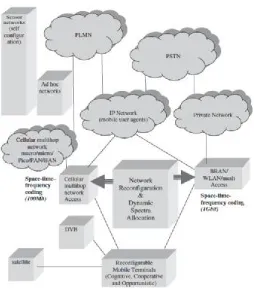
Nowadays, a multiplicity of radio access technology (RAT) standards are used in
wireless communications. As shown in Figure 1., these technologies can be roughly
categorized in four sets:
• Cellular networks that include second-generation (2G) mobile systems, such as Global System for Mobile Communications (GSM) [1], and their evolutions,
often called 2.5G systems, such as enhanced digital GSM evolution (EDGE),
General Packet Radio Access (GPRS) [2], and IS 136 in the US. These systems
are based on TDMA technology. Third generation (3G) mobile networks,
known as Universal Mobile Telecommunications Systems (UMTS) (WCDMA
and cdma2000) [3] are based on CDMA technology that provides up to 2
Mbit/s. Long-term evolution (LTE) [4-12] of these systems is expected to
evolve into 4G system providing up to 100 Mbit/s on the uplink and up to 1
Gbit/s on the downlink. The solutions will be based on a combination of
multicarrier and space-time signal formats. The network architectures include
macro, micro, and pico cellular networks and home (HAN) and personal area
network (PAN).
• Broadband radio access network (BRANs) [13] or wireless local area networks (WLANs) [14] which are expected to provide up to 1 Gbit/s in 4G. These
technologies are based on OFDMA and space-time coding.
• Digital video broadcasting (DVB) [15] and satellite communications.
109 Figure 1. Composite radio environment in cognitive, cooperative, and opportunistic
4G networks.
2.
System Architecture
In order to increase the spectral efficiency further, besides the space-time
frequency coding in the physical layer, the paradigms like cognitive [16-18],
cooperative [19-21], and opportunistic [22-24] solutions will be used.
Although 4G is open for new multiple access schemes, the CRE concept
remains attractive for increasing the service provision efficiency and the exploitation
possibilities of the available RATs. The main assumption is that the different radio
networks, GPRS, UMTS, BRAN/WLAN, DVB, and so on, can be components of a
heterogeneous wireless access infrastucture. A network provider (NP) can own
several components of the CR infrastructure (in other words, can own licenses for
deploying and operating different RATs), and can also cooperate with affiliated NPs.
110
achieving the required capacity and QoS levels, in a cost-efficient manner. Users are
directed to the most appropriate radio networks and technologies, at different service
area regions and time zones of the day, based on profile requirements and network
performance criteria. The various RATs are thus used in a complementary manner
rather than competing each other. Even nowadays a mobile handset can make a
handoff between different RATs. The deployment of CRE systems can be facilitated
by the reconfigurability concept, which is an evolution of a software-defined radio [25, 26]. The CRE requires terminals that are able to work with different RATs, and
the existence of multiple radio networks offering alternate wireless access
capabilities to service area regions. Reconfigurability supports the CRE concept by
providing essential technologies that enable terminals and network elements
dynamically (transparently and securely) to select and adapt to the set of RATs that
are most appropriate for the conditions encountered in specific service area regions
and time zones of the day. According to the reconfigurability concept, RAT selection
is not restricted to those that are pre-installed in the network element. In fact, the
required software components can be dynamically downloaded, installed, and
validated. This makes it different from the static paradigm regarding the capabilities
of terminals and network elements.
The networks provide wireless access to IP (Internet protocols)-based
applications and service continuity in the light of infrasystem mobility. Integration of
the network segments in the CR infrastructure is achieved through the management
system for the CRE (MS-CRE) components attached to each network. The
management system in each network manages a specific radio technology; however,
the platforms can cooperate. The fixed (core and backbone) network will consist of
public and private segments based on Ipv4- and Ipv6-based infrastructures. A mobile
IP (MIP) will enable the maintenance of IP-level connectivity regardless of the likely
changes in the underlying radio technologies used that will be imposed by the CRE
concept.
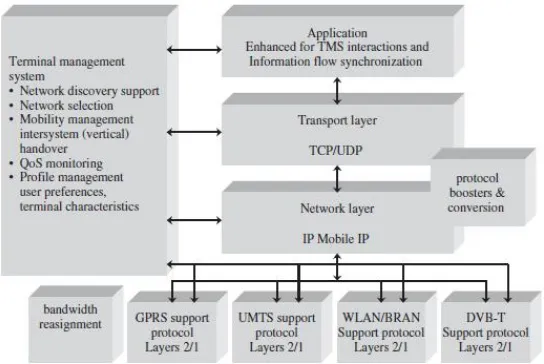
Figures 2. and 3. depict the architecture of a terminal that is capable of
operating in a CRE context. The terminals include software and hardware
components (layer 1 and 2 functionalities) for operating with different system. The
111 continuous access to IP-based applications. Different protocol busters can further
enhance the efficiency of the protocol stack. There is a need to provide the best
possible IP performace over wireless links, including legacy systems. Within the
performance implications of link characteristics (PILC) and the IETF group, the
concept of a performance-enhancing proxy (PEP) [27-30] has been chosen to refer to
a set of methods used to improve the performance of Internet protocols on network
paths where native TCP/IP performance is degraded due to characteristics of a link.
Different types of PEPs, depending on their basic functioning, are also distinguished.
Some of them try to compensate for the poor performance by modifying the
protocols themselves. In contrast, a symmetric/asymmetric boosting approach,
transparent to the upper layers, is often both more efficient and flexible.
A common framework to house a number of different protocol boosters
provides high flexibility, as it may adapt to both the characteristics of the traffic
being delivered and the particular conditions of the links. In this sense, a control
plane for easing the required information sharing (cross-layer communication and
configurability) is needed. Furthermore, another requirement comes from the
appearance of multihop communications, as PEPs have been traditionally used over
the last hop, so they should be adapted to the multihop scenario.
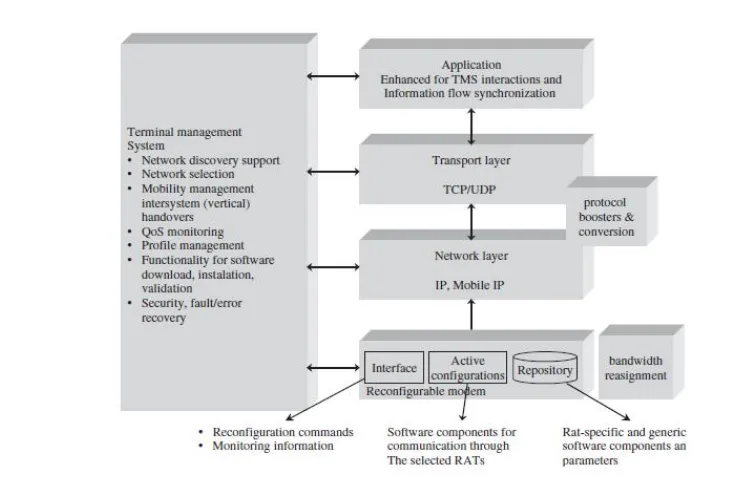
112
Figure 3. Architecture of a terminal that operates in the reconfigurability context.
Most communications networks are subject to time and regional variations in
traffic demands, which lead to variations in the degree to which the spectrum is
utilized. Therefore, a service’s radio spectrum can be underused at certain times or
geographical areas, while another service may experience a shortage at the same
time/place. Given the high economic value placed on the radio spectrum and the
importance of spectrum efficiency, it is clear that wastage of radio spectrum must be
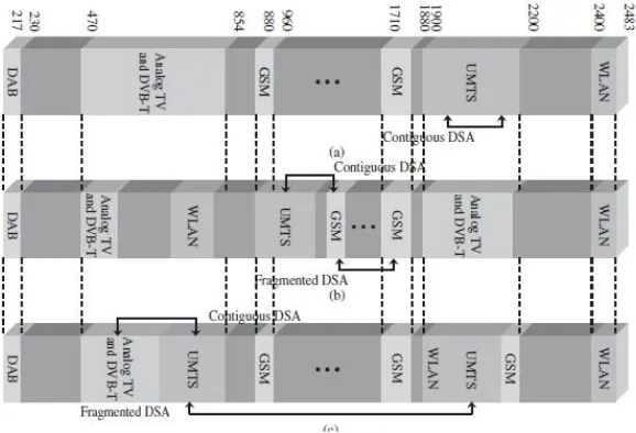
avoided. These issues provide the motivation for a scheme called dynamic spectrum
allocation (DSA), which aims to manage the spectrum utilized by a converged radio
system and share it between participating radio networks over space and time to
increase overall spectrum efficiency, as shown in Figures 4. and 5.
Composite radio systems and reconfigurability, discussed above, are potential
enablers of DSA systems. Composite radio systems allow seamless delivery of
services through the most appropriate access network, and close network cooperation
can facilitate the sharing not only services but also spectrum. Reconfigurability is
also a very important issue, since with a DSA system a radio access network could
potentially be allocated any frequency at any time in any location. It should be noted
113 information streams of the same application, which could be transported
simultaneously over different RATs.
Figure 4. Fixed spectrum allocation compared to contiguous and fragmented DSA.
Figure 5. DSA operation configurations: (a) static (current spectrum allocations); (b)
continuous DSA operations; (c) discrete DSA operations.
The terminal management system (TMS) is essential for providing
114
focus is on the determination of the networks that provide, in a cost-efficient manner,
the best QoS levels for the set of active applications. A first requirement is that the
MS-CRE should exploit the capabilities of the CR infrastructure. This can be done in
a reactive or proactive member.
Reactively, the MS-CRE reacts to new service area conditions, such as the
unexpected emergence of hot spots. Proactively, the management system can
anticipate changes in the demand pattern. Such situations can be alleviated by using
alternate components of the CR infrastructure to achieve the required capacity and
QoS levels. The second requirement is that the MS-CRE should provide resource
brokerage functionality to enable the cooperation of the networks of the CR
infrastucture. Finally, parts of the MS-CRE should be capable of directing users to
the most appropriate networks of the CR infrastucture, where they will obtain
services efficiently in terms of cost and QoS. To achieve the above requirements the
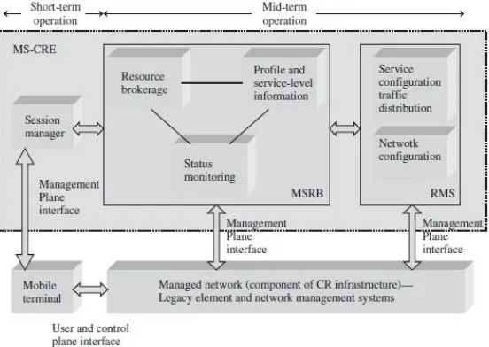
MS architecture shown in Figure 6. is required.
The architecture consists of three main logical entities:
• Monitoring, service-level information and resource brokerage (MSRB).
• Resource management strategies (RMS).
• Session managers (SMs).
115 The MSRB entity identifies the triggers (events) that should be handled by the
MS-CRE and provides corresponding auxiliary (supporting) functionality. The RMS
entity provides the necessary optimization functionality. The SM entity is in charge
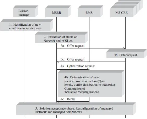
of interacting with the active subscribed user/terminals. The operations steps and
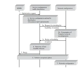
cooperation of the RMS components are shown in Figures 7. and 8., respectively.
In order to gain an insight into the scope and range of possible
reconfigurations, review the network and protocol stack architectures of the basic
CRE components as indicated in Figure 1.
116
Figure 8. Cooperation of the RMS components.
3.
Protocol Boosters Analysis
As pointed out in Figure 2., an element of the reconfiguration in 4G networks
are protocol boosters. A protocol boosters is a software or hardware module that
transparently improves protocol performance. The booster can reside anywhere in the
network or end systems, and may operate independently (one-element booster) or in
cooperation with other protocol boosters (multielement booster). Protocol boosters
provide an architectural alternative to existing protocol adaptation techniques, such
as protocol conversion.
A protocol booster is a supporting agent that by itself is not a protocol. It may
add, delete, or delay protocol messages, but never originates, terminates, or convert
that protocol. A multielement protocol booster may define new protocol messages to
exchange among themselves, but these protocols are originated and terminated by
protocol booster elements, and are not visible or meaningful external to the booster.
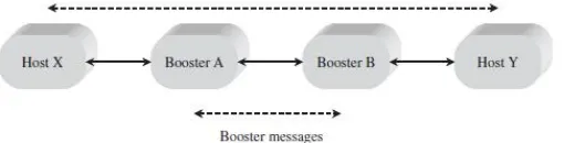
Figure 9. shows the information flow in a generic two-element booster. A protocol
booster is transparent to the protocol being boosted. Thus, the elimination of a
protocol booster will not prevent end-to-end communication, as would, for example,
117 Figure 9. Two-element booster.
Some examples of protocol busters are:
1. One-element error detection booster for UDP
UDP has an optional 16-bit checksum field in the header. If it contains the
value zero, it means that the checksum was not computed by the source.
Computing this checksum may be wasteful on a reliable LAN. On the other
hand, if errors are possible, the checksum greatly improves data integrity. A
transmitter sending data does not compute a checksum for either local or
remote destinations. For reliable local communications, this saves the
checksum computation (at the source and destination). For wide-area
communication, the single-element error detection booster computes the
checksum and puts it into the UDP header. The booster could be located either
in the source host (below the level of UDP) or in gateway machine.
2. One-element ACK compression booster for TCP
On a system with assymetric channel speeds, such as broadcast satellite, the
forward (data) channel may be considerably faster than the return (ACK)
channel. On such a system, many TCP ACKs may build up in a queue,
increasing round-trip time and thus reducing the transmission rate for a given
TCP window size. The nature of TCP’s cumulative ACKs means that any ACK
acknowledges as least as many bytes of data as any earlier ACK. Consequently,
if several ACKs are in a queue, it is necessary to keep only the ACK that has
arrived most recently. A simple ACK compression booster could ensure that
only a single ACK exists in the queue for each TCP connection. (A more
sophisticated ACK compression booster allows some duplicate ACKs to pass,
118
The booster increases the protocol performance because it reduces the ACK
latency and allows faster transmission for a given window size.
3. One-element congestion control booster for TCP
Congestion control reduces buffer overflow loss by reducing the transmission
rate at the source when the network is congested. A TCP transmitter deduces
information about network congestion by examining acknowledgments (ACKs)
sent by the TCP receiver. If the transmitter sees several ACKs with the same
sequence number, then it assumes that network congestion caused a loss of data
messages. If congestion is noted in a subnet, then a control booster could
artificially produce duplicate ACKs. The TCP receiver would think that data
messages have been lost because of congestion, and would reduce its window
size, thus reducing the amount of data it injects into the network.
4. One-element ARQ booster for TCP
TCP uses ARQ to retransmit data unacknowledged by the receiver when a
packet loss is suspected, such as after a retransmission timeout expires.
Assuming the network of Figure 9. (except that Booster B does not exist), then
an ARQ booster for TCP will:
a) cache packets from Host Y;
b) if it sees a duplicate acknowledgment arrive from Host X and it has the next
packet in the cache, then it deletes the acknowledgment and retransmits the
next packet (because a packet must have been lost between the booster and
Host X);
c) delete packets retransmitted from Host Y that have been acknowledged by
Host X.
The ARQ booster improves performance by shortening the retransmission path.
A typical application would be if Host X were on a wireless network and the
booster were on the interface between the wireless and wireline networks.
5. A forward erasure correction booster for IP or TCP
For many real time and multicast applications, forward error correction coding
is desirable. The two-element FZC booster uses a packet forward error
119 of the network adds parity packets. The FZC booster at the receiver side
removes the parity packets and regenerates missing data packets. The FZC
booster can be applied between any two points in a network (including the end
systems). If applied to an IP, then a sequence number booster adds sequence
number information to the data packets before the first FZC booster. If applied
to TCP (or any protocol with sequence number information), then the FZC
booster can be more efficient because:
a) it does not need to add sequence numbers.
b) it could add new parity information on TCP retransmission (rather than
repeating the same parities).
At the receiver side, the FZC booster could combine information from multiple
TCP retransmissions for FZC decoding.
6. Two-element jitter control booster for IP
For real time communications, we may be interested in bounding the amount of
jitter that occurs in the network. A jitter control booster can be used to reduce
jitter at the expense of increased latency. At the first booster element, the
timestamps are generated for each data message that passes. These timestamps
are transmitted to the second booster element, which delays messages and
attempts to reproduce the intermessage interval that was measured by the first
booster element.
7. Two-element selective ARQ booster for IP or TCP
For links with significant errors rate using a selective ARQ protocol (with
selective acknowledgment and selective retransmission) can significantly
improve the efficiency compared to using TCP’s ARQ (with cumulative
acknowledgment and possibly go-back-N retransmission). The two element ARQ booster uses a selective ARQ booster to supplement TCP by:
a) caching packets in the upstream booster,
b) sending negative acknowledgments when gaps are detected in the
downstream booster,
c) selectively retransmitting the packet requested in the negative
120
4.
Discussion and further development
4G wireless networks might be using a spatial notching (angle α) to suppress
completely antenna radiation towards the user, as illustrated in Figure 10. These
solutions will be referred to as ‘green wireless networks’ for obvious reasons. In
order to ensure the connectivity in the case when antenna lobe is not directed towards
the access point, a multihop communication, with the possibility of relaying, is
required. In addition, to reduce the overall transmit power a cooperative transmit
diversity and adaptive medium access control (MAC) protocol can be used.
Figure 10. 1: Three-dimensional amplitude patterns of a two-element uniform
amplitude array for d=2λ, directioned towards (a) , (b)
;
2: Three-dimensional amplitude patterns of a ten-element uniform
amplitude array for d=λ/4, directioned towards (a) , (b)
121
References
[1] M. Mouly and M. –B. Pautet, The GSM System for Mobile Communications, Palaiseau, France, 1992.
[2] R. Kalden, I. Meirick, and M. Meyer, Wireless Internet access based on GPRS,
IEEE Pers. Commun., vol.7, no.2, April 2000, pp 8-18.
[3] 3rd Generation Partnership Project (3GPP), http://www.3gpp.org.
[4] P. Mogensen, Wei Na, I. Z. Kovacs, F. Frederiksen, A. Pokhariyal, K. I.
Pedersen, T. Kolding, K. Hugl and M. Kuusela, LTE capacity compared to the
Shannon bound, in Vehicular Technology Conf., 22-25 April 2007, pp. 1234-1238.
[5] H. Holma, A. Toskala, K. Rantha-aho, and J. Pirskanen, High-speed packet
access evolution in 3GPP Release 7 [Topics in Radio Communications], IEEE Commun. Mag., vol. 45, no. 12, December 2007, pp. 29-35.
[6] A. Hoikkanen, A techno-economic analysis of 3G long-term evolution for
broadband access, in Conf. on Telecommun. Techno-Economics, 14-15 June 2007, pp. 1-7.
[7] A. Racz, A. Temesvary, N. Reider, Handover performance in 3GPP long term
evolution (LTE) systems, in Mobile and Wireless Commun. Summit, 16th IST,
1-5 July 2007, pp. 1-5.
[8] M. Valkama, L. Anttila and M. Renfors, Some radio implementation challenges
in 3G-LTE context, in Signal Processing Advances in Wireless Commun.,
IEEE 8th Workshop on SPAWC 2007, 17-20 June, pp. 1-5.
[9] J. J. Sanchez, D. Morales-Jimenez, G. Gomez and J. T. Enbrambasaguas,
Physical Layer performance of long term evolution in cellular technology, in
16th IST Mobile and Wireless Commun. Summit, 1-5 July 2007, pp. 1-5.
[10] J. Berkmann, C. Carbonelli, F. Dietrich, C. Drewes, and Wen Xu, On 3G LTE
terminal implementation – standards, algorithms, complexities, and challenges,
in International Wireless Commun. and Mobile Computing Conf. IWCMC ’08, 6-8 August 2008, pp. 970-975.
[11] C. Spiegel, J. Berkmann, Zijian Bay, T. Scholand, and C. Drewes, MIMO
122
[12] S.-E. Elayoubi, O. Ben Haddada, and B. Fourestie, Performance evaluation of
frequency planning schemes on OFDMA-based networks, IEEE Trans. Wireless Commun., vol. 7, no. 5, part1, May 2008, pp. 1623-1633.
[13] J. Khun-Jush et al., HiperLAN2: broadband wireless communications at 5 GHz, IEEE Commun. Mag., vol. 40, no. 6, June 2002, pp. 130-137.
[14] U. Varshney, The status and future of 802.11-based WLANs, IEEE Comp., vol. 36, no. 6, June 2003, pp. 102-105.
[15] Digital Video Broadcasting (DVB), http://www.dvb.org, January 2002.
[16] V. Stavroulaki, P. Demestichas, A. Katidiotis, and D. Petromanolakis,
Evolution in equipment management concepts; from reconfigurable to
cognitive wireless terminals, in 16th IST Mobile and Wireless Commun. Summit, 1-5 July 2007, pp. 1-5.
[17] R. Muraleedharan and L. A. Osadciw, Increasing QoS and security in 4G
networks using cognitive intelligence, in IEEE Globecom Workshops, 26-30 November 2007, pp. 1-6.
[18] I. F. Akyildiz, W.-Y. Lee, M. C. Vuran, and S. Mohanty, Next
generation/dynamic spectrum access/cognitive radio wireless networks: a
survey, Computer Networks J., Elsevier, vol. 50, September 2006, pp. 2127-2159.
[19] K. Doppler, A. Osseiran, M. Wodczak, and P. Rost, On the integration of
cooperative relaying the WINNER system concept, in 16th IST Mobile and
Wireless Commun. Summit, 1-5 July 2007, pp. 1-5.
[20] Qian Zhang, Qing Chen, Fan Yang, Xuemin Shen, and Zhisheng Niu,
Cooperative and oppurtunistic transmission for wireless ad hoc networks, IEEE Network, vol. 21, no. 1, January-February 2007, pp. 14-20.
[21] Carlos Leonel Flores Mayorga, Francescantonio della Rosa, Satya Ardhy
Wardana, Gianluca Simone, Marie Claire Naima Raynal, Joao Figueiras, and
Simone Frattasi, Cooperative positioning techniques for mobile localization in
4G cellular networks, in IEEE Int. Conf. on Pervasive Services, 15-20 July 2007, pp. 39-44.
[22] Yu Wu, Ji-bo Wei, Yong Xi, Byung-Seo Kim and Sung Won Kim,
123 networks, in IEEE 18th Int. Symp. on Personal, Indoor and Mobile Radio
Commun., PIMRC 2007, 3-7 September 2007, pp. 1-5.
[23] S. Mangold, Zhun Zhong, K. Challapali, and Chun-Ting Chou, Spectrum agile
radio: radio resource measurements for opportunistic spectrum usage, in IEEE Global Telecommun. Conf. 2004, GLOBECOM ’04, vol. 6, 29 November-3 December 2004, pp. 3467-3471.
[24] W. Ajib and D. Haccoun, An overview of scheduling algorithms in
MIMO-based fourth-generation wireless systems, IEEE Network, vol. 19, no. 5, September-October 2005, pp. 43-48.
[25] S. Glisic, Advanced Wireless Communications: 4G Cognitive and Cooperative Broadband Technology, 2nd edition. John Willey & Sons, Ltd: Chichester, London, 2007.
[26] J. Mitola III and G. Maguire Jr., Coginitive radio: making software radios more
personal, IEEE Pers. Commun., vol. 6, no. 4, August 1999, pp. 13-18.
[27] J. Border et al., Performance enhancing proxies intended to mitigate link-related degradations, RFC 3135, June 2001.
[28] D. C. Feldmeier et al., Protocol boosters, IEEE J. Selected Areas Commun., vol. 16, no.3, April 1998, pp. 437-444.
[29] M. Garcia et al., An experimental study of snoop TCP performance over the IEEE 802.11b WLAN, in 5th Int. Symp. on Wireless Personal Multimedia Commun., vol. III, Honolulu, HA, October 2002, pp. 1068-1072.
[30] L. Munoz et al., Optimizing Internet flows over IEEE 802.11b wireless local area networks: a performance enchancing proxy based on forward error