1234567890
IAES International Conference on Electrical Engineering, Computer Science and Informatics IOP Publishing
IOP Conf. Series: Materials Science and Engineering 1234567890190 (2017) 012006 doi:10.1088/1757-899X/190/1/012006
IAES International Conference on Electrical Engineering, Computer Science and Informatics IOP Publishing
IOP Conf. Series: Materials Science and Engineering 190 (2017) 012006 doi:10.1088/1757-899X/190/1/012006
Comparison of PID and Fuzzy Controller for Position Control
of AR.Drone
A Prayitno1, V Indrawati2 and I I Trusulaw3
1,2,3 Electrical Engineering Department, University of Surabaya (UBAYA)
Raya Kalirungkut, Surabaya 60293, East Java, Indonesia, Tel.+62-31-2981157
1 prayitno_agung@staff.ubaya.ac.id
Abstract. This paper describes the implementation of the PID Controller to control the position of the AR.Drone in the x-y-z. This position control scheme uses three PID controllers to maintain the position of x, y and z using the signal control pitch, roll and vertical rate. PID Controller implemented on AR.Drone 2.0 and then tested in an indoor space. The performance of the controller will be compared with Fuzzy Logic Controller schemes that have been implemented previously. The results show that the PID Controller generate a response with rise time less than 3 seconds at the x and y position with around 25% overshoot. The result for z position give better result without overshoot. The comparison between fuzzy logic and PID Controller indicates that the results of the PID controller is better although there is overshoot.
1. Introduction
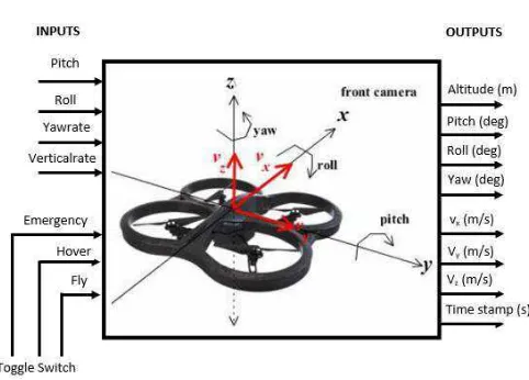
Currently, the AR.Drone is widely used by researchers for its research platform. AR.Drone was chosen because it is relatively inexpensive but has onboard controller and internal software. AR.Drone body constructs from frame which made of carbon pipe with 4 brushless motors complete with propellers and the main body is made of plastics fiber in which there are onboard electronics and Lithium-Polymer (Li-Po) battery. User can access controller via Wi-Fi communication. The onboard controller consists of motherboard and navigation board. On the motherboard, there are the processor, front camera, bottom camera, and Wi-Fi chips. On the navigation board there is a microcontroller board that use as an interface to the sensors. AR.Drone equipped with accelerometer, gyroscope and ultrasonic altimeter [1].
2 1234567890
IAES International Conference on Electrical Engineering, Computer Science and Informatics IOP Publishing
IOP Conf. Series: Materials Science and Engineering 1234567890190 (2017) 012006 doi:10.1088/1757-899X/190/1/012006
IAES International Conference on Electrical Engineering, Computer Science and Informatics IOP Publishing
IOP Conf. Series: Materials Science and Engineering 190 (2017) 012006 doi:10.1088/1757-899X/190/1/012006
Figure 1.AR.Drone Inputs – Outputs.
Many studies have described a variety of development and application using the AR.Drone. Michael [2] created LabVIEW Toolkits consisting of Main VI, Video VI, NavData VI, and Additional Supporting VI to control the AR.Drone. This software has the ability to transmit control commands and keep the communication channel running, read UDP packets that contain video frame sent from
the AR.Drone, sends UDP packets that contain sensor’s navigation data outport to the IP address of
the computer and estimate x, y, z position of the navigation data. Krajnik [3] formulated four AR.Drone structure models which has input output relations: setpoint pitch - actual pitch - forward speed; setpoint roll - actual roll - sideward speed, setpoint yaw rate - actual yaw rate - yaw, and setpoint vertical rate –actual rate vertical - altitude. Agung [4] calculated model of roll, pitch, yaw rate and critical rate with a step response test on the AR.Drone 1.0. Sarah [5] identified the model parameters of the internal and dynamic model of AR.Drone using second order system approach. Some control scheme are designed and implemented the the model obtained. The control schemes are waypoint navigation controller, leader-follower behavior, trajectory-following behavior. Agung [6] designed a fuzzy scheme trajectory tracking control for applications in x-y coordinates. This fuzzy scheme has two inputs that distance, angle and has two outputs, namely pitch, yawrate. Fuzzy control scheme tested on straight and curved trajectory. Veronica [7] implemented fuzzy logic control for waypoint navigation applications. This fuzzy scheme uses three fuzzy logic to control pitch, roll and vertical rate respectively with each input in the form of desired position and the actual position. Three scenarios were designed and implemented for the waypoint problem. The test results indicate that the fuzzy scheme can be used for waypoint applications. Veronica [8] implemented position control of ar.drone by using two fuzzy control. The first fuzzy used to control pitch and yawrate simultaneously with the input of distance and angle, while the fuzzy second is used to control the vertical rate using the input of desired and actual position z.
This paper reports the development of the PID controller scheme to control the position of the AR.Drone in the x-y-z. The result then compares with fuzzy control schemes that have been implemented in [8].
2. PID Controller Design
1234567890
IAES International Conference on Electrical Engineering, Computer Science and Informatics IOP Publishing
IOP Conf. Series: Materials Science and Engineering 1234567890190 (2017) 012006 doi:10.1088/1757-899X/190/1/012006
IAES International Conference on Electrical Engineering, Computer Science and Informatics IOP Publishing
IOP Conf. Series: Materials Science and Engineering 190 (2017) 012006 doi:10.1088/1757-899X/190/1/012006
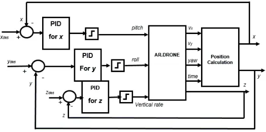
Figure 2.Block diagram of control system.
· Understanding the dynamics of the system AR.Drone. To understand the dynamics of the system, do the step response test on the system pitch, roll and vertical rate of AR.Drone by giving a value ranging from -1 up to 1. Navigation data such as actual pitch, forward speed, x, actual roll, sideward speed, y, vertical rate, and z are recorded and analyzed.
· From the data obtained, considering the limitations of indoor space there should be restrictions on the control signals. Pitch in the range of -0.115 to 0.115, roll in range of -0.125 to 0.125
· Formulate each subsystem PID controller, figure 3, into a computer program. For easy programming and implementation, the PID equation converted as follow.
= ( ) + !∫ ( ) + #$%(&)$& (1)
= ∗ **,* + (!∗ -. /*01 ∗ 2 ) + (#∗$%33$& ) (2)
where:
: Proportional Constant
! : Integral Constant
# : Derivative Constant
**,* = 24-*2 6,-. − 08 901 6,-. -. /*01 = -. /*01:3%;<>?@+ **,*
2** = **,* − **,*:3%;<>?@
2 : execution time
4 1234567890
IAES International Conference on Electrical Engineering, Computer Science and Informatics IOP Publishing
IOP Conf. Series: Materials Science and Engineering 1234567890190 (2017) 012006 doi:10.1088/1757-899X/190/1/012006
IAES International Conference on Electrical Engineering, Computer Science and Informatics IOP Publishing
IOP Conf. Series: Materials Science and Engineering 190 (2017) 012006 doi:10.1088/1757-899X/190/1/012006
· Realize the system into computer program, block diagram and front panel.
· By trial and error, tune the PID parameter until obtain the best response. The obtained parameter is tabulated in table 1.
Table 1.PID Parameters.
Parameters Values
PID for pitch PID for roll PID for vertical rate
Kp 1.6 1.6 1
Ki 0.005 0.005 1
Kd 0.5 0.5 2
3. Results and Analysis
PID controller is implemented on the AR.Drone 2.0 and flown at indoor laboratory. The testing process is conducted as follows:
· From the front panel, specify the setpoint position x, y and z, which are trying to reach by the AR.Drone.
· With the push button on the front panel, AR.Drone fly hover as high as 1 m. The hover position is considered as the initial coordinat (0,0,0).
· Then switch OFF hover in front panel, AR.Drone will fly autonomous with PID Controller designed to the setpoint. During flew the flight data is recorded.
· When it reaches the intended position, indicated hover fly, AR.Drone is landed.
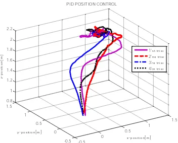
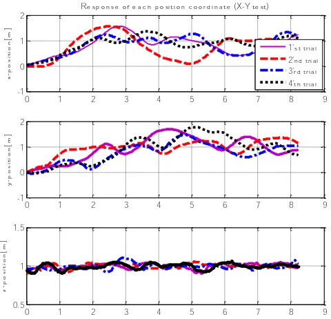
The results of four time testing at the set point (1,1,1) are shown in figure 4 and figure 5. Figure 4 are 3-D representation, while figure 5 is 2-D representation of the AR.Drone response.
Figure 4.Experiment result of PID Position
Control in 3-D.
Figure 5. Experimental results of PID Position
Control in 2-D.
From the test results, figure 5, it appears that the AR.Drone can reach the desired position with a rise time of about 2 seconds, has about 25% overshoot and settling time of about 4 seconds. From 3-D graphics, figue 4, it appears that the AR.Drone experienced oscillations around the setpoint.
1234567890
IAES International Conference on Electrical Engineering, Computer Science and Informatics IOP Publishing
IOP Conf. Series: Materials Science and Engineering 1234567890190 (2017) 012006 doi:10.1088/1757-899X/190/1/012006
IAES International Conference on Electrical Engineering, Computer Science and Informatics IOP Publishing
IOP Conf. Series: Materials Science and Engineering 190 (2017) 012006 doi:10.1088/1757-899X/190/1/012006
Tests were also done on the set point (1,1,0) to see the response AR.Drone in flight the x-y plane.The results of four time testing are shown in figure 8.
Figure 6.Experimental results of PID Position Control in 2-D.
4. Comparison with Fuzzy Control Scheme
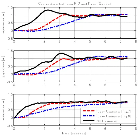
Results PID position control is compared with the Fuzzy position control implemented by Veronica [8],
where the fuzzy scheme is shown in figure 7 and figure 8:
Figure 7. First fuzzy scheme implemented
on [8].
Figure 8. Second fuzzy scheme implemented on
[8].
Similar to the PID Controller scheme, scheme in figure 7, uses three pieces of FLC controller to control pitch, roll and vertical rate simultaneously. Each fuzzy input is the desired position and the actual position. While scheme in figure 8 uses only two pieces of fuzzy control for pitch and yawrate simultaneously and fuzzy logic for the vertical rate.
The results of the comparison PID response with two fuzzy schemes that has been done is shown in figure 9. It is noticeable that the PID controller generates a better response both in the x, y and z, but has a slightly higher overshoot
0 1 2 3 4 5 6 7 8 9
Response of each position coordinate (X-Y test)
6 1234567890
IAES International Conference on Electrical Engineering, Computer Science and Informatics IOP Publishing
IOP Conf. Series: Materials Science and Engineering 1234567890190 (2017) 012006 doi:10.1088/1757-899X/190/1/012006
IAES International Conference on Electrical Engineering, Computer Science and Informatics IOP Publishing
IOP Conf. Series: Materials Science and Engineering 190 (2017) 012006 doi:10.1088/1757-899X/190/1/012006
Figure 9.Comparation of two control schemes.
5. Conclusion
To control position of x, y, zof the AR.Drone can be realized with three PID controller to manipulate
the pitch, roll and vertical rate. The implementation results show that PID controlled system gives response with a rise time of about 2 seconds, 25% overshoot and settling time of about 4 seconds. The results of the comparison between PID controlled system and fuzzy controlled system, the PID controlled system gives better result in this experiment.
References
[1] Pierre-Jean B, Francois C, David V and Nicolas P 2011 The navigation and control technology inside the AR drone micro UAV 18th IFAC World Congress Milano Italy
[2] Michael M 2012 The AR drone LabVIEW toolkit: A software framework for the control of low cost quadrotor aerial robots (Master of Science Thesis - TUFTS University)
[3] Krajnik T, Vonasek V, Fiser D and Faigl J 2011 AR-drone as a platform for robotic research and education. Research and Eductation in Robotics EUROBOT Heidelberg
[4] Agung P and Veronica I 2014 Model AR.drone dengan indoor dan outdoor Hull Proceeding CITEE Yogyakarta Indonesia.
[5] Sarah Y Tang 2013 Vision-based control for autonomous quadrotor (Final Report :Undergraduated Senior Thesis. Department of Mechanical and Aerospace Engineering. Princeton University)
[6] Agung P, Veronica I and Gabriel U 2014 Trajectory tracking of AR.drone quadrotor using fuzzy logic controller J. Telkomnika 12(4) 819
[7] Veronica I, Agung P and Thomas A Kurniawan 2015 Waypoint navigation of AR.drone quadrotor using fuzzy logic controller J. Telkomnika 13(3) 930
[8] Veronica I, Agung P and Gabriel U 2015 Comparison of two fuzzy logic controller schemes for position control of AR.drone Proceeding of 7th International Conference on Information
Technology and Electrical Engineering (ICITEE) Chiangmai Thailand
0 1 2 3 4 5 6 7 8
Comparison between PID and Fuzzy Control