Impact of seismic design on tunnels in rock – Case histories
Carlos A. Jaramillo
COWI North America, 1300 Clay Street, 7th Floor, Oakland, CA 94612, USA
Received 24 January 2017; received in revised form 2 March 2017; accepted 8 March 2017 Available online 10 April 2017
Abstract
The tunnel industry has considered that tunnels, especially tunnels in rock, are naturally resistant to earthquake action, including faulting, shaking, deflection and ground failure. As the number of case histories of tunnels subject to earthquake action has increased, the industry has started to recognize that, although tunnels in rock have good resistance against earthquakes generating peak ground accelerations (PGA) lower than 0.5 g, it is important to include the dynamic forces and displacements generated by seismic ground motions in the design process to obtain a more reliable design. These additional earthquake forces impact the final design, potentially requiring changes to the ground support and additional reinforcement of the concrete lining, as illustrated by case histories presented in this paper.
Ó2017 Tongji University and Tongji University Press. Production and hosting by Elsevier B.V. on behalf of Owner. This is an open access article
under the CC BY-NC-ND license (http://creativecommons.org/licenses/by-nc-nd/4.0/).
Keywords: Tunnel; Tunnels; Seismic design; Earthquake impact; Tunnel lining; Ground support
Introduction
The tunnel industry considered that tunnels were natu-rally resistant to earthquake action for many years, as they did not experience the same high levels of shaking as sur-face structures. This perception was supported by the rela-tive good historic performance of tunnels and underground structures, especially of tunnels in rock, during large earth-quakes.Dowding and Rozen (1978) presented one of the first compilations of damage to rock tunnels due to earth-quake shaking. They collected information on 71 tunnels and compared their behavior with estimated peak ground accelerations (PGAs) and peak ground velocities (PGVs). Their conclusions can be summarized as follow:
Collapse of tunnels from shaking occurs only under extreme conditions.
No damage occurred when PGAs were lower than 0.19 g and/or PGVs were lower than 0.2 m/s.
Minor to moderate damage occurred when PGAs were up to 0.5 g and PGVs up to 0.9 m/s.
Moderate to heavy damage occurred when PGAs were larger than 0.5 g.
Tunnel collapse only occurred associated with move-ment of an intersected fault.
Tunnels are much safer than above ground structures for any given event.
Several additional reviews of tunnel performance during earthquakes have been published since Dowding and Rozen (1978), including Powers, Rosidi, and Kaneshiro (1998), and being particularly important the reviews per-formed after large earthquakes in Taiwan (Wang et al., 2001), Japan (Kosugi, Hatsuku, & Shimonishi, 2011; Yashiro, Kojima, & Shimizu, 2007), and China (Lin & Chai, 2008; Li, 2011). These additional data points have confirmed that tunnels can actually behave quite well dur-ing earthquakes, but that their response is more complex than initially expected.
http://dx.doi.org/10.1016/j.undsp.2017.03.004
2467-9674/Ó2017 Tongji University and Tongji University Press. Production and hosting by Elsevier B.V. on behalf of Owner. This is an open access article under the CC BY-NC-ND license (http://creativecommons.org/licenses/by-nc-nd/4.0/).
E-mail address:[email protected]
Peer review under responsibility of Tongji University and Tongji University Press.
www.elsevier.com/locate/undsp
ScienceDirect
Following a parallel path, several researchers were developing analytical and numerical approaches to evalu-ate the impact of earthquakes on tunnels and evaluevalu-ate their performance, being some of the better knownSt. John and Zahrah (1987), Wang (1993), Penzien (2000), Hashash, Hook, Schmidt, and Yao (2001)and Hashash, Park, and Yao (2005), which was accredited by the International Tunneling Association (ITA). More detailed ground-structure approaches are also being considered and imple-mented as indicated among others by Corigliano, Scandella, Lai, and Paolucci (2011), Gasparini, Quaglio, and Floria (2012)andYu, Yuam, and Bobet (2013). Cur-rently most tunnel designers prepare initial ground support and final lining designs following static methods, advanc-ing to the free field procedure as per Hashash et al. (2001), and moving to a full dynamic ground-structure interaction model when the seismic hazard is high.
Impact of earthquakes on tunnels
The impact of earthquakes on tunnels is usually grouped into ground failure and ground shaking.
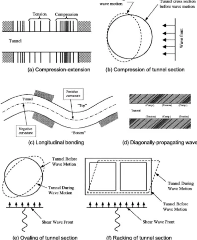
Ground failure includes liquefaction, slope instability at portals and fault displacements. For tunnels in rock lique-faction is not an issue, but slope instability and fault dis-placement can have impacts on the tunnels. Both occur at discrete locations and will not be the focus of this paper. Ground shaking refers to the variable ground deforma-tion produced by the seismic waves traveling through the earth crust. Shaking results on the type of deformation on the tunnel shown inFig. 1.
Case histories showing the impact of shaking are the focus of the paper.
Ground motions
As we mentioned above, tunnel response to earthquakes is very complex, and there are many unknowns surround-ing the data. One of the most important is related to the ground motions actually affecting the tunnel. Particularly for tunnels in rock, many of the case histories are for deep tunnels in mountainous areas. Most studies about ground motions due to earthquakes are based on data from instru-ments located in urban centers (relatively low topography areas) and collected at shallow depths, so their applicability to the case history data set of deep tunnels under high topography is unknown.
Fault displacements
The data set collected regarding behavior of tunnels dur-ing earthquakes indicate that fault displacement results in many of the major damage cases. There are several designs implemented that supposedly will resist fault displacement but none has been actually tested (Kieffer, Caulfield, & Cain, 2001; Russo, Germani, & Amberg, 2002).
Seismic design of tunnels
The design of a tunnel usually consist of the design of the ground support and the design of the final lining. The impact of earthquake action is only evaluated after a static design is available. The following sections briefly discuss the steps for static design.
Ground support
Ground support refers to the measures implemented dur-ing excavation of the tunnel to maintain its stability and the safety of the personnel working in the tunnel. The ground support has been also called temporary support, although it remained in placed through the life of the tunnel, or initial support, although in many cases no additional support was provided. Ground support measures have consisted of tim-ber columns and beams, steel sets, shotcrete and rock bolts, and pre-cast concrete segments.
The design of the ground support for tunnels in rock has been a mostly empirical process based on precedent (Barton, Lien, & Lunde, 1974; Bieniawski, 1974, 1989; Grimstad & Barton, 1993), and only becoming better sup-ported by theory with the advent of powerful computa-tional means and the efforts to develop the sequential excavation method (SEM or New Austrian Tunneling Method – NATM, ITA – Austria, 2012).
However one thing all these methods have in common is that they do not consider dynamic forces due to earthquake effects, and only recent there have been some efforts trying to understand the effect of earthquakes on the ground support (Tshering, 2011). It is also important to note that the most recent methods (SEM-NATM) try to optimize the design of the ground support so only enough support to maintain the static equilibrium as monitored by instrumentation mea-surements, is installed. This optimization reduces any excess capacity available to resist dynamic earthquake forces.
Final lining
Final lining correspond to the measures constructed within the excavated tunnel before placing it in operation. Final linings could be cast in place concrete, steel liners, concrete pipe, shotcrete, precast concrete segments, or nothing, leaving the tunnel ground support exposed.
The design of the final lining is based on a variety of design criteria not completely uniform across the industry. The final lining may be designed to resist the ground water and full ground loads under the assumption that the ground support will fail in the future, or just a nominal portion of either one. Seismic loads have been included only recently, and mostly in areas of known seismicity.
Case histories
Several case histories are presented and discussed to illustrate how tunnels designed following standard
procedures have behaved during actual earthquakes, and the impact of including the earthquake loads as part of the design of the tunnels.
Conventional excavation
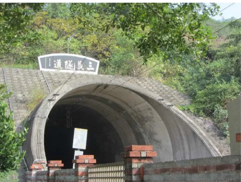
Sanyi Railway Tunnel – Chi-Chi earthquake 1999, Taiwan (Lu & Hwang, 2008)
The approximately 7 km long Sanyi tunnel was con-structed following the SEM-NATM principles. The 6 m ID tunnel was excavated parallel to a series of ridges at
depths of 20 m to 150 m and through sandstones and shales. One year after being in operation, it was subject to the Magnitude 7.3 Chi-Chi earthquake. The northern portal of the tunnel was about 5 km away from the closest seismographic station, which recorded a PGA of 0.14 g. Inspection after the earthquake indicated substantial dam-age of the concrete lining, which was attributed to excessive ground loads due to the earthquake and use of unrein-forced cast in place concrete. Both of these causes are clo-sely related to the use of SEM-NATM during excavation as follows:
The principle of SEM-NATM is to minimize the use of ground support and maximize the contribution of the ground arch. This results in substantial reduction of the weight (and cost) of ground support placed, and its over-loading due to additional stresses due to earthquake, par-ticularly in zones of poor ground conditions (seeFig. 2).
SEM-NATM assumes that the ground support and its interaction with the ground will carry any ground load dur-ing the life of the project, and the final lindur-ing will only need to carry a fraction of the groundwater load. These criteria many times result in final linings constructed of plain con-crete, strong to carry normal loads, but fragile and lacking ductility to respond to the shear loading due to earthquake motions.
Bolu Road Tunnel – Kocaeli (Izmit) earthquake 1999, Turkey and Duzce earthquake 1999 (Amberg & Russo, 2001; Giannakou et al., 2005; Russo et al., 2002; Kontoe, Zdravkovic, Potts, & Menkiti, 2008)
The 3.3 km long twin bore Bolu tunnel was constructed following SEM-NATM principles. The 14 m wide by 8.6 m height tunnels were excavated under the Bolu Mountain under up to 250 m of cover. The geology was composed of alternating crystalline and metasedimentary rock with some sections very difficult to excavate and support. The tunnel was still under construction when the Magnitude 7.4 Kocaeli event with an epicenter 150 km away occurred and generated PGAs of 0.25–0.35 g without damaging the tunnel. Three months later, the Magnitude 7.2 Duzce earthquake occurred. The west portal of the tunnel was only 20 km away from the epicenter of the Duzce event which resulted in PGA of 0.81 g. The tunnel, still under construction at the time, suffered major damage and collapse of areas that had been completed months to years before and had been stable according to the SEM-NATM monitoring.
The failure of the Bolu tunnel is another example that the ground support sized according to SEM-NATM
methods is well optimized for static conditions but does not provide sufficient capacity to resist the increased loads due to earthquake conditions (seeFig. 3).
Drumanard Tunnels Tender Design – New Madrid Fault Zone
The Drumanard Tunnels consist of approximately 595 m of twin highway tunnels excavated under the Drumanard Estate. The tunnels are horseshoe in shape, and designed to carry 2 lanes of unidirectional traffic with wide berms, which could be expanded to three lanes with narrow berms in the future. The tunnels have two side-walks in each of the tunnels, and three cross passages between the two tunnels to comply with regulatory requirements.
The tunnel excavation width and height are approxi-mately 16 m and 10.6 m respectively separated by 6 m pillar.
The tunnels were excavated through three main near horizontal rock formations, the Louisville (Upper) Lime-stone, Waldron Shale, and Laurel Dolomite in descending order of elevation. The Waldron Shale thickness in the pro-ject area is between 3.2 m and 5 m, sandwiching between the Louisville Limestone layer above and the underlying Laurel Dolomite below. The limestone and dolomite have been generally classified as fair to good quality rocks, and the shale as very poor to extremely poor quality rock based on the Q rating system (Barton et al., 1974; Grimstad & Barton, 1993), and similarly on the RMR rat-ing system (Bieniawski, 1974, 1989). The Waldron Shale has been described as the weakest rock on site, easily crum-ble and disintegrate when left to dry (i.e. low slake durabil-ity), and to soften or swell when exposed to free water (i.e. high swelling potential). The major rock discontinuities in all the rock formations on site consisted of near-horizontal bedding partings and sub-vertical joints.
The groundwater conditions varied greatly across the project site, and fluctuated with precipitation.
Fig. 2. Sanyi tunnel (SSR200 2013).
Fig. 3. Bolu tunnel portal (Lubunya, 2014).
The depth to tunnel crown is as high as 20 m and as low as 6 m. The minimum rock cover above the tunnel is shown to be as little as 5 m near the northern end of the alignment. Tunnel support was designed based on three different tunnel reaches with variable lengths of ground conditions (poor to fair ground, fair ground, and fair to good ground) requiring corresponding ground support.
The predominant failure mode during the tunnel exca-vation was anticipated to be rock slabbing or slab fallout caused by the tendency for rocks to break back to the sub-horizontal bedding and discontinuities.
The SEM-NATM design approach was based on pro-viding an optimum and cost effective, and safe design.
Tunnel cross sections– The design tunnel cross sections were derived to achieve the minimum excavations, based on the contract vehicle clearance requirements, ground support and final lining, construction tolerances, and spa-tial requirements for the tunnel system components.
Initial ground support types – Two basic initial ground support types were developed:
Type 1 ground support – This type of ground support mainly relies on pattern rock bolting to form a rein-forced rock arch above the tunnel crown (5 m long at 1.75 m every 2 m). The relatively thin shotcrete layer (75 mm) functions as lagging between the rock bolts and prevents small block fallouts.
Type 2 ground support– In the type of ground requiring this support, rock bolts support (5 m long at 1.75 m both directions) alone is not adequate to form an
adequate reinforced rock arch above the crown, and has to be supplemented by an internal arch consisting of steel fiber reinforced shotcrete (200 mm).
Excavation sequence – The tunnel was designed to be constructed using SEM-NATM and the selected excava-tion sequence consisted of a top heading and bench, with the top heading to be excavated using two side drifts.
Initial support analyses –The initial ground support scheme and sequence were validated using the FLAC (ITASCA, 2008) and UDEC (ITASCA, 2010) computer programs.
Final lining design– The tunnel lining was designed to withstand vertical rock load, external hydrostatic pressure, grouting pressure, swell pressure (in shale), and any unbal-anced loading due to the presence of karst, using the appropriate load combinations.
The primary load bearing mechanism in the tunnel crown and sidewalls is by the thrust force acting on the liner, which also provides the liner bending moment capac-ity to resist any unbalanced loading. Analyses showed that a 600 mm thick unreinforced concrete liner could be used for the tunnel crown and side walls.
the design criteria. However, the owner considered that a plain concrete lining would not provide the required public safety so steel reinforcement was added to provide ductility and prevent pieces of concrete to fall after the concrete became fractured. The impact of adding two layers of 20 mm rebar at 200 mm both directions to the concrete lin-ing increased the cost of the project and the development schedule.
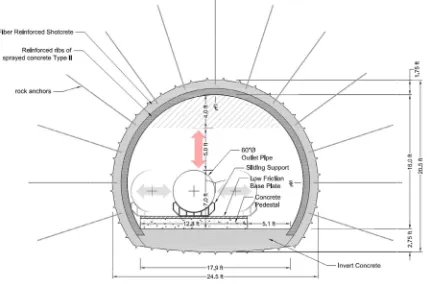
Dam Outlet – Magnitude 6.5 at 0.1 km, Magnitude 7.5 at 2 km
The project (client requested maintaining name private) includes the seismic rehabilitation of an existing dam con-structed in the 1950s so it is capable of resisting the earth-quake generated by a fault that crosses its foundation, and another fault at 2 km. Part of the rehabilitation includes reconstruction of a bottom outlet as a tunnel (Fig. 4). The new outlet tunnel will be approximately 425 m long and approximately 6.25 m high and 7.6 m wide. The tunnel ground support will also be the final lining. The ground support measures were estimated based on the Q index biased towards the poorer quality rock to account for the expected useful life and the potential earthquake loads. (Barton et al., 1974; Grimstad & Barton, 1993). The RMR method (Bieniawski, 1974, 1989) was used to con-firm the classification. The ground was classified as extre-mely poor to poor, and the ground support selected consisted of 225–300 mm of fiber reinforced shotcrete, 3 m long rock dowels at 1–1.25 m on center, and 300– 500 mm steel bar reinforced shotcrete ribs at 1.2–3.5 m. Additional ground support tools such as concrete invert,
struts, spiles, exploratory holes, pre-grouting and excava-tion staging will be available to the contractor to facilitate the excavation.
Most of the tunnel will be excavated through Franciscan Me´lange matrix containing various block percentages. The matrix of Franciscan Me´lange varies from a weak rock to soil and may consist of shale, Serpentinite or unidentified clay matrix that is pervasively sheared and intensely frac-tured, friable to moderately strong, and moderately to completely weathered. The blocks consist of Graywacke, Serpentinite, Greenstone, Chert, and Shale of various sizes but mostly limited in size to 5 m. The poorer rock condi-tions consist of extremely weak to weak, and highly to completely weathered matrix with low block percentage or Santa Clara Formation a weakly cemented and weath-ered sandstone.
As the ground support is expected to act as final lining and perform for 100 years, earthquake effects were consid-ered in great detail. Two methods were used in the analysis:
Closed-Form Solutions and Numerical Solution.
Seismic loading used to evaluate the ground support was determined by studies done for the particular site.
Closed form solution
Closed-form solutions were used to evaluate the wave propagation effects (Hashash et al., 2001). Closed-form solutions assume seismic waves propagating with constant amplitude:
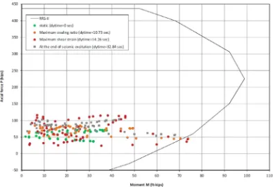
Fig. 5. Ground support capacity and earthquake demand.
1. Longitudinal strains including axial and curvature (bending) strains and corresponding induced forces and moments.
2. Ovaling strains and corresponding induced forces and moments.
The wave propagation effects were first evaluated for ‘‘free-field” condition. The procedures proposed in Hashash et al. (2001) were then followed to adjust the free-field strains for the ground-ground support interaction.
Numerical solution
A two-dimensional, plane-strain dynamic analysis was performed using the software FLAC6 (ITASCA, 2008) to evaluate the response of the ground support to the seismic loading induced by the MCE event. The objectives of the analysis were to:
1. Evaluate the free field shear strains and compare them with free-field shear strains estimated from analytical methods.
2. Determine the ovaling deformations of the tunnel including the ovaling strains.
3. Estimate the forces induced in the tunnel lining and rock anchors to ensure the lining will withstand the MCE event.
Forces and stresses in the hoop direction were computed by the FLAC analysis. Fig. 5 shows the capacity of the ground support as illustrated by its interaction diagram,
and the demands placed by the dynamic earthquake loads, as estimated from the stresses calculated by FLAC.
Comparison of results
The results of the FLAC analysis were compared with the closed-form solution results. The two solutions are based on different assumptions and use different method-ologies. Both methods confirm that the proposed ground support is adequate to resist dynamic loading. It should be noted that the ground support selected for this applica-tion is much more robust than the corresponding support estimated using traditional empirical or SEM-NATM approaches.
TBM excavation
Transportation tunnel – Regional earthquake
The project (client requested maintaining private the name of the project) includes twin two-lane TBM driven tunnels. The 12 m ID and 4.6 km long tunnels run approx-imately parallel to each other with a minimum outside clearance between the tunnels of 5 m at the tunnel portals increasing to 10 m along the majority of the tunnel length. The tunnels were excavated through phylite, quartzite and metagraywacke with a maximum ground cover of 80 m and groundwater varying from 5 to 40 m above crown.
discontinuities. The predominant failure mode during the tunnel excavation was anticipated to be rock wedges formed by the discontinuities.
The design approach consisted on providing precast concrete segments placed immediately behind a double shielded TBM and grout the annulus at the tail of the shield.
Tunnel cross sections – The design tunnel diameter was derived to achieve the minimum excavations, based on the required segment thickness, the contract vehicle clear-ance requirements, construction tolerclear-ances, and spatial requirements for the tunnel system components.
Initial ground support types– The precast concrete seg-ments were used as initial ground support, and as they were provided with gaskets, they were also designed as final lin-ing. The segments were designed to withstand a series of loads corresponding to the tunnel life cycle. Loads consid-ered were:
Rock load Water load
Fabrication and handling TBM loading
Fire loading and its impact Grouting
Depth of carbonation
These loads considered within specific load cases were the input to a beam on springs model. Several critical cases were confirmed using a 3-D finite element model of the shell formed by the segments. The resulting segments were 305 mm thick and reinforced with steel fiber.
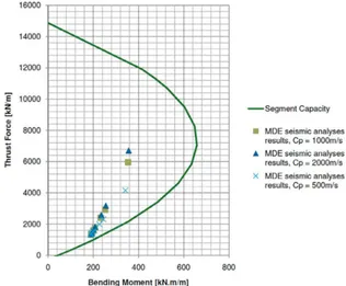
The project is located in a low seismicity zone and earth-quake effects were not initially considered, but review by the project owner’s independent verifier insisted in the con-sideration of earthquake effects. The earthquake effect was considered using the procedure presented inFHWA (2009), which is a version ofWang (1993). This procedure calcu-lates the flexibility and compressibility ratio of the struc-tures and based on these values estimates the additional thrust and bending affecting the lining. The results were then compared with the capacity of the designed segments and found to be acceptable. No changes to the design resulted from the consideration of seismic effects. Fig. 6 shows the capacity of the precast segmental lining as illus-trated by its interaction diagram, and the demands placed by the earthquake loads, as estimated using the approxi-mateFHWA, 2009method.
Conclusions
This brief review of literature and review of specific case histories the author has been involved in indicate that tun-nels in rock generally are capable of withstanding moderate earthquake events without the need to modify their designs. However, to increase the reliability of the tunnel structure and to accommodate larger events at closer
distances, it is necessary to consider the effect of the dynamic loads generated by earthquakes.
Future research on the impact of earthquakes on the ground support is necessary to obtain more reliable tunnel designs. Many tunnels are left unlined so in case of earth-quake there is no second line of defense (final lining), and the current general objective of the ground support design is efficiency, both minimizing the materials needed and the time required to install them. It is clear from the case his-tories presented that the ground support is adequate to maintain the tunnel opening stable in static conditions, but larger seismic events (PGA > 0.2 g) can cause failures of the ground support.
Additional research on the role of groundwater on the behavior of tunnels during seismic events is also necessary. Based on the author’s experience, the designer of tunnels in rock should consider these general issues:
Selection of initial ground support using empirical methods.
Confirmation of the ground support and final lining based on SEM-NATM principles.
Dimensioning of final lining.
Evaluation of earthquake impact using free field proce-dures as per Hashash et al., 2001.
Evaluation of behavior using full dynamic ground-structure interaction in locations of higher earthquake hazard.
Specific review of areas where the tunnel changes cross-section or intersects other structures.
Conflict of interest
No conflict of interest.
References
Amberg, W., Russo, M. (2001). Seismic design of underground structures the Bolu tunnel. AITES-ITA world tunneling congress.
Barton, N., Lien, R., & Lunde, J. (1974). Engineering classification of rock masses for the design of tunnel support. Rock Mechanics, 6(4), 189–236, New York, New York: Springer-Verlag.
Bieniawski, Z. T. (1974). Geomechanics classification of rock masses and its application in tunneling. Proc. Third Int. Congress on Rock Mechanics, ISRM, Denver, 27–32.
Bieniawski, Z. T. (1989).Engineering rock mass classifications. New York: John Wiley & Sons (pp. 251).
Corigliano, M., Scandella, L., Lai, C. G., & Paolucci, R. (2011). Seismic analysis of deep tunnels in near fault conditions: a case study in Southern Italy.Bull. Earthquake Eng., Springer
Dowding, C. H., & Rozen, A. (1978). Damage to rock tunnels for earthquake shaking.Journal of the Geotechnical Engineering Division, American Society of Civil Engineers, 104, GT2.
Federal Highway Administration (FHWA) (2009). Technical manual for design and construction of road tunnels.
Gasparini, G. M., Quaglio, G., Floria, V. (2012). Simplified numerical method for tunnel design under seismic condition: some examples about Istanbul metro design, geotechnical aspects of underground construction in soft ground, Viggiliani.
Giannakou, A., Nomikos, P., Anastasopoulos, I., Sofianos, A., Gazetas, G., & Yiouta-Mitra, P. (2005). Seismic behavior of tunnels in soft soil: parametric numerical study and investigation on the causes of failure
of the Bolu tunnel (Du¨zce, Turkey, 1999). In Erdem, & Solak (Eds.),
Underground space use: Analysis of the past and lessons for the future. London: Taylor & Francis Group.
Grimstad, E., Barton, N. (1993). Updating of the q-system for NMT. In Proceedings: International Symposium on sprayed Concrete. Fagernes. pp. 46–66.
Hashash, Y. M. A., Hook, J. J., Schmidt, B., & Yao, J. I. C. (2001). Seismic design and analysis of underground structures.Tunneling and Underground Space Technology, 16(2001), 247–293.
Hashash, Y. M. A., Park, D., & Yao, J. J. C. (2005). Ovaling deformations of circular tunnels under seismic loading, an update on seismic design and analysis of underground structures.Tunneling and Underground Space Technology, 20(2005), 435–441.
ITA – Austria (2012). 50 years of NATM – Experience Reports/50 Jahre NATM – Erfahrungsberichte. In Stipek, W., Galler, R., Bauer, M., editors.
ITASCA (2008). FLAC (Fast Lagrangian Analysis of Continua). ITASCA (2010). UDEC (Universal Distinct Element Code).
Kieffer, S., Caulfield, J., & Cain, B. (2001). Seismic Upgrades for the Claremont Tunnel, RETC.
Kontoe, S., Zdravkovic, L., Potts, D, & Menkiti, C. (2008). Case Study on Seismic Tunnel Response Canadian Geotechnical Journal, November. Kosugi, T., Hatsuku, T., & Shimonishi, M. (2011). Examples of bridge damage on metropolitan expressway discovered by emergency struc-tural inspections after the Tohoku Earthquake. In 28th US-Japan Bridge engineering symposium.
Li, T. (2011). Damage to mountain tunnels related to the Wenchuan earthquake and some suggestions for aseismic tunnel construction.
Bulletin of Engineering Geology and the Environment.
Lin, C. C. J., & Chai, J. F. (2008). Reconnaissance report on the China Wenchuan earthquake May 12.NCREE Newsletter, 3(3), 1–5. Lu, C. -C., & Hwang, J. H. (2008). Damage of New Sanyi Railway Tunnel
During the 1999 Chi-Chi Earthquake, Geotechnical Earthquake Engineering and Soil Dynamics IV.
Lubunya, 2014. Own work, CC BY-SA 4.0. <https://commons.wikimedia. org/w/index.php?curid=36680348> Accessed 2017-01-02.
Penzien, J. (2000). Seismically Induced Racking of Tunnel Linings. Earthquake Engineering & Structural Dynamics, Vol. 29.
Powers, M. S., Rosidi, D., & Kaneshiro, J. (1998). Seismic vulnerability of tunnels and underground structures revisited. In Proc. North Amer-ican Tunneling 98, Balkema, Rotterdam.
Russo, M., Germani, G., & Amberg, W. (2002). Design and construction of large tunnel through active faults: A recent application. In International conference of tunneling & underground space use, Istanbul, Turkey, 16–18 October.
SSR2000 Own work. <https://commons.wikimedia.org/wiki/File:TRA_ Sanyi_Tunnel_South.JPG> Accessed 2017-01-02.
St. John, C. C. M., & Zahrah, T. F. (1987). Aseismic design of underground structures.Tunneling and Underground Space Technology, 2(2).
Tshering, T. (2011).The impact of earthquakes on tunnels in different rock mass quality Q. University of Oslo.
Wang, J. -N. 1993. Seismic design of tunnels: A state-of-the-art approach. Monograph 7. New York, NY: Parsons, Brinckerhoff, Quade and Douglas Inc, 1993.
Wang, W. L., Wang, T. T., Su, J. J., Lin, C. H., Seng, C. R., & Huang, T. H. (2001). Assessment of damages in mountain tunnels due to the Taiwan Chi-Chi Earthquake. Tunnelling and Underground Space Technology, 16, 133–150.
Yashiro, K., Kojima, Y., & Shimizu, M. (2007). Historical earthquake damage to tunnel in Japan and case studies of railway tunnels in the 2004 Niigataken-Chuetsu earthquake. Quarterly Report of RTRI, 48(3), 136–141.