VoIP VOICE AND FAX
SIGNAL PROCESSING
Sivannarayana Nagireddi, PhD
VoIP VOICE AND FAX
SIGNAL PROCESSING
Sivannarayana Nagireddi, PhD
Published by John Wiley & Sons, Inc., Hoboken, New Jersey Published simultaneously in Canada
No part of this publication may be reproduced, stored in a retrieval system, or transmitted in any form or by any means, electronic, mechanical, photocopying, recording, scanning, or otherwise, except as permitted under Section 107 or 108 of the 1976 United States Copyright Act, without either the prior written permission of the Publisher, or authorization through payment of the appropriate per-copy fee to the Copyright Clearance Center, Inc., 222 Rosewood Drive, Danvers, MA 01923, (978) 750-8400, fax (978) 750-4470, or on the web at www.copyright.com. Requests to the Publisher for permission should be addressed to the Permissions Department, John Wiley & Sons, Inc., 111 River Street, Hoboken, NJ 07030, (201) 748-6011, fax (201) 748-6008, or online at http://www.wiley.com/go/permission.
Limit of Liability/Disclaimer of Warranty: While the publisher and author have used their best efforts in preparing this book, they make no representations or warranties with respect to the accuracy or completeness of the contents of this book and specifi cally disclaim any implied warranties of merchantability or fi tness for a particular purpose. No warranty may be created or extended by sales representatives or written sales materials. The advice and strategies contained herein may not be suitable for your situation. You should consult with a professional where appropriate. Neither the publisher nor author shall be liable for any loss of profi t or any other commercial damages, including but not limited to special, incidental, consequential, or other damages.
For general information on our other products and services or for technical support, please contact our Customer Care Department within the United States at (800) 762-2974, outside the United States at (317) 572-3993 or fax (317) 572-4002.
Wiley also publishes its books in a variety of electronic formats. Some content that appears in print may not be available in electronic formats. For more information about Wiley products, visit our web site at www.wiley.com.
Library of Congress Cataloging-in-Publication Data:
Nagireddi, Sivannarayana.
VoIP voice and fax signal processing / Sivannarayana Nagireddi. p. cm.
Includes bibliographical references and index. ISBN 978-0-470-22736-7 (cloth)
1. Internet telephony. 2. Facsimile transmission. 3. Signal processing—Digital techniques. I. Title.
TK5105.8865.S587 2008 621.385—dc22
2008007582
This book is dedicated to
vii
CONTENTS
Acknowledgments xix
About the Author xxi
Preface xxiii
Glossary xxvii
1 PSTN Basic Infrastructure, Interfaces, and Signals 1
1.1 PSTN CO and DLC / 2 1.1.1 Analog CO / 2
1.1.2 Digital CO and DLC / 2 1.2 PSTN User Interfaces / 3
1.2.1 FXS and FXO Analog Interfaces / 3
1.2.2 SLAC, CODEC and codec–Clarifi cations on Naming Conventions / 4
1.2.3 TIP-RING, Off-Hook, On-Hook, and POTS Clarifi cations / 5
1.2.4 ISDN Interface / 6
1.2.5 T1/E1 Family Digital Interface / 6 1.3 Data Services on Telephone Lines / 7
1.3.1 DSL Basics / 7
1.4 Power Levels and Digital Quantization for G.711 µ/A-Law / 9 1.4.1 µ-Law Power Levels and Quantization / 9
1.4.2 A-Law Power Levels and Quantization / 10 1.5 Signifi cance of Power Levels on Listening / 11 1.6 TR-57, IEEE-743, and TIA Standards Overview / 13
1.6.1 TR-57 Transmission Tests / 13 1.6.2 IEEE STD-743–Based Tests / 18
2 VoIP Overview and Infrastructure 19
2.1 PSTN and VoIP / 20
2.1.1 CPE and Naming Clarifi cations of VoIP Systems in this Book / 21
2.1.2 VoIP End-User Call Combinations / 23 2.2 Typical VoIP Deployment Example / 25
2.3 Network and Acoustic Interfaces for VoIP / 26 2.4 VoIP Systems Working Principles / 27
2.4.1 VoIP Adapter / 28
2.4.2 Voice Flow in the VoIP Adapter / 31
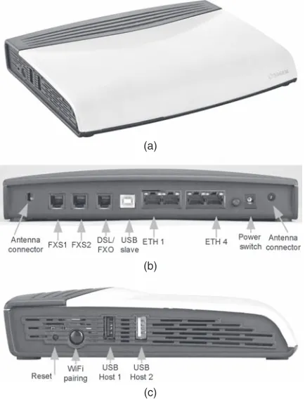
2.4.3 Voice and Fax Software on VoIP Adapter / 31 2.4.4 Residential Gateway / 33
2.4.5 Residential Gateway Example / 35 2.4.6 IP Phones / 35
2.4.7 Wireless LAN-Based IP Phone / 38 2.4.8 VoIP Soft Phones on PC / 38 2.4.9 VoIP-to-PSTN Gateway / 39 2.4.10 IP PBX Adapter / 40
2.4.11 Hosting Long-Distance VoIP through PSTN / 40 2.4.12 Subscribed VoIP Services / 40
2.5 VoIP Signaling / 41
2.5.1 VoIP–H.323 Overview / 41 2.5.2 VoIP–MGCP Overview / 42 2.5.3 SIP Signaling / 42
2.5.4 SIP Call Flow / 43
3 Voice Compression 49
3.1 Compression Codecs / 50 3.2 G.711 Compression / 50
3.2.1 µ-Law Compression of Analog Signal / 51 3.2.2 PCMU for Digitized Signals / 51
3.2.3 PCMU Quantization Effects / 54
3.2.4 A-Law Compression for Analog Signals / 55 3.2.5 PCMA for Digitized Signals / 55
3.2.6 PCMA Quantization Effects / 56
3.2.7 Power Levels in PCMU/PCMA and SNR / 56 3.3 Speech Redundancies and Compression / 60
3.4 G.726 or ADPCM Compression / 60 3.4.1 G.726 Encoder and Decoder / 61 3.5 Wideband Voice / 62
CONTENTS ix
3.6 G.729 Family of Low-Bit-Rate Codecs / 63 3.6.1 G.729 Codec / 65
3.7 Miscellaneous Narrow and Wideband Codecs / 67 3.7.1 Narrowband Codecs / 67
3.7.2 Wideband Codecs / 69 3.8 Codecs and Overload Levels / 70 3.9 Voice Quality of Codecs / 70
3.9.1 Discussion on Wideband codec Voice Quality / 73 3.10 C-Source Code for Codecs / 74
3.11 Codecs in VoIP Deployment / 74
4 Generic VAD/CNG for Waveform codecs 76
4.1 VAD/CNG and Codecs / 77
4.2 Generic VAD/CNG Functionality / 78 4.3 Comfort Noise Payload Format / 78
4.4 G.711 Appendix II VAD/CNG Algorithm / 80 4.4.1 DTX Conditions / 82
4.4.2 CNG Algorithm / 83 4.5 Power-Based VAD/CNG / 83
4.5.1 Signal-Level Mapping Differences / 84 4.6 VAD/CNG in Low-Bit-Rate Codecs / 85 4.7 Miscellaneous Aspects of VAD/CNG / 86
4.7.1 RTP Packetization of VAD/CNG Packets / 86 4.7.2 VAD Duplicate Packets / 87
4.7.3 VAD/CNG Interoperability / 87 4.7.4 Network Bandwidth Saving / 88 4.7.5 VAD/CNG Testing / 88
4.7.6 VAD Clippings / 89 4.8 Summary on VAD/CNG / 89
5 Packet Loss Concealment Techniques 91
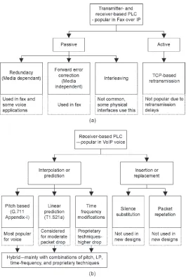
5.1 Packet Loss Concealment Overview / 91 5.2 Packet Loss Concealment Techniques / 92 5.3 Transmitter- and Receiver-Based Techniques / 94
5.3.1 Retransmission or the TCP-Based Method / 94 5.3.2 FEC / 95
5.3.3 Redundancy / 97 5.3.4 Interleaving / 98
5.5 PLC Techniques Description / 101
5.5.1 PLC Based on G.711 Appendix-I / 101 5.5.2 LP-Based PLC / 105
5.5.3 Hybrid Methods / 107 5.6 PLC for Low-Bit-Rate Codecs / 108 5.7 PLC Testing / 110
5.8 PLC Summary and Discussion / 111
6 ECHO Cancellation 113
6.1 Talker and Listener Echo in PSTN Voice Call / 114 6.1.1 Echo and Loudness Ratings / 116
6.2 Naming Conventions in Echo Canceller / 119 6.3 Line and Acoustic Echo Canceller / 120 6.4 Talker Echo Levels and Delay / 123
6.4.1 Relating TELR and G.168 Recommendations / 126 6.4.2 Convergence Time / 126
6.5 Echo Cancellation in VoIP Adapters / 127 6.5.1 Fixed and Nonstationary Delays / 129
6.5.2 Automatic Level Control with Echo Cancellers / 129 6.5.3 Linear and Nonlinear Echo with Example / 130 6.5.4 Linear Echo Improvement with 16-Bit Samples / 130 6.6 Echo Path / 131
6.6.1 Delay Offset and Tail-Free Operations to Reduce Echo Span / 131
6.7 Adaptation Filtering Algorithms / 132
6.7.1 Adaptive Transversal Filter with LMS / 133
6.7.2 Overview on Adaptive Filtering with RLS and Affi ne Projections / 136
6.8 Echo Canceller Control Functions / 137 6.8.1 Double Talk Detection / 139 6.8.2 NonLinear Processing / 141
6.8.3 Monitoring and Confi guration / 144 6.9 Echo Cancellation in Multiple VoIP Terminals / 144
6.9.1 Echo Cancellation in IP and WiFi Handsets / 144 6.9.2 Echo in VoIP–PSTN Gateways / 145
6.9.3 Echo in PC-Based Softphones / 145 6.10 Echo Canceller Testing / 145
6.10.1 Simulated Tests / 147
CONTENTS xi
7 DTMF Detection, Generation, and Rejection 151
7.1 Specifi cations of DTMF Tones / 152 7.2 DTMF Tones Generation / 152
7.2.1 Sine Wave Computation in the Processor / 155 7.2.2 Digital Sinusoidal Oscillator Method / 156 7.3 DTMF Detection / 156
7.4 Goertzel Filtering with Linear Filtering / 158 7.4.1 Selection of Frequency Bins / 159 7.4.2 Goertzel Filtering Example / 160
7.4.3 Goertzel Filtering in the Presence of Frequency Drifted Tones / 161
7.4.4 Frequency Drift Trade-Offs for the Highest DTMF Tone / 163
7.4.5 Frequency Spacing and Processing Duration Trade-Offs / 164
7.4.6 Frequency Twist Infl uences / 165
7.4.7 Overall DTMF Processing with Goertzel Filtering / 165 7.5 Tone Detection Using Teager and Kaiser Energy Operator / 167 7.6 DFT or FFT Processing / 171
7.7 DTMF Rejection / 171
7.8 DTMF RFC2833 Processing / 174
7.8.1 RTP Payload Format for Telephone Digits / 175 7.8.2 RFC2833 Telephone-Event Negotiation / 176 7.9 DTMF Testing / 177
7.10 Summary and Discussions / 178
8 Caller ID Features in VoIP 179
8.1 FSK Caller ID on PSTN / 180
8.2 FSK Caller ID Data Transport Protocol / 183 8.2.1 Physical Layer / 183
8.2.2 Data Link Layer / 184 8.2.3 Presentation Layer / 187 8.2.4 Application Layer / 188 8.3 DTMF-Based Caller ID / 188
8.3.1 DMTF Caller ID on PSTN / 188 8.4 Country-Specifi c Caller ID Overview / 190 8.5 Caller ID in VoIP / 191
8.6 Call Wait Caller ID / 193
8.6.1 Call Wait ID Flow in PSTN / 193 8.6.2 Call Wait ID Signals and Tones / 195 8.6.3 Call Wait ID Functioning in VoIP / 197
8.7 Caller ID on FXO Interfaces / 198 8.7.1 FXO FSK Detections / 200
8.7.2 Caller ID Pass-Through in FXO-to-FXS Call / 201 8.7.3 Caller ID on WiFi and IP Phones / 201
8.8 Summary and Discussions / 202
9 Wideband Voice Modules Operation 203
9.1 Wideband Voice Examples / 204
9.1.1 Wideband VoIP Calls with Computer Softphones / 204 9.1.2 Wideband IP Phones / 204
9.1.3 WiFi Handsets / 205 9.1.4 Wideband Phones / 205 9.1.5 DECT Phones / 206 9.1.6 Bluetooth Phones / 206 9.1.7 Mobile Phones / 206
9.1.8 Wideband Calls with VoIP Adapters / 206 9.2 Wideband VoIP Adapter / 207
9.2.1 Wideband and Narrowband Modules Operation in the Adapter / 208
9.3 Wideband Voice Summary / 214
10 Packetization—RTP, RTCP, and Jitter Buffer 215
10.1 Real-Time Protocol (RTP) / 215 10.2 RTP Control Protocol (RTCP) / 218
10.2.1 RTCP-XR Parameters / 218 10.3 VoIP Packet Impediments / 219
10.3.1 Sources of Packet Impediments and Helpful Actions / 219 10.4 Jitter Buffer / 222
10.5 Adaptive Jitter Buffer / 224
10.5.1 Talk-Spurt-Based Adjustments / 225 10.5.2 Non-Talk-Spurt-Based Adjustments / 226 10.5.3 Voice Flow and Delay Variations Mapping / 227 10.6 Adapting to Delay Variations / 228
10.7 AJB Algorithms Overview / 230
10.7.1 Playout Based on Known Timing Reference and Talk-Spurts / 231
10.7.2 Playout During Spike / 232
10.7.3 Non-Talk-spurt-Based Jitter Calculations / 233 10.7.4 Alternate Way of Estimating Network Delay / 234 10.7.5 Playout Time and Jitter Buffer Size / 235
CONTENTS xiii
10.8 Adaptive Jitter Buffer Implementation Guidelines / 239 10.9 Fixed Jitter Buffer Implementation Guidelines / 241
11 VoIP Voice—Network Bit Rate Calculations 242
11.1 Voice Compression and Bit Rate Overview / 243 11.2 Voice Payload and Headers / 244
11.3 Ethernet, DSL, and Cable Interfaces for VoIP / 245
11.3.1 VoIP Voice Packets on an Ethernet Interface / 246 11.3.2 VoIP Voice Packets on an Ethernet with VLAN / 247 11.4 VoIP Voice Packets on a DSL Interface / 249
11.4.1 VoIP on a DSL Interface with PPPoE / 249 11.5 VoIP Voice Packets on a Cable Interface / 249 11.6 Bit Rate Calculation for Different codecs / 253 11.7 Bit Rate with VAD/CNG / 253
11.8 Bit Rate with RTCP, RTCP-XR, and Signaling / 254 11.9 Summary on VoIP Bit Rate / 254
11.9.1 Packet Size Choice / 256
11.9.2 Delay Increase Example for Large Voice Packets / 256
12 Clock Sources for VoIP Applications 257
12.1 PSTN Systems and Clocks / 259 12.2 VoIP System Clock Options / 259
12.2.1 Using Precision Crystal to Work with Processors / 260 12.2.2 External Clock Generator/Oscillator / 261
12.2.3 Deriving Clock from PSTN / 262 12.2.4 Network Timing Reference (NTR) / 262 12.2.5 NTP for Timing and Clock Generation / 262 12.3 Clock Timing Deviations Relating to VoIP Packets / 263
12.3.1 Interpreting Clock Drifts from Distortion Goal of the Voice Signal / 264
12.4 Measuring Clock PPM / 266
12.4.1 External Estimate from Frequency Transmission Measurements / 266
12.4.2 External Measurements from Packet Hits / 267 12.5 Clock Drift Infl uence on Voice and Fax Calls / 268
13 VoIP Voice Testing 269
13.1 Basic Test Setup / 269
13.3 Analog Front-End Voice Transmission Tests / 274 13.4 Telephone Line Monitor for Tones and Timing
Characteristics / 274
13.5 MOS—PSQM, PAMS, and PESQ Measurements / 275 13.6 Bulk Calls for Stress Testing / 276
13.7 Network Impediments Creation / 277 13.8 VoIP Packets Analysis / 278
13.9 Compliance Tests / 278 13.10 VoIP Interoperability / 278 13.11 Deployment Tests / 279
13.12 Voice Quality Certifi cations / 280
13.13 VoIP Speech Quality Tests by the ETSI / 280 13.14 User Operational Considerations / 281
14 Fax Operation on PSTN, Modulations, and Fax Messages 282
14.1 Fax Machine Overview / 284 14.2 Fax Image Coding Schemes / 286
14.2.1 Modifi ed Huffman 1-D Coding / 287 14.2.2 Modifi ed Read (MR) 2-D Scheme / 288 14.2.3 Modifi ed Modifi ed Read (MMR) Scheme / 289 14.2.4 JPEG Image Coding / 289
14.2.5 JBIG Coding / 290 14.3 Fax Modulation Rates / 290 14.4 PSTN Fax Call Phases / 291
14.4.1 Multiple Pages and Fax Call Phases / 296 14.4.2 Fax Call Timeouts / 297
14.4.3 Fax Call with ECM / 297 14.5 Fax and Modem Tones Basics / 300
14.5.1 CNG Tone / 301
14.5.2 CED (or ANS) Tone / 301 14.5.3 Modem or /ANS Tone / 301 14.5.4 ANSam Tone / 302
14.5.5 /ANSam Tone / 302
14.5.6 V.21 Preamble Sequence / 302 14.5.7 Modems Call Setup Tones / 303 14.6 Tones Detection / 303
14.6.1 CNG Fax Tone Detection / 305
14.6.2 ANS Family Fax and Modem Detections / 305 14.6.3 Detection Steps for /ANS / 307
CONTENTS xv
14.7 Fax Modulations and Demodulations / 309 14.7.1 Modulation / 309
14.7.2 Demodulation / 310 14.8 V.21 Fax Modem / 311
14.8.1 V.21 Implementation Aspects / 311 14.8.2 V.21 Demodulation / 312
14.9 V.27ter Fax Modem / 313 14.9.1 V.27 Modulator / 314 14.9.2 V.27 Demodulator / 317 14.10 V.29 Modem / 318
14.11 V.17 Modem / 321
14.11.1 V.17 Modulator / 323 14.11.2 V.17 Demodulator / 324 14.12 V.34 Fax Modem / 325
14.13 V.21 HDLC Framing and Deframing / 326 14.14 HDLC Messages in ECM / 331
14.15 Summary and Discussions on Fax / 332
15 Fax Over IP and Modem Over IP 333
15.1 Fax over IP Overview / 333 15.2 Fax over IP Benefi ts / 336
15.3 Fax Basic Functionality and Detecting Fax Call / 337 15.4 T.38 Fax Relay / 339
15.4.1 HDLC Messages in PSTN and Fax over IP / 344 15.4.2 T.38 Fax Relay with ECM Support / 345
15.5 Fax Pass-Through / 346
15.5.1 T.38 and Fax Pass-Through Trade-Offs / 348 15.6 Fax over IP Interoperability Challenges / 348
15.6.1 Interoperability with Fax Machines / 349 15.6.2 Deviations in Fax Call Tones / 349
15.6.3 Handling of Voice to T.38 Fax Call Switching / 350 15.6.4 Interoperability with VoIP Adapters at Different
Rates / 350
15.6.5 Interoperability with VoIP Adapters and Gateways / 351 15.6.6 Packet Payload and Format Issues / 352
15.6.7 IP Network Impediments / 354
15.6.8 Miscellaneous Topics on Fax Call Packets and Timing / 354
15.8.1 Modem Simple Connectivity through an FXO / 359 15.8.2 Modem Connectivity through a VoIP Pass-Through / 360 15.8.3 Modem over IP in the VoIP Gateway / 360
15.9 Guidelines for Fax and Modem Pass-Through in VoIP / 362 15.9.1 Views on VoIP Fax and Modem Deployments / 364 15.10 VoIP Fax Tests / 365
15.10.1 Testing with Multiple Fax Machines / 365 15.10.2 Fax Interoperability Tests / 368
15.10.3 Fax Testing with Data Traffi c / 369
15.10.4 End-to-End VoIP Fax Testing with IP Impediments / 369 15.10.5 Diffi culties with Fax Tests / 370
16 Fax Over IP Payload Formats and Bit Rate Calculations 371
16.1 Overview on T.38 and G.711 Pass-Through Bit Rate / 372 16.2 G.711 Fax Pass-Through Bit Rate / 374
16.3 T.38 Basic Payload Bytes for V.27ter, V.29, V.17, and V.34 / 374 16.4 Overview on Redundant and Duplicate Fax Packets / 376 16.5 T.38 IFP Packets / 378
16.5.1 T.30 Indicator Packets / 378 16.5.2 T.30 Data Packets / 380 16.6 IFP over TCP (TCP/IP/IFP) / 381 16.7 IFP over UDP / 382
16.7.1 IFP over RTP / 382
16.7.2 IFP over UDPTL—Primary and Secondary Packets / 385 16.8 T.38 UDPTL-Based Bit Rate Calculation with Redundancy / 387 16.9 Fax UDPTL-Based Bit Rate on Ethernet and DSL Interfaces / 388
16.9.1 Bit Rate Change Among Redundancy and FEC / 391 16.9.2 Bit Rate Change in Silence Zones / 391
16.10 T.38 Bit Rate Recommendations / 392
17 Country Deviations of the PSTN Mapped to VoIP 393
17.1 Country-Specifi c Deviations / 394
17.1.1 Central-Offi ce-Specifi c Deviations Mapped to VoIP / 394 17.1.2 Transmission Lines / 395
17.1.3 Telephone Deviations / 395
17.2 Country-Specifi c Deviations on VoIP Interfaces / 396 17.2.1 Telephone Impedance Programmed on the VoIP
Adapter / 396
17.2.2 Hybrid Matching for Multiple Countries / 397 17.3 Call Progress Tones for Multiple Countries / 399
CONTENTS xvii
17.3.2 Other Call Progress Tones / 400 17.3.3 Basic Tones and Ring—Example / 402 17.3.4 Ringer Equivalent Number (REN) / 403 17.4 Call Progress Tone Detectors / 404
18 Voice Packets Jitter with Large Data Packets 406
18.1 ATM Cells and Transmission / 408
18.2 IPQoS and Queuing Jitter on an Interface / 410
18.2.1 Fragmenting the Packets for Lower Jitter / 410 18.2.2 Fragmenting of 1514-Byte-Packet Example / 412 18.2.3 Voice Packet Fragmentation / 413
18.2.4 Summary on IPQoS and Fragmentation / 413
19 VoIP on Different Processors and Architectures 414
19.1 VoIP on Personal Computers / 415
19.1.1 PC as a Fax Machine and Internet-Aware Fax (IAF) / 416 19.2 VoIP on PC Add-On Cards / 416
19.2.1 PC Add-On Cards for VoIP Instruments / 417 19.3 VoIP on Dedicated Processors / 417
19.4 Operating System Aspects on Different Platforms / 419 19.4.1 Keywords MHz, MCPS, MIPS, and DMIPS
Association / 419
19.4.2 Operating System (OS) Aspects on Computers / 420 19.4.3 Operating System Aspects for DSPs / 421
19.4.4 Operating System Aspects for Network Processors / 421 19.4.5 Operating System Aspects for Network Processor with DSP
Extensions / 421
19.5 Voice Processing Complexity / 422
19.5.1 DSP Arithmetic for Voice Processing / 423
20 VoIP Voice Quality 425
20.1 Voice Quality Measurements / 426
20.1.1 Subjective Measurement Technique / 428 20.1.2 Objective Measurement Techniques / 429 20.1.3 PESQ Measurement / 430
20.1.4 Passive Monitoring Technique / 434 20.2 E-model-Based Voice Quality Estimation / 435
20.2.1 R-Factor Calculations / 437 20.2.2 Bursty Packet Losses / 441
20.3 VoIP Voice Quality Considerations / 446 20.3.1 End-to-End Delay Reduction / 447
20.3.2 Packet Flow Impediments in the VoIP System / 451 20.3.3 AJB with Utilization of Silence Zones / 451
20.3.4 Packet Loss Concealment / 452 20.3.5 Echo Cancellation / 452
20.3.6 Voice Compression Codecs / 453
20.3.7 Transcoding and Conference Operation with Codecs / 454 20.3.8 Codecs and Congestion / 455
20.3.9 Country-Specifi c Deviations / 455 20.3.10 Signal Transmission Characteristics / 455 20.3.11 Transmission Loss Planning / 456
20.3.12 SLIC–CODEC Interface Confi gurations / 456 20.3.13 DTMF Rejection as Annoyance / 456
20.3.14 QoS Considerations / 457
20.3.15 GR-909 Telephone Interface Diagnostics / 457 20.3.16 Miscellaneous Aspects of Voice Quality / 458 20.4 VoIP Voice Quality Summary / 459
20.5 Voice Quality Monitoring and RTCP-XR / 459 20.6 Summary and Discussions / 463
21 VoIP Voice FAQs 464
22 Basic Fax and Fax Over IP FAQs 484
xix
ACKNOWLEDGMENTS
I incorporated points that came from several VoIP and signal processing con-tributing members, as well as from interactions with customers, service pro-viders, third - party developers, interoperability events, publications, standards, recommendations, and conference contributions. I enjoyed the interactions with several contributors from all across the world, and I am grateful for their several decades of contributions, hard work, and foresight in advancing VoIP and signal processing.
I sincerely thank Prof. V. John Mathews, Prof. D. C. Reddy, and Dr. V. V. Krishna for their close technical and personal guidance while going through various stages of compiling this publication.
Several members devoted time in reviewing the material. I thank Dhruva Kumar N and Vasuki MP (Encore Software, India) for reviewing fax chapters and sharing several technical views; Simon Brewer (Analog Devices, Inc.) and his team members for sharing several technical views and knowledge. I would like to thank my colleagues Darren Hutchinson, Chris Moore, Sreenivasulu Kesineni, James Xu, and A.V. Ramana for reviewing some of the chapters.
At Ikanos Communications, Inc., several members provided encourage-ment for this effort. I thank Sam Heidari, Sanjeev Challa, Ravi Selvaraj, Dean Westman, Michael Ricci, Fred Koehler, Sandeep Harpalani, Ravindra Bhilave, Margo Westfall, Noah Mesel, and my software team members.
Special thanks to the following team members: Venkateshwarlu Vangala, Vijay S. Kalakotla, Hemavathi Lakkalapudi, J. Radha Krishna Simha and S.Venkateswara Rao for compiling some of the sections, several deep technical discussions, and technical review of chapters. I would like to recognize the per-sistent efforts of Hemavathi Lakkalapudi that helped me in concluding several chapters in a timely manner, validating several illustrations, and tables, and a lot of editing and review work; my appreciation also goes to J. Radha Krishna Simha for verifying some of the algorithms and formulating the results.
I would like to thank my friends, especially to Sushil Gote, for reviewing several chapters. I also thank several agencies in granting permissions to use their technical material, as well as the John Wiley editorial staff for their friendly support in completing this publication.
S ivannarayana N agireddi
ABOUT THE AUTHOR
Sivannarayana Nagireddi, PhD, is currently working as the architect of voice over IP solutions at Ikanos Communications, Inc., and leads DSP and VoIP team. Dr. Sivannarayana and his team developed VoIP solutions including signal processing algorithms for voice and fax enabled residential gateway processors, which have been deployed by telecommunications providers.
Sivannarayana has been working on digital signal processing and systems for the last 22 years. His contributions in voice and VoIP started in 1999 with Encore Software, India. In early 2000, he built a DSP team for voice applica-tions for Chiplogic India, and later on by mid - 2000, he started managing VoIP solutions for Chiplogic USA. During the merger of Chiplogic with Analog Devices, Inc., he continued his VoIP solutions effort for Analog Devices, Inc. After working for 5 years at Analog Devices, Inc., he moved to Ikanos Com-munications, Inc., at the time of the acquisition of the network processor and ADSL ASIC product lines from Analog Devices, Inc.
Prior to contributions into voice and VoIP applications, for about 13 years from 1986 to 1999, he was working on signal processing algorithms and building systems for communication, radars, image processing, and medical applications.
Sivannarayana graduated with a degree in engineering from the Institute of Electronics and Telecommunications Engineering (IETE), New Delhi, India, in 1985. He received a Masters degree in electronics and communica-tions engineering (ECE) from Osmania University, India. He was then awarded the PhD from the ECE Department, Osmania University, with a focus on wavelet signal processing applications.
His favorite topics are time - frequency analysis and communication signal processing, as well as building complete systems and supporting them for suc-cessful use. He is a member of the IEEE, a Fellow of IETE - India, and a reviewer for Medical Engineering & Physics Journal (Elsevier - UK).
xxiii
PREFACE
Voice over IP (VoIP) gained popularity through actual deployments and by making use of VoIP - based telephone and fax calls with global roaming and connectivity via the Internet. Several decades of effort have gone into VoIP, and these efforts are benefi tting real applications. Several valuable books have been published by experts in the fi eld. While I was building the team, and training them, and conducting several design and support phases, I felt like a consolidated view and material on VoIP voice and fax signal processing was missing. Several contributions in the form of white papers, application notes, data sheets, standards, several books at the system level, and specialized books on signaling, speech compression, echo cancellation, and voice quality exist. Fax processing is available in books mainly for a public switched telephone network (PSTN), several white papers on fax over IP (FoIP), and a lot of ITU recommendations.
In this book, I am trying to bring out a consolidated view and basic approach with interpretation on popularly used techniques mapped to VoIP voice and fax signal processing. As a summary, this book broadly covers topics such as PSTN and VoIP overview, VoIP infrastructure, voice interfaces, voice signal processing modules and practical aspects, wideband voice, packetization, voice bit rate on multiple network interfaces, testing at module level and as a total VoIP system, fax on PSTN, FoIP processing, FoIP anomalies, testing, FoIP bit rates, miscellaneous topics that include country - specifi c deviations, bandwidth issues, voice quality improvements, processors and OS, and FAQs on VoIP and FoIP.
In Chapter 3 , the popular voice compression codecs considered for VoIP deployment and their voice quality considerations one presented. Chapter 4 is on VAD/CNG for saving Internet bandwidth. Various inter - operation issues and testing is also given in this chapter. Chapter 5 is on packet loss conceal-ment that improves voice quality in packet loss conditions. These three chapters are presented in a row to deal with voice compression and its exten-sions. Required overview on software, testing, complexity, quality, and their dependencies are also presented in these three chapters.
Echo cancellation is a big topic with several books exclusively written on that topic. I covered in Chapter 6 concepts mapped to telephones, telephone interfaces, VoIP CPE echo generation, rejection, and testing. DTMF is more of a time - frequency analysis problem with time sensitivity for generation, detection and rejection operations. In Chapter 7 , a consolidated view of DTMF with illustrations and mathematical derivations for tones generation, detec-tion, and rejection is given. Required emphasis on testing and country - specifi c deviations are also given in Chapter 7 . As an extension on DTMF, Chapter 8 presents about different caller ID features that have close relations with basic tones, DTMF, phone and interfaces, various timing formats, caller ID and call progress tones detection, and working principles. Chapter 9 is on wideband voice with an example created using a VoIP adapter that addresses both narrow and wideband combinations. Wideband voice provides higher quality and is expected to be widely available in terminals such as IP phones, WiFi phones, and multimedia terminals.
Chapter 10 is on RTP, RTCP, packetization, packet impediments, and jitter buffers. On jitter buffers, several details are provided with illustrations, math-ematical formulations, algorithms, various modes of operations, and helpful recommendations included. The VoIP bit rates from various codecs, network interfaces, and recommendations from practical deployments are given in Chapter 11 . The network bit rate is usually given up to VoIP headers. In this book, interface headers, exact calculations, and tables with codec, packetiza-tion, and network interfaces are presented. Some clock options and interpreta-tion of clock infl uences with simple calculainterpreta-tions are given in Chapter 12 . VoIP quality is infl uenced by the clock oscillator frequency and its stability. In Chapter 13 , a high - level description of the VoIP voice tests and some of the instruments used for testing are presented.
PREFACE xxv
small fraction of it. In Chapter 16 , detailed headers and bandwidth calculations on Ethernet and DSL interfaces for various fax modulation rates and redun-dancy levels are given.
Similar to PSTN, VoIP has several dependencies for multiple country deployments that are discussed in Chapter 17 . Each country and region has several deviations in its central offi ce confi gurations, such as transmission lines, telephone impedances, tones, and acoustics. Chapter 18 is on IPQoS issues related to the bandlimited network, delay, and jitter for voice packets. Inter-pretation of the bandlimited nature, bandwidth, delay calculations, and recom-mendations for various packet sizes as a trade - off among packet sizes, delays, and fragmentation are given in this Chapter 18 . The goal here is to improve the voice quality. Architectural, hardware processors, processing, and operat-ing system considerations for VoIP are given in Chapter 19 . Chapter 20 dis-cusses consolidation of voice quality evaluation as well as various quality assessments through subjective, PESQ, and E - model. A list of major contribu-tors of quality degradation and improvement options are included in this chapter.
Several questions and answers on voice and VoIP are provided in Chapter 21 . About 100 questions and answers are given that systematically cover the topics listed in this book and are supplemented with several points that could not be directly addressed in continuity. Similarly, a fax FAQ section is given in Chapter 22 . My expectation is that a sequential reading of these fax FAQs will give a quick overview of the fax processing fl ow in PSTN and FoIP.
The algorithms and mathematics are made fairly simple like arithmetic, and they are supplemented with several illustrations, direct results in tables, and summaries or recommendations on various aspects. Several FAQs in Chapters 21 and 22 will help for easy reading of the book. I tried to make this book simple to understand by many readers across several roles. I hope this book will help in understanding voice and fax signal processing for many new engi-neers, new contributors of VoIP, and students at the graduate and postgraduate level, as well as for managers, business, sales, and marketing teams, customers, and service providers.
test functions (in the telephone interface)
GLOSSARY xxix
1
1
VoIP Voice and Fax Signal Processing, by Sivannarayana Nagireddi Copyright © 2008 by John Wiley & Sons, Inc.
PSTN BASIC
INFRASTRUCTURE,
INTERFACES,
AND SIGNALS
1.1 PSTN CO AND DLC
In this section, an overview of central offi ces and DLCs is presented. An analog CO provides services to the user, and in recent times, analog central offi ces were replaced with a combination of digital CO and DLC.
1.1.1 Analog CO
Analog telephony requires a two - wire analog TIP - RING interface. Several years back, the PSTN CO was directly providing several pairs of analog lines to the closest junction box, and from there, individual TIP - RING wire pairs were being distributed to the subscriber [URL (IEC - DLC) ]. When a sub-scriber is far (5000 to 15,000 feet) from the CO, long - distance analog lines can create distortions and signal attenuation. To counter this problem, bigger diameter wires and compensating loading coils were used with analog CO. Sometimes the line voltage is increased at the CO to cater for voltage drop over long lines. For a coverage area of a few miles in diameter, this approach may still be used. Overall, using long lines from the CO is a costly effort, deployment may not scale up, and voice quality degrades. Additionally, fax and modem calls may operate at a lower speed on long analog lines. For a growing customer base, an analog CO may not scale up properly. A VoIP adapter pro-viding telephone service to the end user closely resembles the analog CO by providing telephone interfaces like PSTN DLC or CO and by allowing voice calls through an Internet connection.
1.1.2 Digital CO and DLC
including coaxial cable, digital subscriber line (DSL), or a combination of these that are used for higher end requirements with NGDLC. NGDLC are deployed for multiservices of voice, video and data as well as various Internet services with the right interfaces.
1.2 PSTN USER INTERFACES
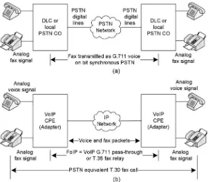
PSTN end users will get services through FXS, ISDN, and the T1/E1 family of interfaces [URL (TIA - 496B) , URL (T1/E1) , URL (ISDN) ]. These interfaces are also used in the migration of VoIP voice and fax solutions. As shown in Fig. 1.1 , the telephone, fax, and dial - up modem are connected on an FXS interface. The FXO interface is part of a telephone, fax, and modem. Some COs provide an ISDN interface for residential applications. The T1/E1 families of interfaces are mainly used with PBX and enterprise services.
1.2.1 FXS and FXO Analog Interfaces
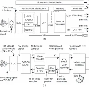
A PSTN wall socket is the FXS interface given to the subscriber for connecting a telephone. FXS is the two - wire TIP - RING interface provided by the PSTN CO or DLC. This interface is used for connecting telephones, fax machines, and dial - up modems. FXS supplies battery voltage, high - voltage ring, and suf-fi cient current to drive three to suf-fi ve parallel phones. A subscriber line interface circuit (SLIC) and a subscriber line access circuit (SLAC) are the main com-ponents of the FXS interface. SLIC consists of a two - to - four - wire hybrid and of high - voltage electronics. SLAC is the interface between a SLIC analog signal and processor digital interface.
The FXO receives battery voltages from the PSTN FXS interface. Some-times the FXO interface is known as a passive interface, which means the FXO will not generate a high - voltage battery on analog TIP - RING interfaces. The FXO interface is available on the TIP - RING connections from a phone, fax machine, or modem. Subscribers can connect this FXO interface to the FXS
Figure 1.1. PSTN digital offi ce and interfaces.
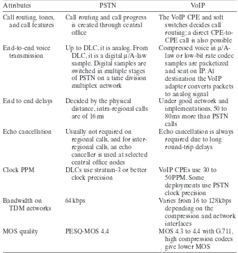
interface provided by the central offi ce, PBX, or VoIP adapter. PBX systems will use FXS on one side to connect to multiple phones and may use multiple FXO interfaces to connect to PSTN CO or DLC. The other popular name used for this FXO interface is the digital access arrangement (DAA). The DAA name is mainly associated with dial - up modems. In simplest form, multiple FXOs can be connected on one FXS interface. FXS is the main active battery source to supply current to multiple FXO interfaces. FXS and FXO are simple interfaces. Some of the functional differences of FXS and FXO are listed in the Table 1.1 .
1.2.2 SLAC , CODEC and codec – Clarifi cations on Naming Conventions
As explained in Section 1.2.1 , telephone interfaces use SLIC and SLAC. SLIC converts a signal from two - wire TIP - RING interface to a four - wire interface and gives it to SLAC for sampling. Currently, the name hardware CODEC is more popular than SLAC. SLAC/CODEC has several functions as explained in Chapter 17 . CODEC in a simple confi guration consists of a COder [hard-ware with an analog - to - digit converter (ADC)], and DECoder [hard[hard-ware with digital - to - analog converter (DAC)] that samples the analog signal at 8 - or 16 - kHz. FXO interfaces use DAA that also makes use of ADC and DAC for sampling. The name SLIC - SLAC use UPPER - case alphabets. The usage of SLAC equivalent part “ CODEC ” with SLIC - SLAC and SLIC - CODEC is
Passive, can receive voltages
The name “ codec ” with lower - case alphabets is popular for compression. The codec has “ encoder for compression ” and “ decoder for decompression ” of digital samples. The names voice codec, speech codec, compression codec, and low - bit - rate codec or simply with lower case “ codec ” denotes samples compression through computation. Through out this book, the same naming conventions are used.
No hard rules exist for this naming convention. In the literature, lower case name “ codec ” or “ Codec ” is also considered for hardware sampling operations, whereas upper - case “ CODEC ” name is not used to represent compression. Refer the context – sampling hardware (CODEC) or samples compression (codec) for correct interpretation.
1.2.3 TIP - RING , Off - Hook, On - Hook, and POTS Clarifi cations
The terms TIP, RING, off - hook, and on - hook are used frequently in PSTN and VoIP services. A summary of these keywords is given here. TIP and RING are the pair of wires used for telephone connection. These names originated in ref-erence to the phone plug used to make connections in manual switchboards. In manual switchboards, one side of the line makes contact with the TIP of the plug and the other with the RING contact immediately behind the TIP of the plug [URL (POTS) ]. Sleeve is usually of a common point or ground, and this is not used in the current two - wire TIP - RING - based system. Currently, all the tele-phone exchanges are electronic with digital switching. Even in operator - assisted PBX systems, an operator is using telephone keys or soft keys for making the connection. Normal telephones are not now using TIP, RING, or sleeve connec-tors. Some instruments for telephone measurements [URL (Sage935) ] are using TIP - RING sleeve connectors. The names “ TIP, RING ” continued for the two wires used for connecting telephones and central offi ces. A picture to represent this TIP - RING connector is available at reference [URL (POTS) ].
The terms “ off - hook ” and “ on - hook ” were used in the early days of tele-phone usage. They refer to the handset position with respect to the cradle of the telephone. In the early telephones, the phone handset was lifted from the hook and was called off - hook. Keeping the back of phone on the hook was called on - hook. On - hook disconnects the phone connection. Off - hook is for getting the dial tone or for continuing the voice call. This hook switch can be clearly seen on most public phones mounted vertically. On public phones, the handset is physically hanging on the hook switch. Lifting the handset from the hook switch is off the hook, and putting the handset back on the hook is the on the hook. A hook switch is also available in handset - based modern phones. The hook may be a little button that pops up on lifting the handset and goes down when putting back the handset.
and so on, have remained same. Hence, the current analog phones are also referred as POTS phones. The names “ analog phone ” , “ normal phone ” , “ house phone ” , “ POTS phone ” , “ two - wire phone ” , or simply “ phone ” are used inter-changeably. In this book, the names “ ring ” or “ Ring ” are used for phone ringing alert, and name “ RING ” is used for telephone physical interface wire.
1.2.4 ISDN Interface
ISDN [URL (ISDN) ] gives the highest possible PSTN quality than analog telephony. ISDN is used as a reference for comparing voice call quality of narrowband (300 to 3400 Hz) voice. It is also used for high - quality voice and fax at the highest speed of 33,600 bits per second (bps) and for dial - up modem at higher data rates of 56 kilo bits per second (kbps) from one of the two bearer (B) - channels. ISDN is a four - wire interface with a separate send and receive pair of wires. The physical interface of ISDN is of analog, but the transmission content is a bit stream of information. This interface in a system allows simul-taneous voice conversations and data communication. With ISDN, voice and data are carried by two B - channels occupying a bandwidth of 64 kbps per channel. Some PSTN switches may limit B - channels to 56 kbps. A data (D) channel handles signaling and data at 16 kbps. There are two types of ISDN services: basic rate interface (BRI) and primary rate interface (PRI). BRI consists of 2B + D, two 64 kbps B - channels and one 16 kbps D - channel for a total of 144 kbps. The basic service is intended to meet the needs of individual users. For enterprise use, PRI is used, and this goes by the name H - series with a suffi x based on the channel density. H - channels provide a way to aggregate several B - channels. They are classifi ed as H 0 = 384 kbps (six B - channels),
H 10 = 1472 kbps (23 B - channels), H 11 = 1536 kbps (24 B - channels), and H 12 =
1920 kbps (30 useful B - channels). H 12 is also known as international E1.
1.2.5 T 1/ E 1 Family Digital Interface
T1/E1 is a four - wire interface [URL (T1/E1) ]. It uses two wires for send and two wires for receive. T1 is used in North America, and E1 is used in Europe with a T1 equivalent interface named J1 used in Japan. In most of the systems, the same infrastructure and interfaces will work for both T1 and E1 without changing hardware electronics. These interfaces are used for enterprise solu-tions for voice and data communicasolu-tions. The physical connector interface will look similar to the Ethernet interface. Sometimes two coaxial cables are also used for this interface. PSTN DLC/NGDLC or CO will be supplying this interface to the user. Offi ces also use the T1/E1 interface for Internet service. In general, T1/E1 is used for voice, data, or a combination of voice and data.
The resulting data stream is of 24 × 8 × 8 kHz = 1536 kbps making each frame data 192 bits (1536 kbps/8000). In T1, one - bit synchronization is used for every frame at 8 kHz making each frame data 193 bits and total bit rate 1.544 Mbps. Of 24 channels of T1, one channel is usually allocated for telephone signaling. This process is represented as 23B + D channels, meaning one D - channel is used for data or signaling. In E1, 32 digitized channels are multiplexed into a single digital data stream, resulting in 32 × 8 bits × 8 kHz = 2048 kbps. The resulting TDM frame size is 256 bits and frames are at 8 kHz.
1.3 DATA SERVICES ON TELEPHONE LINES
Telephone, fax, and modem use voice band frequencies (300 to 3400 Hz) on the telephone wires. Fax and modem are data terminals. Fax is an independent device that sends data modulated into voice band. A dial - up modem also modulates data into voice band. A dial - up modem is used for Internet con-nectivity and data transfer. Dial - up modems provide data concon-nectivity up to 56 kbps. Some more details on dial - up modems are given in Chapter 15 . Tele-phones, fax machines, and dial - up modems use telephone lines one at a time, but they can work simultaneously with a broadband service like xDSL.
For VoIP, Internet connectivity is essential. A dial - up modem is one of the basic and most popular options for Internet connectivity. It can provide data connectivity of up to 56 kbps, which is suffi cient only with a higher compression VoIP voice call. DSL can provide much higher bandwidth compared with the dial - up modems, and hence, it is used in several deployments for Internet con-nectivity. In theory, both dial - up and DSL can be used together, but when DSL service is used, a dial - up modem may not be required.
1.3.1 DSL Basics
DSL service is provided through the existing analog telephone two - wire inter-face or on four - wire ISDN lines. Voice, fax, and modem signals occupy a 0 - to 4 - kHz band. Telephone wires are capable of carrying wider bandwidth signals to a distance of several thousand feet. DSL technology is based on discrete multi - tone (DMT) modulation using orthogonal frequency division multiplex-ing (OFDM). It operates on an array of N relatively lower rate transceivers in parallel to achieve an overall high rate on a single line. These N information streams are kept separated from one another by sending them on N different subcarriers called sub - bands or subchannels. Thus, DMT is a very fl exible modulation scheme in which each subchannel can carry a different number of bits depending on the channel conditions. The subchannel that supports a higher signal - to - noise ratio (SNR) is loaded with a larger number of bits [Goralski (1998) ].
The asymmetric digital subscriber line (ADSL) given in recommendation ITU - T - G.992.1 (1999) specifi es DMT modulation with a total of 256 subchan-nels centered at frequencies (m)(f s ), where m is a subchannel from 0 to 255
and f s is 4312.5 Hz. Thus, it occupies a bandwidth of (256) (4312.5) = 1.104 MHz
on the telephone line. Not all of these subchannels can be used in practice, as voice band splitting fi lters need to be employed to separate the DSL band from that of the voice band. The recommendation specifi ed for either fre-quency separation of the downstream and upstream channels or separation by echo cancellation. The maximum number of bits allowed on each subchannel is 15, thereby limiting the theoretical maximum downstream rate that can be achieved to (15 bits per subchannel) (255 subchannels) (4000 symbol rate) = 15.3 Mbps. The G.992.1 recommendation specifi es the downstream rate of 8 Mbps and the upstream rate of 1 Mbps.
The asymmetric DSL2 plus (ADSL2+) family [ITU - T - G.992.3 (2005) , G.992.5 (2005) ] occupies analog signal bandwidth from 25 kHz to 2.2 MHz to support downstream data rates up to 24 Mbps. Very high - speed DSL (VDSL) [ITU - T - G.993.1 (2004) , G.993.2 (2006) ] will occupy analog bandwidth up to 17 MHz and some versions up to 30 MHz to support data rates of 50 to 100 Mbps and more. In summary, voice services are continued at low frequency while using the same telephone line for various fl avors of DSL service.
The DSL access multiplexer (DSLAM) is the CO for DSL services. DSL services do not need a high - voltage battery for operation. Hence, isolation in combining and splitting is essential between high voltage for normal telephone operation and low voltage for wideband DSL signals. DSL has to be combined on analog signal lines only. Different combining techniques are used to provide DSL service. Some popular techniques of combining DSL are direct analog combining, remote DSLAM line based, ADSL lines cards, and remote access multiplex (RAM) [URL (IEC - ADSL) ]. Overview on DSL combining methods are given below. It is expected that these techniques and technologies will keep growing and changing with time.
Direct Analog Combining. This technique is applicable for the analog COs that distribute direct analog lines. DSL signals are directly combined on the analog lines with isolation splitter - combiners. This type of operation is possible if the coverage distance is less and the bandwidth requirements are of a few Mbps. Most central offi ces extend services through DLCs; hence, this type of DSL support is not popular.
Remote DSLAM - Based Combining. In this scheme, a complete DSLAM is colocated along with DLCs or is positioned close to the DLC based on the available installation options. DSLAMs are usually maintained in a controlled environment and are managed remotely. The service can be used with any PSTN lines and several fl avors of DSL. The main disadvantage of this method is the cost involved to deploy and maintain. It will also require long wiring if DLC and DSLAM are not located in the same racks.
DLC box slots be reserved for the DSL line cards. Keeping the DSL cards in DLC may minimize the wiring requirements. Management of DSL and DSLAM line cards will be under the same framework. Many deployments use this approach. DSL fl avors keep changing with time. Upgrading the line cards in the fi eld is a major concern of this deployment, and multiple user cards may go through different interoperability issues.
RAM . RAM performs similar functions of providing DSL service. RAM integrates closely with the DLCs. It is a separate small box. The RAM boxes are also called pizza boxes based on their shape. Pizza boxes are stacked and positioned along with the DLCs. RAM - based boxes have the advantage of both remote DSLAM and ADSL line card solutions. These boxes are easy to upgrade, change with another version of box, and scale in density.
1.4 POWER LEVELS AND DIGITAL QUANTIZATION FOR
G.711 m /A - LAW
Telephone line electrical signal power levels are presented in dBm units. Power level expressed in dBm is the power in decibel (dB) with reference to one milliwatt (mW). Power 0 dBm represents one milliwatt of power. One mW is a strong speech level for listening. Usual telephone conversion levels are close to − 16 dBm (25 µ W; µ W is microwatt). ITU - T - G.711 and ITU - T - G.168 (2004) recommendations listed speech power levels and corresponding digital quan-tization mapping for 8 - bit A - law and µ - law. A - law and µ - law (pronounced as Mu) are logarithmic compression methods explained in Chapter 3 under G.711 compression. Telephone interfaces have SLIC and SLAC for converting TIP RING signals to digital samples. SLIC converts a signal from two wire TIP RING interface to a four - wire interface to SLAC. In recent literature, the hardware CODEC name is used instead of SLAC. CODEC consists of a COder, DECoder hardware with an analog - to - digital converter (ADC) and a digital - to - analog converter (DAC) that samples the signals at 8 or 16 kHz. Sampled signals are given to the processor for additional processing. In this chapter, signal levels and the mapping to 16 - bit numbers in A - law and µ - law, are given with reference to dB and dBm scale.
1.4.1 µ - Law Power Levels and Quantization
The maximum µ (read as Mu) - law undistorted power level for the sine wave is 3.17 dBm. Power of 3.17 dBm is 2.0749 mW in 600 Ohms ( Ω ) of telephone impedance. Impedance of 600 Ω is applicable to North America and a few other countries like Japan and Korea. A sine wave of 2.0749 mW in 600 Ω develops 1578 milliVolts (mV) peak or a 3.156 Volts peak - to - peak sine wave amplitude. Voltage of 1578 mV has to be quantized as 8159 amplitude [ITU
T - G.711 (1988) , ITU - T - G.168 (2004) ] in 16 - bit binary numbering format. Assuming linear mapping for calculation purposes, the quantization level is 1578 mV/8159 = 0.1934 mV. Once voice samples are available as per the above quantization of one level per 0.1934 mV, the following formula given in ITU T - G.168 is used for estimating the voice power over a block of samples:
S k n ei
In general, N will be used in signal processing literature for representing blocks of samples and n will be used for an index within the block of samples. In the above equation, to maintain consistency with the ITU recommendations, n is used for denoting block size and i is used for the index.
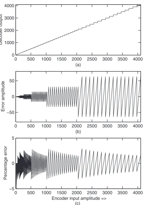
S k n ei power representation in Eq. (1.1) . For a sine wave of peak 4096, this calcula-tion results in 3.14 dBm with out any dependency on frequency. A - law starts distortion to sine wave if it exceeds 3.14 dBm. An amplitude of 4096 for the square wave results in 6.14 dBm. As an example, substituting one com-plete cycle of a 2 - kHz sine wave at 4096 amplitude (four samples for one complete cycle are 0, 4096, 0, − 4096) in A - law power calculation gives 3.14 + 0 dBm = 3.14 dBm. Substituting four constant values of 4096 in A - law power calculation will give 3.14 + 3.0 dBm = 6.14 dBm. A - law supports SNR up to 37 to 41 dB (this varies with signal power level) for the useful speech signal levels.
1.5 SIGNIFICANCE OF POWER LEVELS ON LISTENING
Table 1.2 is given for different power levels starting from +3.17 dBm and down to − 66 dBm in a few suitable steps. In relation to Table 1.2 , summary points are given here [ITU - Handbook (1992) ]. These levels are mainly mapped to the telephone interfaces and voice chain processing built for VoIP. In VoIP, power levels play a role in operation of some voice processing operations such as voice activity detection (VAD)/comfort noise generation (CNG), automatic gain control (AGC), echo level, and ideal channel noise. PSTN systems do not have any power - sensitive module operations such as VAD/CNG. In voltage scale, a 0.775 - Volt RMS sine wave is the same as 0 dBm, terminated in 600 - Ω impedance. The usual speech conversation level is − 16 dBm in power. Some members may speak at a low amplitude below − 24 dBm, which can also happen because of positioning of acoustic interfaces during con-versation. This problem demands more effort by the listener. Automatic gain control (AGC), if employed, starts working from this power level. As per the ITU - T - G.169 (1999) recommendation, a maximum gain of 15 dB is used on low - level speech signals. A peak - to - average (PAR) level of speech is 15 to 18 dB [ITU - Handbook (1992) ] for 0.1% of the active speech time. An average speech level of − 12 dBm with 15 dB peak to average can preserve the speech as undistorted.
Table 1.2. Summary on Useful Power Levels and Corresponding A - and µ - Law
dBov, and the suffi x ov stands for overload. It is not related to units of voltage, and it is related to 6.17 dBm = 0 dBov in µ - law compression. More details on these aspects are given in Chapter 4 .
listed in Table 1.2 . An echo power level of even − 60 dBm is considered disturb-ing in VoIP and inter - regional PSTN calls. When no voice is speakdisturb-ing into the telephone or the phone is in mute, some noise overrides in the telephone system because of front - end coupling and power supplies. This noise is called ideal channel noise. These noise levels are maintained to below − 68 dBm and preferably to − 80 dBm. Noise power is expressed in picoWatts (1 picoWatt = 10 − 12 Watt) on a dB scale as dBrnC; suffi x “ C ” denotes the C - message fi lter. A
noise level of 90 dBrn is equivalent to 1 mW or 0 dBm [Bellamy (1991) ].
1.6 TR - 57, IEEE - 743, AND TIA STANDARDS OVERVIEW
In PSTN, communication from the originating CO or DLC to the destination DLC is synchronous digital communication. This process has been well estab-lished over the last several decades. PSTN transmission follows some common standards such as ITU and IEEE and country - specifi c standards like TR - 57 and TIA standards [TR NWT 000057 (1993) , TIA/EIA 470C (2003) , IEEE STD - 743 (1995) ]. PSTN manufacturers use TR - 57 in North America to specify the signaling and transmission requirements for DLC. The FXS interface on VoIP adapters works similar to DLC or analog CO providing the TIP - RING interface. Assuming other favorable conditions for VoIP voice quality, as explained in Chapter 20 , ensuring TR - 57 transmission characteristics helps in improving voice quality. TR - 57 is used in North America, and the current standard is GR - 57 [GR - 57 - CORE (2001) ]. Several other standards are fol-lowed in different countries. For example, Japan makes use of the NTT PSTN specifi cation [URL (NTT - E) ], and France uses the France Telecom STI series [FT ITS - 1 (2007) ] of specifi cations. Most of these country specifi cations are closely related to each other with only a few deviations like end - to - end losses, transmission fi lter characteristics, impedance, and so on. TR - 57 transmission specifi cations can also be followed in achieving voice quality in VoIP systems. In VoIP, some signaling events as call progress tones used in establishing end - to - end calls may go through longer delays than PSTN specifi cation. These deviations will tend to develop during the call establishment phase. Meeting transmission characteristics [TIA/EIA - 912 (2002) ] can take care of established VoIP call voice quality.
1.6.1 TR - 57 Transmission Tests
TR - 57 or GR - 57 transmission summary points and high - level interpretation are given in this section. [Courtesy: Text and parameter values with TR - 57 reference are from “ TR - NWT - 000057 (1993) , Functional criteria for digital loop carrier systems — Chapter 6 ” ; used with the permission from Telcordia, NJ, www.telcordia.com ]. It is suggested to refer to TR - 57 [TR - NWT - 000057 (1993) ] or the recent document GR - 57 [GR - 57 - CORE (2001) ] for the com-plete requirements and detailed specifi cations referred to in this book. Inte-grating these test specifi cations into PSTN and VoIP helps in maintaining the
quality of voice and fax calls. Refer to instrument manuals [URL (Sage options) ] for details on measurements and interpretation.
Return Loss. Return loss happens because of an impedance mismatch of the terminations and the source. It is expressed as the ratio of the outgoing signal to the refl ected signal. It is given as echo return loss (ERL) and singing return loss (SRL) with SRL at both high (Hi) and low (Lo) frequencies. ERL is the frequency - weighted average of the return losses over the 3 - dB bandwidth points of 560 to 1965 Hz. Higher ERL is advantageous and gives lower echo. ERL in dB has to be greater than 18 dB, and this level avoids echo issues in the intraregional calls. In numerical terms, 18 - dB ERL means 1/64th of the power or 1/8th of the voltage returning as echo. It is possible to achieve ERL up to the extent of 24 dB in practical systems with short - loop applications with VoIP gateways. To clarify on a relative scale, an ERL of 24 dB is better than an ERL of 18 dB by 6 dB. SRL is created by a resonance effect at selected frequencies. At some frequencies, the round trip of the echo is created with multiples of 360 ° of phase shift, which makes oscillations sustain for a longer duration. This phenomenon is called “ line is on singing. ” SRL - Lo is the singing return loss for 3 - dB bandwidth low frequencies in the range of 260 to 500 Hz. SRL - Hi is for the high - frequency singing return loss measured in the band of 2200 to 3400 Hz. Details on the band - pass characteristics are given in IEEE STD - 743 [ (1995) , URL (Midcom) ]. The SRL has to be greater than 10 dB. In general, SRL - Hi will be higher than SRL - Lo. Lower dB values of SRL - Hi, SRL - Lo creates annoyance to both talker and listener of the voice call.
Longitudinal Balance. Balance is the match between TIP and RING lines. It provides the discrimination for the common mode signal on the TIP and RING interface or indicates how well the TIP - RING is matching. It is evalu-ated as the ratio of longitudinal to metallic balance. Longitudinal is a common mode signal, and metallic is a differential signal. In the measurements, a common or ground point is required in addition to TIP - RING lines, as given in reference [URL (Sage - Balance) ]. The preferred balance is greater than 65 dB at 1 kHz, but the acceptable balance is 63 dB. In good implementations, a balance of 68 dB is achieved.
Total Loss. It identifi es that the transmitter and receiver are having a required loss. The end - to - end losses have to be within the acceptable limits, including the network cables loss. PSTN systems achieve their highest end to end loss of 8 dB in off - hook, and these losses vary with country - specifi c require-ments. These losses also infl uence the loudness rating (given in Chapters 17 and 20 ) that has a close relationship with voice quality.
TR-57, IEEE-743, AND TIA STANDARDS OVERVIEW 15
response is checked at 0 dBm, and the fl atness goals are of ± 0.5 dB. The refer-ence for comparison of fl atness is at 1004 Hz. With referrefer-ence to a 1004 - Hz frequency response, deviations from 400 to 2800 Hz have to be within ± 0.5 dB as optional and − 0.5 to +1.0 as required. In actual practice, the frequency response is taken from 100 Hz to 3900 Hz in suitable frequency steps. The values between 400 and 2800 Hz are used for comparing the frequency response.
60 - Hz Signal Loss. Signal loss at 60 Hz is not desirable in speech transmis-sion, but this “ mains hum ” can unfortunately be introduced from the AC mains power supply (110 V, 60 Hz). This test is to ensure that a 60 - Hz contribution is at least 20 dB lower than a frequency response at 1004 Hz. This 60 - Hz contribu-tion has to be treated before sampling. If end - to - end loss at 1004 Hz is “ X ” dB, loss at 60 Hz has to be greater than X + 20 dB. In some countries, especially in Europe, 50 Hz is used for power transmission, and therefore, the measure-ments have to be conducted at 50 Hz in those countries even though it is not stated.
Off - Hook Amplitude Tracking. It ensures transmission gain fl atness for dif-ferent amplitudes at 1004 Hz, which is similar to amplitude linearity at the selected frequency. Three different ranges are defi ned in TR - 57. At lower signal levels, A - law and µ - law create more quantization noise, which makes gain deviation to increase below the − 37 - dBm input level. For inputs of greater than or equal to − 37 dBm, maximum deviation is ± 0.5 dB (average of ± 0.25 dB). For inputs of − 37 to − 50 dBm, maximum deviation is ± 1.0 dB. For inputs of − 50 to − 55 dBm, maximum deviation is ± 3.0 dB, which implies that AGC cannot improve linearity for small signals. Most instruments can measure up to a minimum of − 60 dBm. Test instruments use a C - message band - pass fi lter [URL (Sage935) ] for the voice band. In some countries, psophometric (p) - message fi lters are used. The differences are outlined in the ideal channel noise section.
Off - Hook Ideal Channel Noise. In its simplest form, ideal channel noise is the noise heard when microphones are in mute. The noise can be heard in a silent room. Instruments in North America use a C - message fi lter for voice band and measure the noise power in dBrnc. Power in dBrnc (also referred as dBrnC) is C - message weighted noise power with a reference unit of 1 pw. The popular notation is dBrnc for noise power. For voice power, dBm units are used. In simple mapping, 90 dBrn = 0 dBm (1 mw), and with C - message weighting, the mapping is 88 dBrnc = 0 dBm. The psophometric weighting is used in Europe as 87.5 dBp = 0 dBm. The symbol “ dBp ” is used for dBrn with psophometric weighting. The variation is by 2 to 2.5 dB with the weighting windows. The ideal channel noise power has to be better than 18 dBrnc, which is equivalent to 18 − 88 = − 70 dBm. An accepted noise power level is 20 dBrnc = − 68 dBm. Long - distance analog telephony was accepting higher ideal channel noise [Bellamy (1991) ]. After conversion to digital telephony with short analog loops and DLCs, ideal channel noise achieved better levels, as stated in this section.
SNR or Distortion Ratio. The SNR and distortion measure identifi es the SNR limits at the signal level. Lower signal power levels and their SNR results are also important in transmission. A - law or µ - law compression is used in PSTN and VoIP. Both the highest and the lowest signal are coded in 4 bits with 3 - bit level scaling and in 1 bit for sign (polarity of the signal), which limits the possible SNR to 38 – 41 dB with self - quantization effects. With low amplitudes, SNR starts degrading. It is measured with an input sine wave of 1004 to 1020 Hz, and signal power is varied from 0 to − 45 dBm. For input of 0 to − 30 dBm, the required SNR is more than 33 dB (usually > 37 dB is achieved in most systems). For input of − 30 to − 40 dBm, SNR is > 27 dB. For − 40 to − 45 dBm, SNR is > 22 dB. When end - to - end losses are more, or ideal channel noise is not meeting the specifi cations, SNR will be lower for the same input signal levels. The signal - to - total - distortion (STD) ratio that takes into account total distor-tion, including second and third harmonics.
Impulse Noise. Impulse noise is the short duration noise power that exceeds the set thresholds. Impulse noise can create audible tick sounds, and fax/ modems may fall back to a lower bit rate. Ideal channel noise is the steady low - level noise. Impulse noise durations are comparable with 10 - ms duration. Signal loss from phase or amplitude distortion can be noticed during VoIP packet loss, coupling from adjacent channels, ringing, line reversals clock drifts, and a change in power supply load conditions in the hardware. Noise on the interfaces may occupy wider bandwidth. Impulse noise is heard with a C - message fi lter, which means it is limited to the voice band.
TR-57, IEEE-743, AND TIA STANDARDS OVERVIEW 17
47 dBrnc (equivalent to − 41 dBm). In the tone case, with the tone at 1004 Hz, − 13 dBm is sent and impulse noise is measured with a threshold of 65 dBrnc (equal to − 23 dBm). Several conditions with impulse noise exist as given in TR - 57 [TR - NWT - 000057 (1993) ]. The impulse noise counts are also referred to as hits.
Intermodulation Distortion. This test makes use of four tones as per IEEE STD - 743 (1995) with a total input level of − 13 dBm. This test is mainly used for measuring the undesired nonlinearity. A pair of tones around 860 Hz and another pair of tones around 1380 Hz are used in this test. In this test, total second and third harmonic distortions are measured. The second harmonic has to be better than 43 dB, and the third harmonic has to be better than 44 dB.
Single - Frequency Distortion. It measures the distortions to the single pure tone. This distortion is separated into two frequency bands of 0 – 4 kHz and 0 – 12 kHz. In narrowband, the 1004 – 1020 Hz tone at 0 dBm is sent and the observed tones outside the sent tone have to be lower than − 40 dBm in the frequency band of 0 – 4 kHz. In the wideband range, for any input at 0 dBm in the frequency range of 0 – 12 kHz, the observed output at any other frequency outside the sent tone frequency has to be less than − 28 dBm in the 0 – 12 - kHz frequency range. This type of test will require spectrum analyzers.
System Generated Tones. It measures any undesired system generated tones. Send and receive can be in either the terminated mode or the not ter-minated mode with proper impedance. Tones measured at any end have to be less than − 50 dBm in the frequency range of 0 – 16 kHz.
PAR . PAR provides amplitude and phase distortion over time because of transmission impairments [URL (Sage - PAR) ]. A PAR waveform is a complex signal consisting of about 16 non - harmonically related tones with a spectrum that approximates the modem signals in the voice frequency band. In general, PAR takes care of attenuation distortion, envelope distortion, four - tone modu-lation distortion, and phase distortion. PAR is measured on both ends. Most systems achieve a PAR of 94, and an acceptable PAR is 90. The PAR measure-ment cannot reveal what caused this distortion. In many types of equipmeasure-ment, PAR test is replaced with the better 23 - tone test as per IEEE STD - 743 (1995) .